EP1293928A2 - Coordinate input device having non-flat operation surface and electronic apparatus - Google Patents
Coordinate input device having non-flat operation surface and electronic apparatus Download PDFInfo
- Publication number
- EP1293928A2 EP1293928A2 EP02020485A EP02020485A EP1293928A2 EP 1293928 A2 EP1293928 A2 EP 1293928A2 EP 02020485 A EP02020485 A EP 02020485A EP 02020485 A EP02020485 A EP 02020485A EP 1293928 A2 EP1293928 A2 EP 1293928A2
- Authority
- EP
- European Patent Office
- Prior art keywords
- coordinate input
- input device
- operation surface
- shape
- operating member
- Prior art date
- Legal status (The legal status is an assumption and is not a legal conclusion. Google has not performed a legal analysis and makes no representation as to the accuracy of the status listed.)
- Withdrawn
Links
Images


Classifications
-
- G—PHYSICS
- G06—COMPUTING; CALCULATING OR COUNTING
- G06F—ELECTRIC DIGITAL DATA PROCESSING
- G06F3/00—Input arrangements for transferring data to be processed into a form capable of being handled by the computer; Output arrangements for transferring data from processing unit to output unit, e.g. interface arrangements
- G06F3/01—Input arrangements or combined input and output arrangements for interaction between user and computer
- G06F3/03—Arrangements for converting the position or the displacement of a member into a coded form
- G06F3/033—Pointing devices displaced or positioned by the user, e.g. mice, trackballs, pens or joysticks; Accessories therefor
- G06F3/0338—Pointing devices displaced or positioned by the user, e.g. mice, trackballs, pens or joysticks; Accessories therefor with detection of limited linear or angular displacement of an operating part of the device from a neutral position, e.g. isotonic or isometric joysticks
-
- G—PHYSICS
- G06—COMPUTING; CALCULATING OR COUNTING
- G06F—ELECTRIC DIGITAL DATA PROCESSING
- G06F3/00—Input arrangements for transferring data to be processed into a form capable of being handled by the computer; Output arrangements for transferring data from processing unit to output unit, e.g. interface arrangements
- G06F3/01—Input arrangements or combined input and output arrangements for interaction between user and computer
- G06F3/03—Arrangements for converting the position or the displacement of a member into a coded form
- G06F3/041—Digitisers, e.g. for touch screens or touch pads, characterised by the transducing means
- G06F3/044—Digitisers, e.g. for touch screens or touch pads, characterised by the transducing means by capacitive means
- G06F3/0445—Digitisers, e.g. for touch screens or touch pads, characterised by the transducing means by capacitive means using two or more layers of sensing electrodes, e.g. using two layers of electrodes separated by a dielectric layer
-
- G—PHYSICS
- G06—COMPUTING; CALCULATING OR COUNTING
- G06F—ELECTRIC DIGITAL DATA PROCESSING
- G06F3/00—Input arrangements for transferring data to be processed into a form capable of being handled by the computer; Output arrangements for transferring data from processing unit to output unit, e.g. interface arrangements
- G06F3/01—Input arrangements or combined input and output arrangements for interaction between user and computer
- G06F3/03—Arrangements for converting the position or the displacement of a member into a coded form
- G06F3/041—Digitisers, e.g. for touch screens or touch pads, characterised by the transducing means
- G06F3/044—Digitisers, e.g. for touch screens or touch pads, characterised by the transducing means by capacitive means
- G06F3/0446—Digitisers, e.g. for touch screens or touch pads, characterised by the transducing means by capacitive means using a grid-like structure of electrodes in at least two directions, e.g. using row and column electrodes
Definitions
- the present invention relates to coordinate input devices used in computers or game devices for moving a cursor or a character, selecting a function, etc., on a display, and also relates to electronic apparatuses including the coordinate input devices.
- Fig. 14 is a perspective view of a notebook personal computer having a coordinate input device called a touch pad in front of a keyboard.
- This computer 200 includes a main body 201 and a display 203 which is connected to the main body 201 by a hinge at the rear end of the main body 201.
- a keyboard 204, a touch pad (coordinate input device) 205, and operation buttons 206 are provided on the top surface of the main body 201.
- the touch pad 205 has a flat, rectangular shape and is disposed in front of the keyboard 204, and the operation buttons 206 are disposed in front of the touch pad 205.
- the touch pad 205 is constructed such that a cursor, etc., shown on the display 203 can be operated by sliding an operating member, for example, a finger, on the touch pad 205.
- a coordinate input operation for example, an operation of moving a cursor
- a coordinate input operation can be performed without moving one's hands from their home positions on the keyboard 204.
- the touch pad 205 is flat, a thin, space saving computer can be obtained.
- an object of the present invention is to provide a coordinate input device with which coordinate input operation can be easily performed with an excellent operational feel, and to provide an electronic apparatus using the coordinate input device.
- a coordinate input device includes a coordinate input unit which performs a coordinate input operation by detecting a position of an operating member on a non-rotating operation surface when the operating member slides on the operation surface, wherein the operation surface is formed in a convex shape, a concave shape, or the shape of a polyhedron.
- the operation surface is formed in a concave shape, a convex shape, or the shape of a polyhedron, the user can recognize the amount and direction of movement of a finger which slides on the operation surface. Accordingly, the coordinate input operation can be performed more finely, and an excellent operational feel can be obtained.
- the coordinate input unit of the coordinate input apparatus includes a capacitive sensor substrate which is formed in a concave shape, a convex shape, or the shape of a polyhedron, and which includes a dielectric layer and two electrode layers which are laminated with the dielectric layer therebetween, each electrode layer having a plurality of electrodes arranged in a pattern.
- the coordinate input apparatus is constructed by forming an operation surface of a capacitive coordinate input device in a concave shape, a convex shape, or the shape of a polyhedron.
- the coordinate input operation is performed by sliding the operating member, for example, a finger, on the top surface of the operation surface. Since the user can recognize the amount and direction of movement of the finger which slides on the operation surface, the coordinate input operation can be performed more finely. Therefore, an excellent operational feel can be obtained.
- the coordinate input device according to the present invention provides an operating feel equivalent to that of the rotating ball device, and is as space saving as capacitive coordinate input devices.
- the coordinate input device may be a contact coordinate input devices in which a pair of substrates provided with electrode layers on surfaces opposing each other are laminated with a spacer therebetween. Also in this case, effects similar to those obtained by the above-described coordinate input device are also obtained.
- a coordinate input device includes a coordinate input unit which performs a coordinate input operation by detecting a pushing force and a sliding direction of an operating member when the operating member slides on an operation surface.
- the coordinate input means includes a detection sensor unit and an operation unit disposed on the detection sensor unit, the top surface of the operation unit being formed in a concave shape, a convex shape, or the shape of a polyhedron, and the coordinate input means detects the pushing force applied to the operation unit by using the detection sensor unit and outputs a detection signal corresponding to the pushing force.
- a coordinate input unit detects the pushing force applied to the operation unit by using the detection sensor unit. Also when the coordinate input device is constructed as described above, similarly to the above-described capacitive coordinate input device, an operating feel equivalent to that of the rotating ball device can be obtained. In addition, since a heavy ball used in the rotating ball device is not necessary, the weight of an electronic apparatus in which the coordinate input device is mounted can be reduced.
- the above-described coordinate input device may be constructed such that a plurality of strain gauges are radially disposed around the center of the bottom surface of the operation unit at a constant angular interval.
- the strain gauges are used as a coordinate detecting unit of the detection sensor unit used for detecting the coordinate input.
- the coordinate input operation is performed by sliding the operating member on a capacitive sensor substrate, and the operation surface for sliding the operating member is formed in a concave shape, a convex shape, or the shape of a polyhedron. Accordingly, the user obtains not only the sense of two-dimensional movement but also the sense of vertical movement along the curved surface from his or her finger sliding on the operation surface. Thus, the amount and direction of finger movement can be easily recognized, so that the coordinate input operation can be performed more finely and an excellent operational feel can be obtained.
- the coordinate input device according to the present invention provides an operating feel equivalent to that of the rotating ball device, and is as space saving as capacitive coordinate input devices.
- an electronic apparatus includes one of the above-described coordinate input devices.
- the coordinate input device of the present invention with which the coordinate input operation can be easily performed with an excellent operational feel, as an operation unit for the coordinate input operation, the operability of the electronic apparatus can be improved.
- Fig. 1 shows a sectional view of a coordinate input device according to a first embodiment of the present invention.
- the coordinate input device shown in the figure includes a cover 11 and a sensor substrate 12.
- the cover 11 has a convex portion 11A and is formed on a base 10
- the sensor substrate 12 has the shape corresponding to the convex portion 11A and is laminated on the bottom surface of the convex portion 11A (surface facing the base 10) of the cover 11.
- the sensor substrate 12 is formed by laminating an upper substrate 14 and a lower substrate 15.
- the upper substrate 14 is provided with an electrode layer 16 on the top surface thereof (that is, the surface facing opposite to the lower substrate 15), the electrode layer 16 including a plurality of line electrodes 16a arranged parallel to each other in a striped pattern in a plan view.
- the lower substrate 15 is provided with an electrode layer 17 on the top surface thereof, the electrode layer 17 including a plurality of electrodes 17a arranged parallel to each other and perpendicularly to the electrodes 16a in a striped pattern in a plan view.
- at least the upper substrate 14 is formed of a dielectric material, so that the electrode layers 16 and 17 are insulated from each other.
- a control circuit 18 for driving the electrode layers 16 and 17 is disposed on a substrate formed by extending the lower substrate 15 from one end thereof, and, although not shown in the figure, the electrodes 16a and 17a are connected to the control circuit 18 by electric wires.
- the upper substrate 14 and the lower substrate 15 include a convex portion 14A and a convex portion 15A, respectively, at the central position thereof.
- the convex portions 14A and 15A are curved upward in the figure in shapes such that the substrate 12 formed by laminating the upper and lower substrates 14 and 15 can be closely attached on the bottom surface of the convex portion 11A of the cover 11 shown in Fig. 1.
- the convex portion of the sensor substrate 12 may be formed by laminating the substrates 14 and 15 having convex portions as described above. Alternatively, the convex portion may be formed after the upper substrate 14 and the lower substrate 15 are laminated by pressure forming, etc.
- the convex portions 14A and 15A are formed in a convex shape, they may also be formed in the shape of a polyhedron obtained by, for example, cutting out the upper half of an icosahedron.
- the top surface of the convex portion 11A of the cover 11 in the figure is used as an operation surface, and the change in capacitance between the electrode layers 16 and 17 caused by sliding an operating member A, such as a finger, on the operation surface is output as a detection signal.
- the coordinate input operation is performed by sliding a finger on the surface of the convex portion 11A which serves as the operation surface. Accordingly, the sliding friction applied to the user's finger during sliding is larger than that applied when the known, flat touch pad 205 shown in Fig. 14 is used. More specifically, not only the sense of two-dimensional movement caused by moving the finger along the flat surface, but also the sense of vertical movement caused by moving the finger along the convex surface can be obtained at the same time. Accordingly, the user can more reliably feel the subtle sense of coordinate input operation compared to the case in which the known, flat touch pad is used.
- the finger is merely moved along the flat surface, so that the user hardly feels the sense of cursor movement from the finger. Even when the user can feel the sense of cursor movement, it includes only the sense of two-dimensional movement. Accordingly, it is extremely difficult to finely control the amount and direction of cursor movement on the basis of the feel of the finger.
- the coordinate input device of the present invention since the finger slides on the operation surface having a convex shape, the amount and direction of cursor movement can be recognized on the basis of finger movement in the vertical direction in addition to the two-dimensional movement. Thus, the user can easily recognize the position of his or her finger touching the operation surface.
- the user can easily follow the amount and direction of cursor movement in accordance with the amount and direction of finger movement, and the cursor can be controlled more finely. Accordingly, the operational feel of the coordinate input device can be greatly improved, and therefore the operational feel of the computer can also be improved.
- the coordinate input device facilitates a coordinate input operation for an extremely small amount of movement, for example, an operation of finely adjusting a cursor position. Since the operation surface is formed in a convex shape, when the user moves his or her finger along the operation surface, the user can easily recognize the amount by which the user has moved his or her finger on the operation surface even if the amount of movement is small. Accordingly, fine position adjustment can be performed on the basis of the feel of the finger.
- the operation surface is formed in a convex shape, and the coordinate input operation is performed by sliding the finger on the operation surface. Accordingly, operational feel close to that of the rotating ball device (trackball device) can be obtained.
- a relatively large and heavy ball used in the rotating ball device is not necessary and the height can be reduced to half of the diameter of the ball or less, so that the size, especially the thickness, of an electronic apparatus in which the coordinate input device is mounted can be reduced.
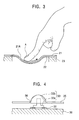
- Fig. 3 is a sectional view of a coordinate input device having an operation surface formed in a concave shape.
- a cover 21 is provided with a concave portion 21A, and a sensor substrate 22 is disposed behind the concave portion 21A and is supported by a base 23.
- the top surface of the concave portion 21A serves as the operation surface for the coordinate input operation.
- the cover 21 and the sensor substrate 22 shown in this figure are constructed similarly to the cover 11 and the sensor substrate 12 shown in Fig. 1 except for the concave portion 21A forming the operation surface, and operations and functions thereof are also similar. Accordingly, detailed explanations thereof are omitted.
- the coordinate input device shown in Fig. 3 when the coordinate input device shown in Fig. 3 is used, since the operation surface is concave and not flat, the user obtains not only the sense of two-dimensional movement but also the sense of vertical movement along the curved surface when he or she slides the operating member A, such as a finger, on the operation surface to perform the coordinate input operation. Thus, the feel of sliding the operating member A can be more easily obtained. Accordingly, also when the coordinate input device shown in Fig. 3 is used, the user can easily follow the amount and direction of cursor movement in accordance with the amount and direction of finger movement, and the cursor can be controlled more finely. Therefore, an excellent operational feel can be obtained.
- a flat region 19 formed at the periphery may be used for providing an additional function other than the normal coordinate input function.
- the additional function may be, for example, a screen-scroll function.
- the present invention may also be applied to any kind of coordinate input devices as long as the operation surface for sliding the operating member is provided.
- the present invention may of course be applied to contact coordinate input devices in which a pair of substrates are disposed such that they oppose each other with a spacer therebetween, the substrates being provided with electrode layers on surfaces opposing each other.
- a coordinate is detected by pressing one of the substrates by an operating member, such as a finger, and bringing the electrode layers into contact with each other.
- the operating member is not limited to the finger, and any kind of operating members may be used as long as it can be slid on the operation surface of the coordinate input device.
- a pen-type operating member may also be used.
- Fig. 4 is a sectional view of a coordinate input device according to the second embodiment
- Fig. 5 is a sectional view of a coordinate input device according to a modification of the second embodiment
- Fig. 6 is a perspective view of the coordinate input device shown in Fig. 4.
- the coordinate input device shown in Figs. 4 and 6 includes a detection sensor unit 32 formed on a base 30 and an operation unit 33 formed on the detection sensor unit 32.
- the operation unit 33 includes a base plate 33a and a hemispherical operation member 33b which is attached on top of the base plate 33a.
- the coordinate input device is installed inside a housing 35 such that the upper side of the operation member 33b projects outside through a hole 36 formed in the housing 35.
- the detection sensor 32 includes four strain gauges 34 which are arranged at a constant interval such that the center of the strain gauges 34 is placed directly under the center of the bottom surface of the base plate 33a.
- the strain gauges 34 are electronically connected to output terminals 37 by electric wires (not shown).
- four legs 33c formed at the four sides of the base plate 33a are placed one on each of the strain gauges 34.
- the top surface of the operation member 33b serves as the operation surface.
- an operating member such as a finger
- slides on the operation surface a pushing force is applied to the operation member 33b and the strain gauges 34 of the detection sensor unit 32 are deformed. Then, a two-dimensional output signal corresponding to the amount of deformation are output through the output terminals 37, and a coordinate input process is performed on the basis of the output signal.
- the operation member 33b including the operation surface is convex upward, the user obtains not only the sense of two-dimensional movement but also the sense of vertical movement along the curved surface when he or she slides his or her finger on the operation surface to perform the coordinate impute operation.
- the amount by which the user has moved his or her finger on the operation surface can be easily recognized from the feel of the finger. Accordingly, the user can easily follow the amount and direction of cursor movement in accordance with the amount and direction of finger movement, and the cursor can be controlled more finely.
- the coordinate input device shown in Fig. 5 includes a detection sensor unit 42 formed on a base 40 and a hemispherical operation unit 43 disposed on the detection sensor unit 42.
- the coordinate input device is installed inside a housing 45 such that the upper side of the operation unit 43 projects outside through a hole 46 formed in the housing 45.
- the detection sensor 42 includes four strain gauges similar to those of the detection sensor unit 32 shown in Fig. 6, the four strain gauges being arranged at a constant interval in a manner similar to Fig. 6, and the operation unit 43 is disposed such that the bottom surface thereof overlaps the strain gauges.
- the coordinate input device shown in Fig. 5 differs from that shown in Fig. 4 in that the strain gauges of the detection sensor unit 42 are pushed by the bottom surface of the hemispherical operation unit 43.
- the operating principal and the operating method are the same as those of the coordinate input device shown in Fig. 4. Accordingly, the coordinate input device shown in Fig. 5 also provides an excellent operational feel similarly to the coordinate input device shown in Fig. 4.
- Figs. 7 and 8 are sectional views showing coordinate input devices according to the present invention having an operation surface formed in a concave shape.
- reference numerals 50 and 60 show bases
- 52 and 62 show detection sensor units
- 53 and 63 show operation units
- 53a shows a base plate
- 53b shows an operation member
- 55 and 65 show housings
- 56 and 66 show holes formed in the housings 55 and 65. Since the coordinate input devices shown in these figures are constructed similarly to those shown in Figs. 4 and 5 except for the shape of the operation units 53 and 63, detailed explanations thereof are omitted.
- the coordinate input devices shown in Figs. 7 and 8 are characterized in that the top surface of the operation member 53b and the top surface the operation unit 63, the top surfaces being formed in a concave shape, are used as the operation surfaces. Since the operation surfaces are formed in a concave shape, similarly to the coordinate input devices shown in Figs. 4 and 5, the user obtains not only the sense of two-dimensional movement but also the sense of vertical movement along the curved surface when he or she slides his or her finger on the operation surface to perform the coordinate impute operation. Thus, the feel of sliding the finger can be more easily obtained. Accordingly, also when the coordinate input devices shown in Figs. 7 and 8 are used, the user can easily follow the amount and direction of cursor movement in accordance with the amount and direction of finger movement, and the cursor can be controlled more finely. Therefore, an excellent operational feel can be obtained.
- the coordinate input device of the present invention in not limited to be used in the following electronic apparatuses.
- the following electronic apparatuses include a coordinate input device according to one of the above-described embodiments.
- Fig. 9 is a perspective view showing a controller for a game device in which the coordinate input device according to the present invention is mounted.
- a controller 70 for a game device is constructed by arranging a coordinate input unit 73 used for performing a coordinate input operation, for example, an operation of inputting a moving direction, and a plurality of button switches 72 on a housing 74.
- a connecting cable 75 for providing connection with the game device (not shown) is connected to the housing 74.
- the coordinate input unit 73 of the controller 70 shown in Fig. 9 contains the coordinate input device according to the present invention, and the game device can be operated by sliding a finger on the coordinate input unit 73. Since the coordinate input unit 73 of the controller 70 constructed as described above includes the coordinate input device of the present invention which has an excellent operational feel, the coordinate input operation can be easily performed.
- Fig. 10 is a perspective view showing an example in which the coordinate input device according to the present invention is used in a mobile phone.
- a mobile phone 80 includes a display 82 disposed at one side of a housing 81, a coordinate input unit 83 disposed in front of the display 82, and a plurality of operation buttons 84 arranged in front of the coordinate input device 83.
- the coordinate input unit 83 of the mobile phone 80 includes the coordinate input device according to the present invention.
- an operation of selecting an object or function shown on the display 82, etc. can be more easily performed by sliding a finger on the coordinate input unit 83.
- Fig. 11 is a plan view showing an example in which the coordinate input device according to the present invention is used in a mobile information terminal.
- a mobile information terminal 90 includes a display 92 which is disposed on a housing 91, a coordinate input unit 93 which is disposed at a central region in front of the display 92, and a plurality of operation buttons 94.
- the coordinate input unit 93 of the mobile information terminal 90 includes the coordinate input device according to the present invention.
- an operation of selecting an object or function shown on the display 92, etc. can be more easily performed by sliding a finger on the coordinate input unit 93.
- Fig. 12 is a perspective view showing an example in which the coordinate input device according to the present invention is used in a notebook personal computer.
- a notebook personal computer 100 includes a main body 101 and a display 102 which is connected to the main body 101 by a hinge at the rear end of the main body 101.
- the main body 101 is provided with a keyboard 103, a coordinate input unit 105 disposed in front of the keyboard 103, and a plurality of push button switches disposed in front of the coordinate input unit 105.
- the coordinate input unit 105 includes the coordinate input device according to the present invention.
- the coordinate input unit 105 includes the coordinate input device according to the present invention, operations of moving a cursor shown on the display 102, selecting an object, etc., can be performed more easily. Accordingly, an operation feel similar to that of a known computer having a rotating ball device can be obtained, and the thickness and weight of the computer can be reduced compared to a computer having a rotating ball device.
- Fig. 13 is a perspective view showing a case in which the coordinate input device according to the present invention is used in a remote controller.
- a remote controller 110 includes an infrared light emitting unit 116 disposed at an end of a housing, a coordinate input unit 115 disposed on the housing, and a plurality of operation buttons 113.
- the coordinate input unit 115 includes the coordinate input device according to the present invention.
- the remote controller 110 can be suitably used for, for example, a television set, a video tape recorder, a car navigation system, etc., and an operation of selecting a function shown in a display of these electronic apparatuses, etc., can be performed more easily.
Abstract
Description
- The present invention relates to coordinate input devices used in computers or game devices for moving a cursor or a character, selecting a function, etc., on a display, and also relates to electronic apparatuses including the coordinate input devices.
- Fig. 14 is a perspective view of a notebook personal computer having a coordinate input device called a touch pad in front of a keyboard. This
computer 200 includes amain body 201 and adisplay 203 which is connected to themain body 201 by a hinge at the rear end of themain body 201. Akeyboard 204, a touch pad (coordinate input device) 205, andoperation buttons 206 are provided on the top surface of themain body 201. Thetouch pad 205 has a flat, rectangular shape and is disposed in front of thekeyboard 204, and theoperation buttons 206 are disposed in front of thetouch pad 205. Thetouch pad 205 is constructed such that a cursor, etc., shown on thedisplay 203 can be operated by sliding an operating member, for example, a finger, on thetouch pad 205. - By using the above-described
touch pad 205, a coordinate input operation, for example, an operation of moving a cursor, can be performed without moving one's hands from their home positions on thekeyboard 204. In addition, since thetouch pad 205 is flat, a thin, space saving computer can be obtained. - However, when the above-described
flat touch pad 205 is used, since the coordinate input operation is performed by moving a finger on thetouch pad 205, there is a problem in that it is difficult for the user to feel the sense of cursor movement compared to when other input devices such as computer mice are used, and a satisfactory operational feel cannot be obtained. - On the other hand, other notebook personal computers having rotating ball devices (trackball devices) instead of the
touch pad 205 shown in Fig. 14 are also known. In such computers, the curser is moved by rotating a ball contained in the rotating ball device. Accordingly, the user can easily obtain the sense of cursor movement by feeling the rotation of the ball with his or her finger, so that the coordinate input operation can be easily performed. However, in order to install the rotating ball device in the computer, a space corresponding to the diameter of the ball must be provided inside the main body of the computer. Therefore, there is a problem in that it is difficult to reduce the thickness of the computer. - Accordingly, in order to solve the above-described problems, an object of the present invention is to provide a coordinate input device with which coordinate input operation can be easily performed with an excellent operational feel, and to provide an electronic apparatus using the coordinate input device.
- In order to attain the above-described objects, the following constructions are used in the present invention.
- A coordinate input device according to the present invention includes a coordinate input unit which performs a coordinate input operation by detecting a position of an operating member on a non-rotating operation surface when the operating member slides on the operation surface, wherein the operation surface is formed in a convex shape, a concave shape, or the shape of a polyhedron.
- In the coordinate input device according to the present invention, since the operation surface is formed in a concave shape, a convex shape, or the shape of a polyhedron, the user can recognize the amount and direction of movement of a finger which slides on the operation surface. Accordingly, the coordinate input operation can be performed more finely, and an excellent operational feel can be obtained.
- In addition, the coordinate input unit of the coordinate input apparatus according to the present invention includes a capacitive sensor substrate which is formed in a concave shape, a convex shape, or the shape of a polyhedron, and which includes a dielectric layer and two electrode layers which are laminated with the dielectric layer therebetween, each electrode layer having a plurality of electrodes arranged in a pattern.
- More specifically, the coordinate input apparatus according to the present invention is constructed by forming an operation surface of a capacitive coordinate input device in a concave shape, a convex shape, or the shape of a polyhedron. The coordinate input operation is performed by sliding the operating member, for example, a finger, on the top surface of the operation surface. Since the user can recognize the amount and direction of movement of the finger which slides on the operation surface, the coordinate input operation can be performed more finely. Therefore, an excellent operational feel can be obtained. In other words, the coordinate input device according to the present invention provides an operating feel equivalent to that of the rotating ball device, and is as space saving as capacitive coordinate input devices.
- In addition, the coordinate input device according to be the present invention may be a contact coordinate input devices in which a pair of substrates provided with electrode layers on surfaces opposing each other are laminated with a spacer therebetween. Also in this case, effects similar to those obtained by the above-described coordinate input device are also obtained.
- According to another aspect of the present invention, a coordinate input device includes a coordinate input unit which performs a coordinate input operation by detecting a pushing force and a sliding direction of an operating member when the operating member slides on an operation surface. The coordinate input means includes a detection sensor unit and an operation unit disposed on the detection sensor unit, the top surface of the operation unit being formed in a concave shape, a convex shape, or the shape of a polyhedron, and the coordinate input means detects the pushing force applied to the operation unit by using the detection sensor unit and outputs a detection signal corresponding to the pushing force.
- In the coordinate input device which is constructed as described above, a coordinate input unit detects the pushing force applied to the operation unit by using the detection sensor unit. Also when the coordinate input device is constructed as described above, similarly to the above-described capacitive coordinate input device, an operating feel equivalent to that of the rotating ball device can be obtained. In addition, since a heavy ball used in the rotating ball device is not necessary, the weight of an electronic apparatus in which the coordinate input device is mounted can be reduced.
- In addition, the above-described coordinate input device may be constructed such that a plurality of strain gauges are radially disposed around the center of the bottom surface of the operation unit at a constant angular interval. In this construction, the strain gauges are used as a coordinate detecting unit of the detection sensor unit used for detecting the coordinate input.
- As described above, according to the coordinate input device of the present invention, the coordinate input operation is performed by sliding the operating member on a capacitive sensor substrate, and the operation surface for sliding the operating member is formed in a concave shape, a convex shape, or the shape of a polyhedron. Accordingly, the user obtains not only the sense of two-dimensional movement but also the sense of vertical movement along the curved surface from his or her finger sliding on the operation surface. Thus, the amount and direction of finger movement can be easily recognized, so that the coordinate input operation can be performed more finely and an excellent operational feel can be obtained. In other words, the coordinate input device according to the present invention provides an operating feel equivalent to that of the rotating ball device, and is as space saving as capacitive coordinate input devices.
- Furthermore, an electronic apparatus according to the present invention includes one of the above-described coordinate input devices. By using the coordinate input device of the present invention, with which the coordinate input operation can be easily performed with an excellent operational feel, as an operation unit for the coordinate input operation, the operability of the electronic apparatus can be improved.
-
- Fig. 1 is a sectional view showing a coordinate input device according to a first embodiment of the present invention;
- Fig. 2 is an exploded perspective view showing a sensor substrate shown in Fig. 1;
- Fig. 3 is a sectional view showing a coordinate input device according to a modification of the first embodiment of the present invention;
- Fig. 4 is a sectional view showing a coordinate input device according to a second embodiment of the present invention;
- Fig. 5 is a sectional view showing a coordinate input device according to a modification of the second embodiment of the present invention;
- Fig. 6 is a perspective view showing the coordinate input device shown in Fig. 4;
- Fig. 7 is a sectional view showing a coordinate input device according to another modification of the second embodiment of the present invention;
- Fig. 8 is a sectional view showing a coordinate input device according to another modification of the second embodiment of the present invention;
- Fig. 9 is a diagram showing a controller for a game device as an example of an electronic apparatus according to the present invention;
- Fig. 10 is a diagram showing a mobile phone as another example of an electronic apparatus according to the present invention;
- Fig. 11 is a diagram showing a mobile information terminal as another example of an electronic apparatus according to the present invention;
- Fig. 12 is a diagram showing a notebook personal computer as another example of an electronic apparatus according to the present invention;
- Fig. 13 is a diagram showing a remote controller as another example of an electronic apparatus according to the present invention; and
- Fig. 14 is a perspective view showing a notebook personal computer including a touch pad as an example of a known coordinate input device.
-
- Embodiments of the present invention will be described below with reference to the accompanying drawings. However, the present invention is not limited to the following embodiments.
- Fig. 1 shows a sectional view of a coordinate input device according to a first embodiment of the present invention. The coordinate input device shown in the figure includes a
cover 11 and asensor substrate 12. Thecover 11 has aconvex portion 11A and is formed on abase 10, and thesensor substrate 12 has the shape corresponding to theconvex portion 11A and is laminated on the bottom surface of theconvex portion 11A (surface facing the base 10) of thecover 11. - As shown in Fig. 2, the
sensor substrate 12 is formed by laminating anupper substrate 14 and alower substrate 15. Theupper substrate 14 is provided with anelectrode layer 16 on the top surface thereof (that is, the surface facing opposite to the lower substrate 15), theelectrode layer 16 including a plurality ofline electrodes 16a arranged parallel to each other in a striped pattern in a plan view. In addition, thelower substrate 15 is provided with anelectrode layer 17 on the top surface thereof, theelectrode layer 17 including a plurality ofelectrodes 17a arranged parallel to each other and perpendicularly to theelectrodes 16a in a striped pattern in a plan view. In addition, at least theupper substrate 14 is formed of a dielectric material, so that the electrode layers 16 and 17 are insulated from each other. - A
control circuit 18 for driving the electrode layers 16 and 17 is disposed on a substrate formed by extending thelower substrate 15 from one end thereof, and, although not shown in the figure, theelectrodes control circuit 18 by electric wires. - The
upper substrate 14 and thelower substrate 15 include aconvex portion 14A and aconvex portion 15A, respectively, at the central position thereof. Theconvex portions substrate 12 formed by laminating the upper andlower substrates convex portion 11A of thecover 11 shown in Fig. 1. The convex portion of thesensor substrate 12 may be formed by laminating thesubstrates upper substrate 14 and thelower substrate 15 are laminated by pressure forming, etc. In addition, although theconvex portions - In the coordinate input device having the above-described construction, the top surface of the
convex portion 11A of thecover 11 in the figure is used as an operation surface, and the change in capacitance between the electrode layers 16 and 17 caused by sliding an operating member A, such as a finger, on the operation surface is output as a detection signal. - In the coordinate input device of the present invention, the coordinate input operation is performed by sliding a finger on the surface of the
convex portion 11A which serves as the operation surface. Accordingly, the sliding friction applied to the user's finger during sliding is larger than that applied when the known,flat touch pad 205 shown in Fig. 14 is used. More specifically, not only the sense of two-dimensional movement caused by moving the finger along the flat surface, but also the sense of vertical movement caused by moving the finger along the convex surface can be obtained at the same time. Accordingly, the user can more reliably feel the subtle sense of coordinate input operation compared to the case in which the known, flat touch pad is used. - More specifically, when, for example, the known
touch pad 205 is used in a computer for moving a cursor, the finger is merely moved along the flat surface, so that the user hardly feels the sense of cursor movement from the finger. Even when the user can feel the sense of cursor movement, it includes only the sense of two-dimensional movement. Accordingly, it is extremely difficult to finely control the amount and direction of cursor movement on the basis of the feel of the finger. On the contrary, according to the coordinate input device of the present invention, since the finger slides on the operation surface having a convex shape, the amount and direction of cursor movement can be recognized on the basis of finger movement in the vertical direction in addition to the two-dimensional movement. Thus, the user can easily recognize the position of his or her finger touching the operation surface. Therefore, the user can easily follow the amount and direction of cursor movement in accordance with the amount and direction of finger movement, and the cursor can be controlled more finely. Accordingly, the operational feel of the coordinate input device can be greatly improved, and therefore the operational feel of the computer can also be improved. - The coordinate input device according to the present embodiment facilitates a coordinate input operation for an extremely small amount of movement, for example, an operation of finely adjusting a cursor position. Since the operation surface is formed in a convex shape, when the user moves his or her finger along the operation surface, the user can easily recognize the amount by which the user has moved his or her finger on the operation surface even if the amount of movement is small. Accordingly, fine position adjustment can be performed on the basis of the feel of the finger.
- In the coordinate input device according to the present embodiment, the operation surface is formed in a convex shape, and the coordinate input operation is performed by sliding the finger on the operation surface. Accordingly, operational feel close to that of the rotating ball device (trackball device) can be obtained. However, in the coordinate input device according to the present embodiment, a relatively large and heavy ball used in the rotating ball device is not necessary and the height can be reduced to half of the diameter of the ball or less, so that the size, especially the thickness, of an electronic apparatus in which the coordinate input device is mounted can be reduced.
- Although the coordinate input device having the operation surface formed in a convex shape is shown in Figs. 1 and 2, the coordinate input device according to the present invention may also have an operation surface formed in a concave shape. Fig. 3 is a sectional view of a coordinate input device having an operation surface formed in a concave shape. In the coordinate input device shown in the figure, a
cover 21 is provided with aconcave portion 21A, and asensor substrate 22 is disposed behind theconcave portion 21A and is supported by abase 23. The top surface of theconcave portion 21A serves as the operation surface for the coordinate input operation. Thecover 21 and thesensor substrate 22 shown in this figure are constructed similarly to thecover 11 and thesensor substrate 12 shown in Fig. 1 except for theconcave portion 21A forming the operation surface, and operations and functions thereof are also similar. Accordingly, detailed explanations thereof are omitted. - Similarly to the coordinate input device shown in Fig. 1, when the coordinate input device shown in Fig. 3 is used, since the operation surface is concave and not flat, the user obtains not only the sense of two-dimensional movement but also the sense of vertical movement along the curved surface when he or she slides the operating member A, such as a finger, on the operation surface to perform the coordinate input operation. Thus, the feel of sliding the operating member A can be more easily obtained. Accordingly, also when the coordinate input device shown in Fig. 3 is used, the user can easily follow the amount and direction of cursor movement in accordance with the amount and direction of finger movement, and the cursor can be controlled more finely. Therefore, an excellent operational feel can be obtained.
- As described above, according to the coordinate input device of the present embodiment, an operational feel similar to that of the known rotating ball device can be obtained, and the problem of thickness and weight of the rotating ball device can be solved.
- In addition, as shown in Fig. 2, a
flat region 19 formed at the periphery may be used for providing an additional function other than the normal coordinate input function. In this case, since the curved portion and the flat portion can be clearly distinguished from each other, regions assigned to such an additional function can be easily found compared to when the operation surface is entirely flat. Accordingly, even when touch typing is performed, misoperation can be prevented. When the coordinate input device is used in a notebook computer, the additional function may be, for example, a screen-scroll function. - Although the capacitive coordinate input device in which the present invention is applied is described above with reference to Figs. 1 to 3, the present invention may also be applied to any kind of coordinate input devices as long as the operation surface for sliding the operating member is provided. For example, the present invention may of course be applied to contact coordinate input devices in which a pair of substrates are disposed such that they oppose each other with a spacer therebetween, the substrates being provided with electrode layers on surfaces opposing each other. In such contact coordinate input devices, a coordinate is detected by pressing one of the substrates by an operating member, such as a finger, and bringing the electrode layers into contact with each other. In addition, according to the present invention, the operating member is not limited to the finger, and any kind of operating members may be used as long as it can be slid on the operation surface of the coordinate input device. For example, a pen-type operating member may also be used.
- Next, a second embodiment of the present invention will be described below with reference to Figs. 4 to 6. Fig. 4 is a sectional view of a coordinate input device according to the second embodiment, and Fig. 5 is a sectional view of a coordinate input device according to a modification of the second embodiment. Fig. 6 is a perspective view of the coordinate input device shown in Fig. 4.
- The coordinate input device shown in Figs. 4 and 6 includes a
detection sensor unit 32 formed on abase 30 and anoperation unit 33 formed on thedetection sensor unit 32. Theoperation unit 33 includes abase plate 33a and ahemispherical operation member 33b which is attached on top of thebase plate 33a. The coordinate input device is installed inside ahousing 35 such that the upper side of theoperation member 33b projects outside through ahole 36 formed in thehousing 35. - In addition, as shown in Fig. 6, the
detection sensor 32 includes fourstrain gauges 34 which are arranged at a constant interval such that the center of the strain gauges 34 is placed directly under the center of the bottom surface of thebase plate 33a. The strain gauges 34 are electronically connected tooutput terminals 37 by electric wires (not shown). In addition, fourlegs 33c formed at the four sides of thebase plate 33a are placed one on each of the strain gauges 34. - In the coordinate input device according to the present embodiment which is constructed as described above, the top surface of the
operation member 33b serves as the operation surface. When an operating member, such as a finger, slides on the operation surface, a pushing force is applied to theoperation member 33b and the strain gauges 34 of thedetection sensor unit 32 are deformed. Then, a two-dimensional output signal corresponding to the amount of deformation are output through theoutput terminals 37, and a coordinate input process is performed on the basis of the output signal. - Similarly to the coordinate input device according to the first embodiment, when the coordinate input device according to the present embodiment is used, since the
operation member 33b including the operation surface is convex upward, the user obtains not only the sense of two-dimensional movement but also the sense of vertical movement along the curved surface when he or she slides his or her finger on the operation surface to perform the coordinate impute operation. Thus, the amount by which the user has moved his or her finger on the operation surface can be easily recognized from the feel of the finger. Accordingly, the user can easily follow the amount and direction of cursor movement in accordance with the amount and direction of finger movement, and the cursor can be controlled more finely. - In addition, the coordinate input device shown in Fig. 5 includes a
detection sensor unit 42 formed on abase 40 and ahemispherical operation unit 43 disposed on thedetection sensor unit 42. The coordinate input device is installed inside ahousing 45 such that the upper side of theoperation unit 43 projects outside through ahole 46 formed in thehousing 45. In addition, although not shown in the figure, thedetection sensor 42 includes four strain gauges similar to those of thedetection sensor unit 32 shown in Fig. 6, the four strain gauges being arranged at a constant interval in a manner similar to Fig. 6, and theoperation unit 43 is disposed such that the bottom surface thereof overlaps the strain gauges. - The coordinate input device shown in Fig. 5 differs from that shown in Fig. 4 in that the strain gauges of the
detection sensor unit 42 are pushed by the bottom surface of thehemispherical operation unit 43. The operating principal and the operating method are the same as those of the coordinate input device shown in Fig. 4. Accordingly, the coordinate input device shown in Fig. 5 also provides an excellent operational feel similarly to the coordinate input device shown in Fig. 4. - Although the coordinate input device having the operation surface formed in a convex shape is shown in Figs. 4 to 6, the coordinate input device according to the present invention may also have an operation surface formed in a concave shape. Figs. 7 and 8 are sectional views showing coordinate input devices according to the present invention having an operation surface formed in a concave shape. In Figs. 7 and 8,
reference numerals housings operation units - The coordinate input devices shown in Figs. 7 and 8 are characterized in that the top surface of the
operation member 53b and the top surface theoperation unit 63, the top surfaces being formed in a concave shape, are used as the operation surfaces. Since the operation surfaces are formed in a concave shape, similarly to the coordinate input devices shown in Figs. 4 and 5, the user obtains not only the sense of two-dimensional movement but also the sense of vertical movement along the curved surface when he or she slides his or her finger on the operation surface to perform the coordinate impute operation. Thus, the feel of sliding the finger can be more easily obtained. Accordingly, also when the coordinate input devices shown in Figs. 7 and 8 are used, the user can easily follow the amount and direction of cursor movement in accordance with the amount and direction of finger movement, and the cursor can be controlled more finely. Therefore, an excellent operational feel can be obtained. - Next, electronic apparatuses according to the present invention will be described below with reference to the accompanying drawings. However, the coordinate input device of the present invention in not limited to be used in the following electronic apparatuses. The following electronic apparatuses include a coordinate input device according to one of the above-described embodiments.
- Fig. 9 is a perspective view showing a controller for a game device in which the coordinate input device according to the present invention is mounted. With reference to the figure, a
controller 70 for a game device is constructed by arranging a coordinateinput unit 73 used for performing a coordinate input operation, for example, an operation of inputting a moving direction, and a plurality of button switches 72 on ahousing 74. In addition, a connectingcable 75 for providing connection with the game device (not shown) is connected to thehousing 74. - The coordinate
input unit 73 of thecontroller 70 shown in Fig. 9 contains the coordinate input device according to the present invention, and the game device can be operated by sliding a finger on the coordinateinput unit 73. Since the coordinateinput unit 73 of thecontroller 70 constructed as described above includes the coordinate input device of the present invention which has an excellent operational feel, the coordinate input operation can be easily performed. - Fig. 10 is a perspective view showing an example in which the coordinate input device according to the present invention is used in a mobile phone. With reference to the figure, a
mobile phone 80 includes adisplay 82 disposed at one side of ahousing 81, a coordinateinput unit 83 disposed in front of thedisplay 82, and a plurality ofoperation buttons 84 arranged in front of the coordinateinput device 83. The coordinateinput unit 83 of themobile phone 80 includes the coordinate input device according to the present invention. - According to the
mobile phone 80 which is constructed as describe above, an operation of selecting an object or function shown on thedisplay 82, etc., can be more easily performed by sliding a finger on the coordinateinput unit 83. - Fig. 11 is a plan view showing an example in which the coordinate input device according to the present invention is used in a mobile information terminal. With reference to the figure, a
mobile information terminal 90 includes adisplay 92 which is disposed on ahousing 91, a coordinateinput unit 93 which is disposed at a central region in front of thedisplay 92, and a plurality ofoperation buttons 94. The coordinateinput unit 93 of themobile information terminal 90 includes the coordinate input device according to the present invention. - According to the
mobile information terminal 90 which is constructed as described above, an operation of selecting an object or function shown on thedisplay 92, etc., can be more easily performed by sliding a finger on the coordinateinput unit 93. - Fig. 12 is a perspective view showing an example in which the coordinate input device according to the present invention is used in a notebook personal computer. With reference to the figure, a notebook
personal computer 100 includes amain body 101 and adisplay 102 which is connected to themain body 101 by a hinge at the rear end of themain body 101. Themain body 101 is provided with akeyboard 103, a coordinateinput unit 105 disposed in front of thekeyboard 103, and a plurality of push button switches disposed in front of the coordinateinput unit 105. The coordinateinput unit 105 includes the coordinate input device according to the present invention. - According to the
computer 100 which is constructed as describe above, since the coordinateinput unit 105 includes the coordinate input device according to the present invention, operations of moving a cursor shown on thedisplay 102, selecting an object, etc., can be performed more easily. Accordingly, an operation feel similar to that of a known computer having a rotating ball device can be obtained, and the thickness and weight of the computer can be reduced compared to a computer having a rotating ball device. - Fig. 13 is a perspective view showing a case in which the coordinate input device according to the present invention is used in a remote controller. With reference to the figure, a
remote controller 110 includes an infraredlight emitting unit 116 disposed at an end of a housing, a coordinateinput unit 115 disposed on the housing, and a plurality ofoperation buttons 113. The coordinateinput unit 115 includes the coordinate input device according to the present invention. - The
remote controller 110 can be suitably used for, for example, a television set, a video tape recorder, a car navigation system, etc., and an operation of selecting a function shown in a display of these electronic apparatuses, etc., can be performed more easily.
Claims (10)
- A coordinate input device comprising:wherein the operation surface is formed in a convex shape, a concave shape, or the shape of a polyhedron.coordinate input means which performs a coordinate input operation by detecting a position of an operating member on a non-rotating operation surface when the operating member slides on the operation surface,
- A coordinate input device according to Claim 1,
wherein the coordinate input means comprises a capacitive sensor substrate which is formed in a concave shape, a convex shape, or the shape of a polyhedron, and which includes a dielectric layer and two electrode layers which are laminated with the dielectric layer therebetween, each electrode layer having a plurality of electrodes arranged in a pattern. - A coordinate input device comprising:wherein the coordinate input means includes a detection sensor unit and an operation unit disposed on the detection sensor unit, the top surface of the operation unit being formed in a concave shape, a convex shape, or the shape of a polyhedron, andcoordinate input means which performs a coordinate input operation by detecting a pushing force and a sliding direction of an operating member when the operating member slides on an operation surface,
wherein the coordinate input means detects the pushing force applied to the operation unit by using the detection sensor unit and outputs a detection signal corresponding to the pushing force. - A coordinate input device according to any of Claims 1 to 3, wherein the operation surface is convex at the side at which the operating member slides thereon, and a flat base for supporting the operation surface is disposed under the operation surface.
- A coordinate input device according to any of Claims 1 to 4, wherein the operation surface is concave at the side at which the operating member slides thereon and a flat base is disposed below the operation surface, the flat base supporting the operation surface at a region outside an effective region in which the operating member slides on the operation surface.
- A coordinate input device according to any of Claims 1 to 5, wherein the detection sensor unit includes a plurality of strain gauges which are arranged around the center of the bottom surface of the operation unit.
- A coordinate input device according to any of Claims 1 to 6, wherein the periphery of the operation surface is formed in a rectangular shape with straight sides.
- A coordinate input device according to Claim 7,
wherein the operation surface includes a flat region at the periphery thereof. - A coordinate input device according to Claim 8,
wherein the flat region is assigned to a particular function other than the coordinate input operation. - An electronic apparatus comprising a coordinate input device according to any of Claims 1 to 9.
Applications Claiming Priority (2)
| Application Number | Priority Date | Filing Date | Title |
|---|---|---|---|
| JP2001282442 | 2001-09-17 | ||
| JP2001282442A JP3971907B2 (en) | 2001-09-17 | 2001-09-17 | Coordinate input device and electronic device |
Publications (2)
| Publication Number | Publication Date |
|---|---|
| EP1293928A2 true EP1293928A2 (en) | 2003-03-19 |
| EP1293928A3 EP1293928A3 (en) | 2004-05-12 |
Family
ID=19106090
Family Applications (1)
| Application Number | Title | Priority Date | Filing Date |
|---|---|---|---|
| EP02020485A Withdrawn EP1293928A3 (en) | 2001-09-17 | 2002-09-12 | Coordinate input device having non-flat operation surface and electronic apparatus |
Country Status (4)
| Country | Link |
|---|---|
| US (1) | US7321361B2 (en) |
| EP (1) | EP1293928A3 (en) |
| JP (1) | JP3971907B2 (en) |
| CN (1) | CN1189812C (en) |
Cited By (10)
| Publication number | Priority date | Publication date | Assignee | Title |
|---|---|---|---|---|
| DE102005002777A1 (en) * | 2005-01-20 | 2006-09-14 | Hermstedt, Jörg | Electronic handset |
| WO2009001193A1 (en) * | 2007-06-22 | 2008-12-31 | Nokia Corporation | Uniform threshold for capacitive sensing |
| GB2471178A (en) * | 2009-06-16 | 2010-12-22 | Intel Corp | Concave, thumb operated touch sensor for one handed operation of a mobile computing device |
| CN104077044A (en) * | 2013-03-27 | 2014-10-01 | 索尼公司 | Input device, input method, and recording medium |
| EP2838198A1 (en) * | 2013-08-15 | 2015-02-18 | RAFI GmbH & Co. KG | Switching device |
| USD732526S1 (en) | 2013-04-16 | 2015-06-23 | Intel Corporation | Computing device with sensor |
| USD745508S1 (en) | 2013-03-15 | 2015-12-15 | Intel Corporation | Computing device with sensor |
| WO2016063062A1 (en) * | 2014-10-24 | 2016-04-28 | Novalia Ltd | Article comprising a capacitive touch device |
| EP2677407A3 (en) * | 2012-06-21 | 2017-08-02 | Wacom Co., Ltd. | Indicator operation detecting device |
| US10389355B2 (en) | 2014-10-17 | 2019-08-20 | Novalia Ltd | Capacitive touch device |
Families Citing this family (68)
| Publication number | Priority date | Publication date | Assignee | Title |
|---|---|---|---|---|
| SE513866C2 (en) * | 1999-03-12 | 2000-11-20 | Spectronic Ab | Hand- or pocket-worn electronic device and hand-controlled input device |
| US20040239622A1 (en) * | 2003-05-30 | 2004-12-02 | Proctor David W. | Apparatus, systems and methods relating to improved user interaction with a computing device |
| US20050052426A1 (en) * | 2003-09-08 | 2005-03-10 | Hagermoser E. Scott | Vehicle touch input device and methods of making same |
| JP2005346402A (en) * | 2004-06-03 | 2005-12-15 | Sony Corp | Input device and electronic apparatus |
| JP4303167B2 (en) * | 2004-06-11 | 2009-07-29 | アルプス電気株式会社 | Input device |
| US7737953B2 (en) * | 2004-08-19 | 2010-06-15 | Synaptics Incorporated | Capacitive sensing apparatus having varying depth sensing elements |
| US7589713B2 (en) * | 2004-10-07 | 2009-09-15 | Alps Electric Co., Ltd. | Capacitive coordinate detection device |
| US20070132740A1 (en) * | 2005-12-09 | 2007-06-14 | Linda Meiby | Tactile input device for controlling electronic contents |
| US7683891B2 (en) * | 2005-12-22 | 2010-03-23 | Synaptics Incorporated | Equalizing reference surface capacitance with uneven thickness |
| US8018431B1 (en) * | 2006-03-29 | 2011-09-13 | Amazon Technologies, Inc. | Page turner for handheld electronic book reader device |
| US9384672B1 (en) | 2006-03-29 | 2016-07-05 | Amazon Technologies, Inc. | Handheld electronic book reader device having asymmetrical shape |
| US8413904B1 (en) | 2006-03-29 | 2013-04-09 | Gregg E. Zehr | Keyboard layout for handheld electronic book reader device |
| US7748634B1 (en) | 2006-03-29 | 2010-07-06 | Amazon Technologies, Inc. | Handheld electronic book reader device having dual displays |
| DE102006037545B4 (en) * | 2006-08-10 | 2015-05-28 | Ferton Holding S.A. | Operating element and method for entering values on a medical device |
| JP2008052559A (en) * | 2006-08-25 | 2008-03-06 | Alps Electric Co Ltd | Electronic apparatus provided with display mechanism |
| US7714839B2 (en) * | 2006-09-29 | 2010-05-11 | Sony Ericsson Mobile Communications Ab | Jog dial for mobile terminal |
| US8264463B2 (en) | 2007-09-21 | 2012-09-11 | Sony Corporation | Input device and electronic apparatus |
| JP2009217804A (en) * | 2007-09-21 | 2009-09-24 | Sony Corp | Input device and electronic apparatus |
| US8223130B2 (en) * | 2007-11-28 | 2012-07-17 | Sony Corporation | Touch-sensitive sheet member, input device and electronic apparatus |
| JP5345336B2 (en) * | 2008-04-15 | 2013-11-20 | 株式会社ジャパンディスプレイ | Input device and display device including the same |
| JP4523049B2 (en) | 2008-04-25 | 2010-08-11 | Smk株式会社 | Instruction input device |
| US20100026654A1 (en) * | 2008-07-29 | 2010-02-04 | Honeywell International Inc. | Coordinate input device |
| US8427424B2 (en) | 2008-09-30 | 2013-04-23 | Microsoft Corporation | Using physical objects in conjunction with an interactive surface |
| US20100126784A1 (en) * | 2008-11-26 | 2010-05-27 | Honeywell International Inc. | Continuously variable knob input device |
| US9317140B2 (en) | 2009-03-30 | 2016-04-19 | Microsoft Technology Licensing, Llc | Method of making a multi-touch input device for detecting touch on a curved surface |
| US8982051B2 (en) | 2009-03-30 | 2015-03-17 | Microsoft Technology Licensing, Llc | Detecting touch on a surface |
| JP5225178B2 (en) * | 2009-04-03 | 2013-07-03 | 信越ポリマー株式会社 | Capacitance sensor and manufacturing method thereof |
| US9262063B2 (en) * | 2009-09-02 | 2016-02-16 | Amazon Technologies, Inc. | Touch-screen user interface |
| US8451238B2 (en) | 2009-09-02 | 2013-05-28 | Amazon Technologies, Inc. | Touch-screen user interface |
| US8471824B2 (en) | 2009-09-02 | 2013-06-25 | Amazon Technologies, Inc. | Touch-screen user interface |
| US8624851B2 (en) | 2009-09-02 | 2014-01-07 | Amazon Technologies, Inc. | Touch-screen user interface |
| US8730309B2 (en) | 2010-02-23 | 2014-05-20 | Microsoft Corporation | Projectors and depth cameras for deviceless augmented reality and interaction |
| KR101375476B1 (en) | 2010-05-13 | 2014-03-18 | 알프스 덴키 가부시키가이샤 | Capacitive input device |
| KR101451493B1 (en) | 2010-05-13 | 2014-10-15 | 알프스 덴키 가부시키가이샤 | Capacitive input device |
| US9329469B2 (en) | 2011-02-17 | 2016-05-03 | Microsoft Technology Licensing, Llc | Providing an interactive experience using a 3D depth camera and a 3D projector |
| US9480907B2 (en) | 2011-03-02 | 2016-11-01 | Microsoft Technology Licensing, Llc | Immersive display with peripheral illusions |
| GB2490486A (en) * | 2011-04-26 | 2012-11-07 | Sound Infinity Ltd | Stereo audio output for data input to an electronic device |
| GB2490485A (en) * | 2011-04-26 | 2012-11-07 | Sound Infinity Ltd | User Interface with a concave surface for an Electronic Device |
| US8826190B2 (en) | 2011-05-27 | 2014-09-02 | Google Inc. | Moving a graphical selector |
| US8656315B2 (en) | 2011-05-27 | 2014-02-18 | Google Inc. | Moving a graphical selector |
| US9597587B2 (en) | 2011-06-08 | 2017-03-21 | Microsoft Technology Licensing, Llc | Locational node device |
| WO2013005432A1 (en) | 2011-07-04 | 2013-01-10 | 東海ゴム工業株式会社 | External operation detection structure body |
| JP2013025704A (en) * | 2011-07-25 | 2013-02-04 | Tokai Rubber Ind Ltd | Detection structure for external operation |
| JP5312541B2 (en) * | 2011-09-07 | 2013-10-09 | 信越ポリマー株式会社 | Capacitance sensor |
| JP2013058117A (en) * | 2011-09-09 | 2013-03-28 | Alps Electric Co Ltd | Input device |
| JP5748082B2 (en) * | 2011-10-18 | 2015-07-15 | フィッシャー テクノロジー ピーティーイー. リミテッド | Molding method |
| JP5839470B2 (en) | 2012-01-31 | 2016-01-06 | 富士通コンポーネント株式会社 | Pointing device and manufacturing method thereof |
| JP2013171400A (en) * | 2012-02-20 | 2013-09-02 | Denso Corp | Input device |
| JP5840980B2 (en) | 2012-02-29 | 2016-01-06 | 株式会社日本自動車部品総合研究所 | Operation position detection device and in-vehicle device |
| JP6199541B2 (en) * | 2012-04-19 | 2017-09-20 | 富士通コンポーネント株式会社 | Touch input device |
| JP5602182B2 (en) * | 2012-04-27 | 2014-10-08 | 株式会社日立ビルシステム | Elevator operation panel, elevator device, and elevator operation panel replacement method |
| US20130285735A1 (en) * | 2012-04-30 | 2013-10-31 | Delphi Technologies, Inc. | Operator control assembly |
| US8656296B1 (en) | 2012-09-27 | 2014-02-18 | Google Inc. | Selection of characters in a string of characters |
| KR101663763B1 (en) * | 2013-07-31 | 2016-10-07 | 엘지디스플레이 주식회사 | Display device with touch screen |
| WO2015083815A1 (en) * | 2013-12-06 | 2015-06-11 | ポリマテック・ジャパン株式会社 | Touch sensor and touch panel device |
| GB2521669A (en) * | 2013-12-30 | 2015-07-01 | Nokia Technologies Oy | An apparatus for a touch sensor structure |
| US10073569B2 (en) * | 2014-01-28 | 2018-09-11 | Apple Inc. | Integrated polarizer and conductive material |
| US9395858B2 (en) * | 2014-07-22 | 2016-07-19 | Pixart Imaging Inc. | Capacitive finger navigation device with hybrid mode and operating method thereof |
| KR101762218B1 (en) | 2014-11-10 | 2017-07-27 | 가부시키가이샤 원더 퓨쳐 코포레이션 | Touch panel, touch-panel manufacturing method, and touch-panel-integrated display device |
| JP6282223B2 (en) * | 2014-12-27 | 2018-02-21 | アルプス電気株式会社 | Input device |
| JP6095706B2 (en) * | 2015-02-04 | 2017-03-15 | レノボ・シンガポール・プライベート・リミテッド | Pointing device, keyboard assembly and portable computer. |
| JP6506119B2 (en) * | 2015-06-29 | 2019-04-24 | グンゼ株式会社 | Touch input device |
| US10386940B2 (en) | 2015-10-30 | 2019-08-20 | Microsoft Technology Licensing, Llc | Touch sensing of user input device |
| JP2018190268A (en) * | 2017-05-10 | 2018-11-29 | 富士フイルム株式会社 | Touch type operation device, operation method thereof, and operation program |
| DE102017113661B4 (en) * | 2017-06-21 | 2021-03-04 | Bcs Automotive Interface Solutions Gmbh | Motor vehicle operating device |
| US10946612B2 (en) * | 2018-08-27 | 2021-03-16 | Tactotek Oy | Integrated multilayer structure for use in sensing applications and method for manufacturing thereof |
| JP7265878B2 (en) * | 2019-02-12 | 2023-04-27 | アルプスアルパイン株式会社 | input device |
| US20210283465A1 (en) * | 2020-03-10 | 2021-09-16 | Life Fitness, Llc | Systems and devices for controlling fitness machines |
Family Cites Families (18)
| Publication number | Priority date | Publication date | Assignee | Title |
|---|---|---|---|---|
| US4084451A (en) * | 1976-07-02 | 1978-04-18 | Ward John Lionel R | Drive-transmitting mechanisms |
| US4550221A (en) * | 1983-10-07 | 1985-10-29 | Scott Mabusth | Touch sensitive control device |
| US5335557A (en) * | 1991-11-26 | 1994-08-09 | Taizo Yasutake | Touch sensitive input control device |
| US5367199A (en) * | 1992-05-01 | 1994-11-22 | Triax Technologies | Sliding contact control switch pad |
| US5942733A (en) * | 1992-06-08 | 1999-08-24 | Synaptics, Inc. | Stylus input capacitive touchpad sensor |
| JPH07160396A (en) * | 1993-12-09 | 1995-06-23 | Nec Corp | Pointing device |
| EP0660258B1 (en) * | 1993-12-20 | 2000-03-08 | Seiko Epson Corporation | Electronic pointing device |
| US6001486A (en) * | 1994-07-29 | 1999-12-14 | Donnelly Corporation | Transparent substrate with diffuser surface |
| SE515663C2 (en) * | 1996-08-23 | 2001-09-17 | Ericsson Telefon Ab L M | Touch screen and use of touch screen |
| US6184865B1 (en) * | 1996-10-23 | 2001-02-06 | International Business Machines Corporation | Capacitive pointing stick apparatus for symbol manipulation in a graphical user interface |
| US5995083A (en) * | 1996-11-20 | 1999-11-30 | Alps Electric Co., Ltd. | Coordinates input apparatus |
| DE19708450A1 (en) * | 1997-03-03 | 1998-09-17 | Ericsson Telefon Ab L M | Device for controlling a position indicator on a visual display |
| US6369803B2 (en) * | 1998-06-12 | 2002-04-09 | Nortel Networks Limited | Active edge user interface |
| US6388655B1 (en) * | 1999-11-08 | 2002-05-14 | Wing-Keung Leung | Method of touch control of an input device and such a device |
| US6535201B1 (en) * | 1999-12-17 | 2003-03-18 | International Business Machines Corporation | Method and system for three-dimensional topographical modeling |
| CN1225642C (en) * | 2001-03-14 | 2005-11-02 | 新田株式会社 | Electrical capacitance sensor |
| US20020149566A1 (en) * | 2001-04-16 | 2002-10-17 | Sarkissian Arthur H. | Key-surround module inputting device |
| US20040017355A1 (en) * | 2002-07-24 | 2004-01-29 | Youngtack Shim | Cursor control systems and methods |
-
2001
- 2001-09-17 JP JP2001282442A patent/JP3971907B2/en not_active Expired - Fee Related
-
2002
- 2002-09-11 CN CNB02131604XA patent/CN1189812C/en not_active Expired - Fee Related
- 2002-09-12 EP EP02020485A patent/EP1293928A3/en not_active Withdrawn
- 2002-09-16 US US10/244,702 patent/US7321361B2/en not_active Expired - Lifetime
Non-Patent Citations (1)
| Title |
|---|
| None * |
Cited By (15)
| Publication number | Priority date | Publication date | Assignee | Title |
|---|---|---|---|---|
| DE102005002777A1 (en) * | 2005-01-20 | 2006-09-14 | Hermstedt, Jörg | Electronic handset |
| CN101821700B (en) * | 2007-06-22 | 2012-07-18 | 诺基亚公司 | Uniform threshold for capacitive sensing |
| WO2009001193A1 (en) * | 2007-06-22 | 2008-12-31 | Nokia Corporation | Uniform threshold for capacitive sensing |
| US8063330B2 (en) | 2007-06-22 | 2011-11-22 | Nokia Corporation | Uniform threshold for capacitive sensing |
| US8674951B2 (en) | 2009-06-16 | 2014-03-18 | Intel Corporation | Contoured thumb touch sensor apparatus |
| GB2471178B (en) * | 2009-06-16 | 2012-01-04 | Intel Corp | Contoured thumb touch sensor apparatus |
| GB2471178A (en) * | 2009-06-16 | 2010-12-22 | Intel Corp | Concave, thumb operated touch sensor for one handed operation of a mobile computing device |
| EP2677407A3 (en) * | 2012-06-21 | 2017-08-02 | Wacom Co., Ltd. | Indicator operation detecting device |
| USD745508S1 (en) | 2013-03-15 | 2015-12-15 | Intel Corporation | Computing device with sensor |
| CN104077044A (en) * | 2013-03-27 | 2014-10-01 | 索尼公司 | Input device, input method, and recording medium |
| USD732526S1 (en) | 2013-04-16 | 2015-06-23 | Intel Corporation | Computing device with sensor |
| EP2838198A1 (en) * | 2013-08-15 | 2015-02-18 | RAFI GmbH & Co. KG | Switching device |
| US10389355B2 (en) | 2014-10-17 | 2019-08-20 | Novalia Ltd | Capacitive touch device |
| WO2016063062A1 (en) * | 2014-10-24 | 2016-04-28 | Novalia Ltd | Article comprising a capacitive touch device |
| GB2531607B (en) * | 2014-10-24 | 2018-04-18 | Novalia Ltd | Article incorporating a capacitive touch device and having a non-flat surface |
Also Published As
| Publication number | Publication date |
|---|---|
| CN1405666A (en) | 2003-03-26 |
| US7321361B2 (en) | 2008-01-22 |
| US20030071784A1 (en) | 2003-04-17 |
| CN1189812C (en) | 2005-02-16 |
| JP3971907B2 (en) | 2007-09-05 |
| EP1293928A3 (en) | 2004-05-12 |
| JP2003091360A (en) | 2003-03-28 |
Similar Documents
| Publication | Publication Date | Title |
|---|---|---|
| US7321361B2 (en) | Coordinate input device having non-flat operation surface and electronic apparatus | |
| US11511186B2 (en) | Controller with sensor-rich controls | |
| US9563317B2 (en) | Capacitive control panel | |
| US9632608B2 (en) | Selective input signal rejection and modification | |
| USRE41443E1 (en) | Input device which allows button input operation and coordinate input operation to be performed in the same operation plane | |
| US7639234B2 (en) | Capacitive sensing and absolute position mapping in displacement type pointing devices | |
| US8816978B2 (en) | Seesaw touchpad with horizontal direction hinge | |
| US20110254801A1 (en) | Three-dimensional contact-sensitive feature for electronic devices | |
| US20020180707A1 (en) | Input device capable of button input and coordinate input on the same operating surface | |
| US20140002358A1 (en) | Compact capacitive track pad | |
| US20060192754A1 (en) | Hybrid pointing device | |
| JP2002123363A5 (en) | ||
| US10353485B1 (en) | Multifunction input device with an embedded capacitive sensing layer | |
| JP2008198205A (en) | Tilting touch control panel | |
| JPH0377222A (en) | Input device | |
| WO2006071355A2 (en) | Puck-based pointing device that provides multiple buttons | |
| CN115129222A (en) | Continuous touch input on multiple independent surfaces | |
| EP1672472A1 (en) | Data input device, information equipment, information equipment control method, and computer program | |
| JP2003036132A (en) | Coordinate input device and electronic equipment | |
| JP2000029607A (en) | Keyboard | |
| JP2000029622A (en) | Pointing device | |
| JPH04319722A (en) | Input device | |
| AU2015271962A1 (en) | Interpreting touch contacts on a touch surface |
Legal Events
| Date | Code | Title | Description |
|---|---|---|---|
| PUAI | Public reference made under article 153(3) epc to a published international application that has entered the european phase |
Free format text: ORIGINAL CODE: 0009012 |
|
| AK | Designated contracting states |
Designated state(s): AT BE BG CH CY CZ DE DK EE ES FI FR GB GR IE IT LI LU MC NL PT SE SK TR Kind code of ref document: A2 Designated state(s): AT BE BG CH CY CZ DE DK EE ES FI FR GB GR IE IT LI LU MC NL PT SE SK TR |
|
| AX | Request for extension of the european patent |
Extension state: AL LT LV MK RO SI |
|
| RIC1 | Information provided on ipc code assigned before grant |
Ipc: 7G 06F 3/033 B Ipc: 7G 06K 11/18 A |
|
| PUAL | Search report despatched |
Free format text: ORIGINAL CODE: 0009013 |
|
| AK | Designated contracting states |
Kind code of ref document: A3 Designated state(s): AT BE BG CH CY CZ DE DK EE ES FI FR GB GR IE IT LI LU MC NL PT SE SK TR |
|
| AX | Request for extension of the european patent |
Extension state: AL LT LV MK RO SI |
|
| 17P | Request for examination filed |
Effective date: 20040602 |
|
| 17Q | First examination report despatched |
Effective date: 20040901 |
|
| AKX | Designation fees paid |
Designated state(s): DE FR GB |
|
| RAP1 | Party data changed (applicant data changed or rights of an application transferred) |
Owner name: ALPS ALPINE CO., LTD. |
|
| STAA | Information on the status of an ep patent application or granted ep patent |
Free format text: STATUS: THE APPLICATION IS DEEMED TO BE WITHDRAWN |
|
| 18D | Application deemed to be withdrawn |
Effective date: 20190411 |