EP1610145A1 - Antenna orientation device - Google Patents
Antenna orientation device Download PDFInfo
- Publication number
- EP1610145A1 EP1610145A1 EP04447150A EP04447150A EP1610145A1 EP 1610145 A1 EP1610145 A1 EP 1610145A1 EP 04447150 A EP04447150 A EP 04447150A EP 04447150 A EP04447150 A EP 04447150A EP 1610145 A1 EP1610145 A1 EP 1610145A1
- Authority
- EP
- European Patent Office
- Prior art keywords
- antenna
- positioning
- computer
- axis
- satellite
- Prior art date
- Legal status (The legal status is an assumption and is not a legal conclusion. Google has not performed a legal analysis and makes no representation as to the accuracy of the status listed.)
- Withdrawn
Links
Images

Classifications
-
- G—PHYSICS
- G01—MEASURING; TESTING
- G01S—RADIO DIRECTION-FINDING; RADIO NAVIGATION; DETERMINING DISTANCE OR VELOCITY BY USE OF RADIO WAVES; LOCATING OR PRESENCE-DETECTING BY USE OF THE REFLECTION OR RERADIATION OF RADIO WAVES; ANALOGOUS ARRANGEMENTS USING OTHER WAVES
- G01S3/00—Direction-finders for determining the direction from which infrasonic, sonic, ultrasonic, or electromagnetic waves, or particle emission, not having a directional significance, are being received
- G01S3/02—Direction-finders for determining the direction from which infrasonic, sonic, ultrasonic, or electromagnetic waves, or particle emission, not having a directional significance, are being received using radio waves
- G01S3/14—Systems for determining direction or deviation from predetermined direction
- G01S3/38—Systems for determining direction or deviation from predetermined direction using adjustment of real or effective orientation of directivity characteristic of an antenna or an antenna system to give a desired condition of signal derived from that antenna or antenna system, e.g. to give a maximum or minimum signal
- G01S3/42—Systems for determining direction or deviation from predetermined direction using adjustment of real or effective orientation of directivity characteristic of an antenna or an antenna system to give a desired condition of signal derived from that antenna or antenna system, e.g. to give a maximum or minimum signal the desired condition being maintained automatically
-
- H—ELECTRICITY
- H01—ELECTRIC ELEMENTS
- H01Q—ANTENNAS, i.e. RADIO AERIALS
- H01Q1/00—Details of, or arrangements associated with, antennas
- H01Q1/12—Supports; Mounting means
- H01Q1/125—Means for positioning
-
- H—ELECTRICITY
- H01—ELECTRIC ELEMENTS
- H01Q—ANTENNAS, i.e. RADIO AERIALS
- H01Q3/00—Arrangements for changing or varying the orientation or the shape of the directional pattern of the waves radiated from an antenna or antenna system
- H01Q3/02—Arrangements for changing or varying the orientation or the shape of the directional pattern of the waves radiated from an antenna or antenna system using mechanical movement of antenna or antenna system as a whole
- H01Q3/08—Arrangements for changing or varying the orientation or the shape of the directional pattern of the waves radiated from an antenna or antenna system using mechanical movement of antenna or antenna system as a whole for varying two co-ordinates of the orientation
Definitions
- the present invention relates to an orientation device on a satellite geostationary antenna, an appropriate receiving antenna mounted on a mobile platform, for example a vehicle.
- Antenna orientation devices are known in the state of the art. They are generally oriented on the transmitter according to the intensity of the signal picked up.
- GB-2159335 discloses in particular a method and apparatus to automatically follow a communication satellite using the antenna reception. It is in this case a satellite dish mounted on a mobile platform, like a ship.
- the signals received from sensors of the azimuth, the elevation and inclination as well as the reception signal are sent to a calculator which controls the antenna so as to compensate for the movements of the platform and according to a spiral sweep.
- the present invention seeks to provide a different and simple device for the orientation of a receiving antenna, such as an antenna parabolic or similar for the reception of audio-visual signals. It's about a device that uses known technologies of the GPS type (Global Positioning System). Given the use of this technology, it is not necessary to use the received signal strength to position the antenna optimal.
- GPS type Global Positioning System
- the antenna orientation device has at least one GPS positioning system which determines the coordinates of the position of the antenna on the earth, a means that determines the orientation of the antenna with respect to the magnetic north, a motor of positioning of the antenna with regard to its azimuth, a motor of positioning of the antenna with regard to its elevation, an interface user for starting said antenna orientation device and the choice of a geostationary satellite as well as a calculator which controls with the help of known per se the positioning engines according to the information received from the various sensors and the choice of geostationary satellite to point said antenna substantially on said satellite.
- the device of the invention comprises still a position detector with regard to the azimuth and a detector of elevation position.
- These detectors are preferably for reasons of ease, home position detectors. It is understood that in case omission of these detectors, it is necessary to ensure, for reasons of precision, the antenna is in the rest position or zero position predetermined before each new positioning calculation.
- the means of determining the orientation of the antenna relative to the north Magnetic is advantageously a compass known per se.
- the antenna positioning motor according to the azimuth determined by the calculator advantageously consists of a motor allowing a rotation approximately 360 degrees of the antenna around an axis normal to the mobile platform on which the antenna is mounted.
- the motor positioning the antenna according to the determined elevation by the computer advantageously consists of a motor allowing a rotation up to 180 degrees from the platform around an axis perpendicular to the axis normal to said mobile platform.
- the device of the invention may also comprise a detector of level in an axis and, preferably, in an axis perpendicular thereto. In the absence of these level detectors, it is obvious that there is a need to ensure that that the platform is in a substantially horizontal position.
- the choice of the geostationary satellite is fixed beforehand.
- the user interface is only used to start or stop the device of the invention.
- the user interface consists of a multi-position selector or a set of connected pushbuttons by means known per se to the computer for the transmission of the information of the choice of the desired geostationary satellite.
- the links between the user interface and the calculator and between the calculator and controls of positioning motors as well as between various sensors or detectors and the calculator can be of various types known in itself. It can, of course, be cable connections or connections without such as "Blue Tooth” or infra-red connections or others or combinations thereof.
- the device of the invention makes it possible to automatically position an antenna orientable to easily, quickly and reliably point to a satellite geostationary chosen by the user. It calculates the appropriate orientation from information received from the GPS system, from the compass and corrects the calculation, the where appropriate, using the information received from the level detectors, and then controls the positioning motors of the receiving antenna in order to to point the antenna to the desired geostationary satellite.
- the device the invention is particularly suitable for travelers or professionals riders, such as truck drivers, caravan holiday mobile home, because it allows them to easily pick up when they are stopped, information and in particular audio-visual broadcasts geostationary satellites.
- this therefore also provides a method for orienting a reception antenna, in particular an antenna of reception mounted on a mobile platform, substantially on a satellite geostationary process characterized by the following steps: (i) selecting a geostationary satellite, (ii) location of the antenna by a positioning of the GPS type, (iii) determining the orientation of said antenna relative to magnetic north, (iv) calculation of azimuth angle and angle elevation of the antenna according to the information received from the GPS system and various sensors, and (v) control of antenna positioning motors according to the calculated azimuth angle and the calculated elevation angle.
- the method comprises a step of correcting the calculation in data function received from level detectors along a certain axis and a perpendicular axis this one.
- FIG. 1 there is a geostationary satellite 1 and an antenna parabolic 3 mounted on a base 5 integral with a vehicle, for example.
- the antenna is controlled by two positioning motors: a first positioning engine 7 according to the calculated azimuth and a second engine of positioning 9 according to a calculated elevation angle.
- the engine of positioning 7 advantageously allows rotation of the antenna substantially 360 degrees around an axis normal to the platform (no shown) on which the antenna is mounted.
- the engine of positioning 9 it suffices that it allows a rotation of the antenna going up to substantially 180 degrees, relative to said platform, around an axis perpendicular to the axis of rotation of the positioning motor 7.
- the interface 1 further distinguishes a location device of the GPS 11 type which allows the location of the antenna on the earth, as well as a compass 13 which determines the orientation of the antenna with respect to magnetic north.
- the interface user has the reference mark 15. It has a switch on / off 17 and a multiple choice selector 19.
- the GPS system 11, the compass 13 and the user interface 15 are connected to a computer 21. This one control in turn the positioning motors 7 and 9 via known means, namely power control modules 23 and 25, respectively.
- the computer 21 can be a calculator specifically intended for the device of the invention, but that it can also be integrated into a other apparatus, namely to be part of the vehicle's own calculator on the which is mounted the antenna.
- the device of the invention uses certain features of the computer of said vehicle.
- the user interface 15 may consist of a fixed module integral with the table of edge of the vehicle equipped with the device of the invention or consist of a module portable or removable connected to the computer 21, either by wire or wirelessly; in this last case, it is a link of the type "Blue Tooth” (trade name) or by infrared.
- the device of the invention may also advantageously comprise level detectors 27 and 29 along two essentially perpendicular axes X and Y, respectively.
- the device of the invention comprises still a rest position detector for the azimuth 31 and a detector of rest position for elevation 33, to facilitate proper positioning of the antenna according to the information received.
- the user starts the device of the invention using the switch 17. He then chooses the satellite on which he wants to position himself, spotted for example by a number on the selector 19. It is understood that the selection of satellite can be done in various ways, for example, a selector mechanical, the choice of a number on a remote control, or the choice in a computer program menu.
- the user confirms his choice and asks the computer 21 to position the antenna 3.
- the calculator interrogates the position detectors 31, 33 which confirm whether the antenna is in the position of rest or not.
- the computer 21 controls the motors of matching positions 7 and 9 via power modules 23 and 25 in order to return the antenna 3 to the rest position.
- the calculator interrogates the various sensors from which it receives the following information: from the GPS 11 system, it receives the longitude and latitude; of the compass 13, it receives the orientation of the antenna by magnetic north ratio; of the x27 level detector it gets the value of the inclination along the X axis and the level detector y 29, the value of the inclination along the Y axis.
- Calculator 21 calculates (see, for example, the program "Opensource” Satpos), according to all these parameters, the azimuth and the elevation to be given to the antenna, by means of an algorithm known per se.
- This algorithm takes into account the position of the geostationary satellite chosen, the longitude and latitude of the antenna, the orientation of the antenna real north (which is corrected magnetic north) and, where appropriate, the inclination along the X and Y axes.
- the computer controls the motors 7 and 9, for example according to the following sequence: (i) position the elevation motor at the calculated angle and (ii) position the azimuth motor at the calculated angle and check that the compass confirms the angle.
- the computer returns the antenna 3 to the rest position, for example, as follows: control the elevation motor 9 until a position elevation is reached which facilitates rotation of the antenna; then order the azimuth motor 7 until the rest position with regard to the azimuth is detected and then again control the elevation motor 9 until the home position is detected.
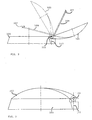
- FIG. 2 diagrammatically represents an antenna according to the invention, in various open positions. It comprises a receiving antenna 103 essentially parabolic or of equivalent form for the reception of audio-visual signals, articulated on a base 105 secured to a vehicle (not shown), such as the cabin of a truck for example, and a receiver 107 in his focus, mounted at the end of an arm 109.
- the parabola 103 rotates relative at the base 105 by means of a hinge with axis 111 (lifting movement) essentially in the upper plane of the base 105, arranged at the top lower part of the dish 103.
- the arm 109 carrying the receiver 107 is connected to the lower vertex of the parable 103, is retractable in the hollow of the parabola 103 when it is folded on its base 105 for a reduced bulk (see FIGS. 3 and 4), and is brought and maintained in position fixed in relation to the parable 103, namely in its home, when it is in open position of reception, using a linkage provided with a spring recall.
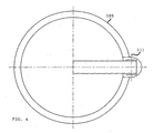
- the closed position of Figures 3 and 4 corresponds to the rest position.
- Figure 5 shows the antenna in the open position; this may be the rest position with respect to azimuth.
- the hinge axis 111 is mounted on a perpendicular axis 113 which still allows a rotation of the parabola 103 with its receiver 107 around this axis 113, relative to the base 105, to allow rotation of azimuth.
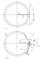
- the FIG. 6 represents various receiving positions of the parabola 103 with its receiver 109.
- the rotation about the axis 111 can advantageously be controlled by a axial gear motor (9) housed in the hinge axis 111.
- the rotation around of the axis 113 is advantageously controlled by a drive group comprising motor and gearbox (7) housed in the hinge or in the base 105.
Abstract
Description
La présente invention concerne un dispositif d'orientation sur un satellite géostationnaire, d'une antenne de réception appropriée montée sur une plateforme mobile, par exemple un véhicule.The present invention relates to an orientation device on a satellite geostationary antenna, an appropriate receiving antenna mounted on a mobile platform, for example a vehicle.
Des dispositifs d'orientation d'antenne sont connus dans l'état de la technique. Ils s'orientent généralement sur l'émetteur selon l'intensité du signal capté.Antenna orientation devices are known in the state of the art. They are generally oriented on the transmitter according to the intensity of the signal picked up.
On connaít notamment par le document GB-2159335 un procédé et appareillage pour automatiquement suivre un satellite de communication à l'aide de l'antenne de réception. Il s'agit dans ce cas d'une antenne parabolique montée sur une plateforme mobile, tel un navire. Les signaux reçus de capteurs de l'azimut, de l'élévation et de l'inclinaison ainsi que le signal de réception sont envoyés à un calculateur qui commande l'antenne de façon à compenser les mouvements de la plateforme et selon un balayage en forme de spirale.GB-2159335 discloses in particular a method and apparatus to automatically follow a communication satellite using the antenna reception. It is in this case a satellite dish mounted on a mobile platform, like a ship. The signals received from sensors of the azimuth, the elevation and inclination as well as the reception signal are sent to a calculator which controls the antenna so as to compensate for the movements of the platform and according to a spiral sweep.
La présente invention cherche à fournir un dispositif différent et simple pour l'orientation d'une antenne de réception, comme par exemple une antenne parabolique ou assimilable pour la réception de signaux audio-visuels. Il s'agit d'un dispositif qui fait appel aux technologies connues du type GPS (Global Positioning System). Vu l'utilisation de cette technologie, il n'est pas nécessaire de faire appel à l'intensité du signal reçu afin de positionner l'antenne de façon optimale.The present invention seeks to provide a different and simple device for the orientation of a receiving antenna, such as an antenna parabolic or similar for the reception of audio-visual signals. It's about a device that uses known technologies of the GPS type (Global Positioning System). Given the use of this technology, it is not necessary to use the received signal strength to position the antenna optimal.
Conformément à la présente invention, le dispositif d'orientation d'antenne comporte au moins un système de positionnement GPS qui détermine les coordonnées de position de l'antenne sur la terre, un moyen qui détermine l'orientation de l'antenne par rapport au nord magnétique, un moteur de positionnement de l'antenne pour ce qui concerne son azimut, un moteur de positionnement de l'antenne pour ce qui concerne son élévation, un interface utilisateur pour le démarrage dudit dispositif d'orientation d'antenne et le choix d'un satellite géostationnaire ainsi qu'un calculateur qui pilote à l'aide de moyens connus en soi les moteurs de positionnement en fonction des informations reçues des divers capteurs et du choix de satellite géostationnaire afin de pointer ladite antenne substantiellement sur ledit satellite.According to the present invention, the antenna orientation device has at least one GPS positioning system which determines the coordinates of the position of the antenna on the earth, a means that determines the orientation of the antenna with respect to the magnetic north, a motor of positioning of the antenna with regard to its azimuth, a motor of positioning of the antenna with regard to its elevation, an interface user for starting said antenna orientation device and the choice of a geostationary satellite as well as a calculator which controls with the help of known per se the positioning engines according to the information received from the various sensors and the choice of geostationary satellite to point said antenna substantially on said satellite.
Selon une forme d'exécution préférée, le dispositif de l'invention comporte encore un détecteur de position pour ce qui concerne l'azimut et un détecteur de position d'élévation. Ces détecteurs sont, de préférence, pour des raisons de facilité, des détecteurs de position de repos. Il est bien entendu qu'en cas d'omission de ces détecteurs, il y a lieu de veiller, pour des raisons de précision, à ce que l'antenne se retrouve en position de repos ou position zéro prédéterminée avant chaque nouveau calcul de positionnement.According to a preferred embodiment, the device of the invention comprises still a position detector with regard to the azimuth and a detector of elevation position. These detectors are preferably for reasons of ease, home position detectors. It is understood that in case omission of these detectors, it is necessary to ensure, for reasons of precision, the antenna is in the rest position or zero position predetermined before each new positioning calculation.
Le moyen de détermination de l'orientation de l'antenne par rapport au nord magnétique consiste avantageusement en une boussole connue en soi.The means of determining the orientation of the antenna relative to the north Magnetic is advantageously a compass known per se.
Le moteur de positionnement de l'antenne selon l'azimut déterminé par le calculateur consiste avantageusement en un moteur permettant une rotation d'approximativement 360 degrés de l'antenne autour d'un axe normal à la plateforme mobile sur laquelle est montée l'antenne.The antenna positioning motor according to the azimuth determined by the calculator advantageously consists of a motor allowing a rotation approximately 360 degrees of the antenna around an axis normal to the mobile platform on which the antenna is mounted.
En outre, le moteur de positionnement de l'antenne selon l'élévation déterminée par le calculateur consiste avantageusement en un moteur permettant une rotation allant jusqu'à 180 degrés par rapport à la plateforme autour d'un axe perpendiculaire à l'axe normal à ladite plateforme mobile.In addition, the motor positioning the antenna according to the determined elevation by the computer advantageously consists of a motor allowing a rotation up to 180 degrees from the platform around an axis perpendicular to the axis normal to said mobile platform.
En variante, le dispositif de l'invention peut encore comporter un détecteur de niveau dans un axe et, de préférence, dans un axe perpendiculaire à celui-ci. En l'absence de ces détecteurs de niveau, il est évident qu'il y a lieu de veiller à ce que la plateforme soit en position substantiellement horizontale. In a variant, the device of the invention may also comprise a detector of level in an axis and, preferably, in an axis perpendicular thereto. In the absence of these level detectors, it is obvious that there is a need to ensure that that the platform is in a substantially horizontal position.
Selon une première variante, le choix du satellite géostationnaire est fixé d'avance. Dans ce cas, l'interface utilisateur ne sert qu'à démarrer ou arrêter le dispositif de l'invention.According to a first variant, the choice of the geostationary satellite is fixed beforehand. In this case, the user interface is only used to start or stop the device of the invention.
Selon une autre variante de l'invention, l'interface utilisateur consiste en un sélecteur à multiples positions ou en un ensemble de boutons poussoirs reliés par des moyens connus en soi au calculateur pour la transmission de l'information du choix du satellite géostationnaire voulu. On peut également prévoir des moyens plus complexes, tels que des interfaces a écrans permettant des choix multiples programmés.According to another variant of the invention, the user interface consists of a multi-position selector or a set of connected pushbuttons by means known per se to the computer for the transmission of the information of the choice of the desired geostationary satellite. We can also provide more complex means, such as screen interfaces multiple choices programmed.
Les liaisons entre l'interface utilisateur et le calculateur et entre le calculateur et les commandes des moteurs de positionnement ainsi qu'entre les divers capteurs ou détecteurs et le calculateur peuvent être de divers types connus en soi. Il peut, bien entendu, s'agir de connexions par câble ou de connexions sans fil, comme les connexions dites "Blue Tooth" (nom commercial) ou à infra-rouge ou autres ou des combinaisons de celles-ci.The links between the user interface and the calculator and between the calculator and controls of positioning motors as well as between various sensors or detectors and the calculator can be of various types known in itself. It can, of course, be cable connections or connections without such as "Blue Tooth" or infra-red connections or others or combinations thereof.
Le dispositif de l'invention permet de positionner automatiquement une antenne orientable afin de pointer facilement, rapidement et de façon fiable un satellite géostationnaire choisi par l'utilisateur. Il calcule l'orientation appropriée à partir des informations reçues du système GPS, de la boussole et corrige le calcul, le cas échéant, à l'aide des informations reçues des détecteurs de niveau, et commande ensuite les moteurs de positionnement de l'antenne de réception afin de faire pointer l'antenne sur le satellite géostationnaire voulu. Le dispositif de l'invention convient particulièrement pour les voyageurs ou professionnels itinérants, comme les chauffeurs de camion, les vacanciers en caravane ou mobil home, car il leur permet de capter aisément lorsqu'ils sont à l'arrêt, des informations et notamment des émissions audio-visuelles diffusées par les satellites géostationnaires.The device of the invention makes it possible to automatically position an antenna orientable to easily, quickly and reliably point to a satellite geostationary chosen by the user. It calculates the appropriate orientation from information received from the GPS system, from the compass and corrects the calculation, the where appropriate, using the information received from the level detectors, and then controls the positioning motors of the receiving antenna in order to to point the antenna to the desired geostationary satellite. The device the invention is particularly suitable for travelers or professionals riders, such as truck drivers, caravan holiday mobile home, because it allows them to easily pick up when they are stopped, information and in particular audio-visual broadcasts geostationary satellites.
Des programmes de calcul de l'azimut et de l'élévation d'un satellite géostationnaire, pour un endroit donné sont connus. A titre d'exemple, citons le programme dit Satpos, disponible en « opensource », voir http://opensourcegis.org.Programs for calculating the azimuth and elevation of a satellite geostationary for a given location are known. As an example, let's mention the program says Satpos, available in "opensource", see http://opensourcegis.org.
Selon un autre aspect de la présente invention, celle-ci fournit donc également un procédé pour orienter une antenne de réception, notamment une antenne de réception montée sur une plateforme mobile, substantiellement sur un satellite géostationnaire, procédé caractérisé par les étapes suivantes: (i) choix d'un satellite géostationnaire, (ii) localisation de l'antenne par un système de positionnement du type GPS, (iii) détermination de l'orientation de ladite antenne par rapport au nord magnétique, (iv) calcul de l'angle d'azimut et de l'angle d'élévation de l'antenne en fonction des informations reçues du système GPS et de divers capteurs, et (v) commande de moteurs de positionnement de l'antenne selon l'angle d'azimut calculé et selon l'angle d'élévation calculé. Avantageusement, le procédé comporte une étape de correction du calcul en fonction de données reçues de détecteurs de niveau selon un certain axe et un axe perpendiculaire celui-ci.According to another aspect of the present invention, this therefore also provides a method for orienting a reception antenna, in particular an antenna of reception mounted on a mobile platform, substantially on a satellite geostationary process characterized by the following steps: (i) selecting a geostationary satellite, (ii) location of the antenna by a positioning of the GPS type, (iii) determining the orientation of said antenna relative to magnetic north, (iv) calculation of azimuth angle and angle elevation of the antenna according to the information received from the GPS system and various sensors, and (v) control of antenna positioning motors according to the calculated azimuth angle and the calculated elevation angle. Advantageously, the method comprises a step of correcting the calculation in data function received from level detectors along a certain axis and a perpendicular axis this one.
L'invention est décrite plus en détails ci-dessous, à l'appui des dessins dans lesquels:
- la figure 1 est une représentation schématique du dispositif d'orientation d'antenne selon l'invention;
- la figure 2 est une vue latérale d'une antenne selon l'invention;
- la figure 3 est une vue latérale de l'antenne en position de repos;
- la figure 4 est une vue du dessus de l'antenne de la figure 3 ;
- la figure 5 est une vue du dessus de l'antenne de l'invention, à l'état ouvert mais en position de repos en ce qui concerne l'azimut ; et
- la figure 6 est une vue en plan montrant diverses positions de l'antenne réception.
- Figure 1 is a schematic representation of the antenna orientation device according to the invention;
- Figure 2 is a side view of an antenna according to the invention;
- Figure 3 is a side view of the antenna in the rest position;
- Figure 4 is a top view of the antenna of Figure 3;
- Figure 5 is a top view of the antenna of the invention, in the open state but in the rest position with respect to the azimuth; and
- Figure 6 is a plan view showing various positions of the receiving antenna.
Dans les dessins des repères de référence identiques représentent des éléments identiques ou similaires.In the drawings, identical reference marks represent elements identical or similar.
A la figure 1, on distingue un satellite géostationnaire 1 et une antenne
parabolique 3 montée sur une base 5 solidaire d'un véhicule, par exemple.
L'antenne est commandée par deux moteurs de positionnement: un premier
moteur de positionnement 7 selon l'azimut calculé et un deuxième moteur de
positionnement 9 selon un angle d'élévation calculé. Le moteur de
positionnement 7 permet avantageusement une rotation de l'antenne
substantiellement de 360 degrés autour d'un axe normal à la plateforme (non
représentée) sur laquelle est montée l'antenne. Pour ce qui concerne le moteur
de positionnement 9, il suffit que celui-ci permette une rotation de l'antenne allant
jusqu'à substantiellement 180 degrés, par rapport à ladite plateforme, autour
d'un axe perpendiculaire à l'axe de rotation du moteur de positionnement 7. A la
figure 1, on distingue encore un dispositif de localisation du type GPS 11 qui
permet la localisation de l'antenne sur la terre, ainsi qu'une boussole 13 qui
détermine l'orientation de l'antenne par rapport au nord magnétique. L'interface
utilisateur porte le repère de référence 15. Il comporte un commutateur
marche/arrêt 17 et un sélecteur a choix multiples 19. Le système GPS 11, la
boussole 13 et l'interface utilisateur 15 sont reliés à un calculateur 21. Celui-ci
commande à son tour les moteurs de positionnement 7 et 9 par l'intermédiaire de
moyens connus, à savoir des modules de commande de puissance 23 et 25,
respectivement.In Figure 1, there is a geostationary satellite 1 and an antenna
parabolic 3 mounted on a
Il est bien entendu que le calculateur 21 peut être un calculateur spécifiquement
destiné au dispositif de l'invention, mais qu'il peut également être intégré dans un
autre appareillage, à savoir faire partie du calculateur propre du véhicule sur
lequel est montée l'antenne. Dans ce cas, le dispositif de l'invention utilise
certaines fonctionnalités du calculateur dudit véhicule.It is understood that the
L'interface utilisateur 15 peut consister en un module fixe solidaire du tableau de
bord du véhicule équipé du dispositif de l'invention ou consister en un module
portable ou amovible relié au calculateur 21, soit par fil, soit sans fil; dans ce
dernier cas, il s'agit d'une liaison du type "Blue Tooth" (nom commercial) ou par
infra-rouge.The
Le dispositif de l'invention peut encore avantageusement comporter des
détecteurs de niveau 27 et 29 selon deux axes essentiellement perpendiculaires
X et Y, respectivement.The device of the invention may also advantageously comprise
Selon une forme d'exécution préférée, le dispositif de l'invention comporte
encore un détecteur de position de repos pour l'azimut 31 et un détecteur de
position de repos pour l'élévation 33, afin de faciliter le positionnement approprié
de l'antenne en fonction des informations reçues.According to a preferred embodiment, the device of the invention comprises
still a rest position detector for the
A titre d'exemple, on décrit ci-après un scénario d'utilisation. Pour commencer,
l'utilisateur met en marche le dispositif de l'invention à l'aide du commutateur 17.
Il choisit ensuite le satellite sur lequel il veut se positionner, repéré par exemple
par un numéro sur le sélecteur 19. Il est bien entendu que la sélection de
satellite peut se faire de diverses manières, par exemple, un sélecteur
mécanique, le choix d'un nombre sur une commande à distance, ou le choix
dans un menu de programme d'ordinateur. L'utilisateur confirme son choix et
demande au calculateur 21 de positionner l'antenne 3. Le calculateur interroge
les détecteurs de position 31, 33 qui confirment si l'antenne est en position de
repos ou non. Si l'un des détecteurs 31 ou 33 ou les deux détecteurs 31 et 33 ne
sont pas en position de repos, le calculateur 21 commande les moteurs de
positionnement correspondants 7 et 9 via les modules de puissance 23 et 25
dans le but de ramener l'antenne 3 en position de repos. Dès que les détecteurs
de position 31 et 33 sont en position de repos, le calculateur interroge les divers
capteurs dont il reçoit les informations suivantes: du système GPS 11, il reçoit la
longitude et la latitude; de la boussole 13, il reçoit l'orientation de l'antenne par
rapport au nord magnétique; du détecteur de niveau x 27, il reçoit la valeur de
l'inclinaison selon l'axe X et du détecteur de niveau y 29, la valeur de l'inclinaison
selon l'axe Y. Le calculateur 21 calcule (voir par exemple le programme
« opensource » Satpos), en fonction de l'ensemble de ces paramètres, l'azimut
et l'élévation à donner à l'antenne, moyennant un algorithme connu en soi. Cet
algorithme tient bien entendu compte de la position du satellite géostationnaire
choisi, de la longitude et de la latitude de l'antenne, de l'orientation de celle-ci par
rapport au nord réel (qui est le nord magnétique corrigé) et, le cas échéant, de
l'inclinaison selon les axes X et Y. Le calculateur commande ensuite les moteurs
de positionnement 7 et 9, par exemple selon la séquence suivante: (i) positionner
le moteur d'élévation à l'angle calculé et (ii) positionner le moteur d'azimut à
l'angle calculé et contrôler que la boussole confirme bien l'angle. Si tel n'est pas
le cas, recommencer la procédure jusqu'à ce que l'angle donné par la boussole
13 soit égal à celui à atteindre. Lorsque l'utilisateur choisit un autre satellite 1, il y
a donc lieu de répéter la procédure. Lorsque l'utilisateur choisit d'arrêter le
dispositif, le calculateur remet l'antenne 3 en position de repos, par exemple,
comme suit: commander le moteur d'élévation 9 jusqu'à ce qu'une position
d'élévation soit atteinte qui facilite la rotation de l'antenne; ensuite commander le
moteur d'azimut 7 jusqu'à ce que la position de repos en ce qui concerne
l'azimut soit détectée et puis de nouveau commander le moteur d'élévation 9
jusqu'à ce que la position de repos soit détectée.By way of example, a use scenario is described below. To begin,
the user starts the device of the invention using the
On peut se défaire des détecteurs de niveau pour des raisons de simplification. Il est bien entendu que, dans ce cas, il y a lieu de veiller à ce que la plateforme sur laquelle est montée l'antenne soit la plus horizontale possible; ce qui est généralement le cas pour une caravane ou un camion à l'arrêt, puisque le chauffeur gare son camion en conséquence ou équilibre la caravane en position horizontale sur des pieds réglables.We can get rid of level sensors for simplification reasons. he of course, in this case, it is necessary to ensure that the platform on which is mounted the antenna is the most horizontal possible; which is usually the case for a caravan or a truck stopped, since the driver parks his truck accordingly or balances the caravan in position horizontal on adjustable feet.
La figure 2 représente schématiquement une antenne selon l'invention, en
diverses positions ouvertes. Elle comporte une antenne de réception 103
essentiellement parabolique ou de forme équivalente pour la réception de
signaux audio-visuels, articulée sur un socle 105 solidaire d'un véhicule (non
représenté), comme la cabine d'un camion par exemple, et un récepteur 107 en
son foyer, monté à l'extrémité d'un bras 109. La parabole 103 pivote par rapport
au socle 105 moyennant une articulation à axe 111 (mouvement d'élévation)
essentiellement dans le plan supérieur du socle 105, agencée au sommet
inférieur de la parabole 103. Le bras 109 portant le récepteur 107 est relié au
sommet inférieur de la parabole 103, est escamotable dans le creux de la
parabole 103 lorsque celle-ci est repliée sur son socle 105 pour un
encombrement réduit (voir figures 3 et 4), et est amené et maintenu en position
fixe par rapport à la parabole 103, à savoir en son foyer, lorsque celle-ci est en
position ouverte de réception, à l'aide d'une tringlerie munie d'un ressort de
rappel. La position fermée des figures 3 et 4 correspond à la position de repos.
La figure 5 représente l'antenne en position ouverte ; il peut s'agir là de la
position de repos pour ce qui concerne l'azimut. Comme on peut le voir à la
figure 3, l'articulation à axe 111 est montée sur un axe perpendiculaire 113 qui
permet encore une rotation de la parabole 103 avec son récepteur 107 autour de
cet axe 113, par rapport au socle 105, afin de permettre la rotation d'azimut. La
figure 6 représente diverses positions de réception de la parabole 103 avec son
récepteur 109.FIG. 2 diagrammatically represents an antenna according to the invention, in
various open positions. It comprises a receiving
La rotation autour de l'axe 111 peut avantageusement être commandée par un
moteur-réducteur axial (9) logé dans l'articulation à axe 111. La rotation autour
de l'axe 113 est avantageusement commandée par un groupe d'entraínement
comportant moteur et réducteur (7) logé dans l'articulation ou dans le socle 105.The rotation about the
Il est bien entendu que la description ci-dessus n'est donnée qu'à titre d'exemple et qu'elle ne vise nullement à limiter la portée de la présente invention.It is understood that the above description is given only as an example and it is not intended to limit the scope of the present invention.
Claims (12)
Priority Applications (1)
| Application Number | Priority Date | Filing Date | Title |
|---|---|---|---|
| EP04447150A EP1610145A1 (en) | 2004-06-22 | 2004-06-22 | Antenna orientation device |
Applications Claiming Priority (1)
| Application Number | Priority Date | Filing Date | Title |
|---|---|---|---|
| EP04447150A EP1610145A1 (en) | 2004-06-22 | 2004-06-22 | Antenna orientation device |
Publications (1)
| Publication Number | Publication Date |
|---|---|
| EP1610145A1 true EP1610145A1 (en) | 2005-12-28 |
Family
ID=34933054
Family Applications (1)
| Application Number | Title | Priority Date | Filing Date |
|---|---|---|---|
| EP04447150A Withdrawn EP1610145A1 (en) | 2004-06-22 | 2004-06-22 | Antenna orientation device |
Country Status (1)
| Country | Link |
|---|---|
| EP (1) | EP1610145A1 (en) |
Cited By (9)
| Publication number | Priority date | Publication date | Assignee | Title |
|---|---|---|---|---|
| WO2008106624A2 (en) * | 2007-02-28 | 2008-09-04 | Slacker, Inc. | Antenna array for a hi/lo antenna beam pattern and method of utilization |
| WO2008127750A2 (en) * | 2007-01-22 | 2008-10-23 | Raytheon Company | Method and system for controlling the direction of an antenna beam |
| US8443007B1 (en) | 2006-10-24 | 2013-05-14 | Slacker, Inc. | Systems and devices for personalized rendering of digital media content |
| US8712563B2 (en) | 2006-10-24 | 2014-04-29 | Slacker, Inc. | Method and apparatus for interactive distribution of digital content |
| US9026161B2 (en) | 2012-04-19 | 2015-05-05 | Raytheon Company | Phased array antenna having assignment based control and related techniques |
| US20160335258A1 (en) | 2006-10-24 | 2016-11-17 | Slacker, Inc. | Methods and systems for personalized rendering of digital media content |
| FR3064823A1 (en) * | 2017-03-30 | 2018-10-05 | Neo Technologies | POINT SYSTEM TO A FIXED RADIO SOURCE WITH AUTOMATIC ORIENTATION MEANS TO THIS SOURCE. |
| US10275463B2 (en) | 2013-03-15 | 2019-04-30 | Slacker, Inc. | System and method for scoring and ranking digital content based on activity of network users |
| US10313754B2 (en) | 2007-03-08 | 2019-06-04 | Slacker, Inc | System and method for personalizing playback content through interaction with a playback device |
Citations (5)
| Publication number | Priority date | Publication date | Assignee | Title |
|---|---|---|---|---|
| US5347286A (en) * | 1992-02-13 | 1994-09-13 | Trimble Navigation Limited | Automatic antenna pointing system based on global positioning system (GPS) attitude information |
| US6016120A (en) * | 1998-12-17 | 2000-01-18 | Trimble Navigation Limited | Method and apparatus for automatically aiming an antenna to a distant location |
| US6023242A (en) * | 1998-07-07 | 2000-02-08 | Northern Telecom Limited | Establishing communication with a satellite |
| US6049306A (en) * | 1996-01-04 | 2000-04-11 | Amarillas; Sal | Satellite antenna aiming device featuring real time elevation and heading adjustment |
| US6487426B1 (en) * | 1999-12-16 | 2002-11-26 | Motorola | Self-aligning wireless interface system and method |
-
2004
- 2004-06-22 EP EP04447150A patent/EP1610145A1/en not_active Withdrawn
Patent Citations (5)
| Publication number | Priority date | Publication date | Assignee | Title |
|---|---|---|---|---|
| US5347286A (en) * | 1992-02-13 | 1994-09-13 | Trimble Navigation Limited | Automatic antenna pointing system based on global positioning system (GPS) attitude information |
| US6049306A (en) * | 1996-01-04 | 2000-04-11 | Amarillas; Sal | Satellite antenna aiming device featuring real time elevation and heading adjustment |
| US6023242A (en) * | 1998-07-07 | 2000-02-08 | Northern Telecom Limited | Establishing communication with a satellite |
| US6016120A (en) * | 1998-12-17 | 2000-01-18 | Trimble Navigation Limited | Method and apparatus for automatically aiming an antenna to a distant location |
| US6487426B1 (en) * | 1999-12-16 | 2002-11-26 | Motorola | Self-aligning wireless interface system and method |
Cited By (13)
| Publication number | Priority date | Publication date | Assignee | Title |
|---|---|---|---|---|
| US8443007B1 (en) | 2006-10-24 | 2013-05-14 | Slacker, Inc. | Systems and devices for personalized rendering of digital media content |
| US10657168B2 (en) | 2006-10-24 | 2020-05-19 | Slacker, Inc. | Methods and systems for personalized rendering of digital media content |
| US20160335258A1 (en) | 2006-10-24 | 2016-11-17 | Slacker, Inc. | Methods and systems for personalized rendering of digital media content |
| US8712563B2 (en) | 2006-10-24 | 2014-04-29 | Slacker, Inc. | Method and apparatus for interactive distribution of digital content |
| WO2008127750A3 (en) * | 2007-01-22 | 2008-12-04 | Raytheon Co | Method and system for controlling the direction of an antenna beam |
| US7898476B2 (en) | 2007-01-22 | 2011-03-01 | Raytheon Company | Method and system for controlling the direction of an antenna beam |
| WO2008127750A2 (en) * | 2007-01-22 | 2008-10-23 | Raytheon Company | Method and system for controlling the direction of an antenna beam |
| WO2008106624A2 (en) * | 2007-02-28 | 2008-09-04 | Slacker, Inc. | Antenna array for a hi/lo antenna beam pattern and method of utilization |
| WO2008106624A3 (en) * | 2007-02-28 | 2008-10-16 | Slacker Inc | Antenna array for a hi/lo antenna beam pattern and method of utilization |
| US10313754B2 (en) | 2007-03-08 | 2019-06-04 | Slacker, Inc | System and method for personalizing playback content through interaction with a playback device |
| US9026161B2 (en) | 2012-04-19 | 2015-05-05 | Raytheon Company | Phased array antenna having assignment based control and related techniques |
| US10275463B2 (en) | 2013-03-15 | 2019-04-30 | Slacker, Inc. | System and method for scoring and ranking digital content based on activity of network users |
| FR3064823A1 (en) * | 2017-03-30 | 2018-10-05 | Neo Technologies | POINT SYSTEM TO A FIXED RADIO SOURCE WITH AUTOMATIC ORIENTATION MEANS TO THIS SOURCE. |
Similar Documents
| Publication | Publication Date | Title |
|---|---|---|
| EP1610145A1 (en) | Antenna orientation device | |
| EP3210660A1 (en) | Drone with foldable link arms | |
| FR3048186A1 (en) | DRONE HAVING RELEVABLE DRONE BRACKETS | |
| FR3079094A1 (en) | REMOTE CONTROL DEVICE, FOR EXAMPLE FOR CONTROLLING A REMOTE DRONE | |
| FR2861657A1 (en) | Drivers cab for motor vehicle, has horizontal hinge and main support arm displacing and maintaining steering control module between service and retracted positions in storage space, and motors allowing movement of arm and module | |
| EP1577644A1 (en) | Method for real-time guidance of a terrestrial vehicle equipped with an off-board navigation system | |
| WO1997043599A1 (en) | Personal direction finding apparatus | |
| FR2689855A1 (en) | Coordinated position maintenance of geostationary satellite cluster | |
| FR3054395A1 (en) | SYSTEMS AND DEVICES FOR CONTROLLING THE ANTENNA-TO-AZIMUTH ORIENTATION IN AN AERIAL VEHICLE WITHOUT AN OMNIDIRECTIONAL PILOT | |
| EP3427334B1 (en) | Electronic parking assistance device for a motor vehicle | |
| FR3074328B1 (en) | METHOD FOR ACTIVATING AT LEAST ONE FUNCTION OF EQUIPMENT OF A VEHICLE | |
| CA2937510C (en) | Communication device for an aircraft cabin | |
| FR3064823A1 (en) | POINT SYSTEM TO A FIXED RADIO SOURCE WITH AUTOMATIC ORIENTATION MEANS TO THIS SOURCE. | |
| EP1320145A1 (en) | Method and device for antenna pointing | |
| FR2987584A1 (en) | Car, has support for global positioning system navigator, and base plate fixed to one of windscreen pillars, where base plate and support include fixing units that are mutually attachable and releasable | |
| FR3071455A1 (en) | RECEPTION STATION FOR NOMAD ELECTRONIC APPARATUS AND VEHICLE GARMENT COMPONENT COMPRISING SUCH A RECEPTION STATION | |
| WO2004041569A1 (en) | Retractable roof for motor vehicle | |
| BE1024603B1 (en) | Set of a motorized skateboard and engine control device | |
| WO2006075086A1 (en) | Device for communicating with an unstable geostationary satellite | |
| FR2915332A1 (en) | HANDS-FREE SELF-CONTAINED TELEPHONE ADAPTER IN THE CIGAR LIGHTER SOCKET OF A MOTOR VEHICLE | |
| FR3140327A1 (en) | Docking device for portable device in equipment provided with a stylish front | |
| EP1423297A1 (en) | Control unit which is disposed under the steering wheel | |
| FR3115226A1 (en) | Method and set of autonomous mobile robots for exploring a place | |
| FR3107484A1 (en) | Vehicle docking station | |
| FR3107483A1 (en) | VEHICLE WITH DIGITAL RETROVISION WITH ADJUSTABLE DISPLAY |
Legal Events
| Date | Code | Title | Description |
|---|---|---|---|
| PUAI | Public reference made under article 153(3) epc to a published international application that has entered the european phase |
Free format text: ORIGINAL CODE: 0009012 |
|
| AK | Designated contracting states |
Kind code of ref document: A1 Designated state(s): AT BE BG CH CY CZ DE DK EE ES FI FR GB GR HU IE IT LI LU MC NL PL PT RO SE SI SK TR |
|
| AX | Request for extension of the european patent |
Extension state: AL HR LT LV MK |
|
| AKX | Designation fees paid | ||
| REG | Reference to a national code |
Ref country code: DE Ref legal event code: 8566 |
|
| RAP1 | Party data changed (applicant data changed or rights of an application transferred) |
Owner name: STRAETMANS, HENRI Owner name: DOUTREPONT, GEORGES |
|
| RIN1 | Information on inventor provided before grant (corrected) |
Inventor name: STRAETMANS, HENRI Inventor name: DOUTREPONT, GEORGES |
|
| STAA | Information on the status of an ep patent application or granted ep patent |
Free format text: STATUS: THE APPLICATION IS DEEMED TO BE WITHDRAWN |
|
| 18D | Application deemed to be withdrawn |
Effective date: 20060629 |