US5423498A - Modular liquid skin heat exchanger - Google Patents
Modular liquid skin heat exchanger Download PDFInfo
- Publication number
- US5423498A US5423498A US08/052,704 US5270493A US5423498A US 5423498 A US5423498 A US 5423498A US 5270493 A US5270493 A US 5270493A US 5423498 A US5423498 A US 5423498A
- Authority
- US
- United States
- Prior art keywords
- heat exchange
- arcuate planar
- spreader plate
- aircraft
- heat
- Prior art date
- Legal status (The legal status is an assumption and is not a legal conclusion. Google has not performed a legal analysis and makes no representation as to the accuracy of the status listed.)
- Expired - Lifetime
Links
Images


Classifications
-
- F—MECHANICAL ENGINEERING; LIGHTING; HEATING; WEAPONS; BLASTING
- F28—HEAT EXCHANGE IN GENERAL
- F28D—HEAT-EXCHANGE APPARATUS, NOT PROVIDED FOR IN ANOTHER SUBCLASS, IN WHICH THE HEAT-EXCHANGE MEDIA DO NOT COME INTO DIRECT CONTACT
- F28D7/00—Heat-exchange apparatus having stationary tubular conduit assemblies for both heat-exchange media, the media being in contact with different sides of a conduit wall
- F28D7/0041—Heat-exchange apparatus having stationary tubular conduit assemblies for both heat-exchange media, the media being in contact with different sides of a conduit wall the conduits for only one medium being tubes having parts touching each other or tubes assembled in panel form
-
- B—PERFORMING OPERATIONS; TRANSPORTING
- B64—AIRCRAFT; AVIATION; COSMONAUTICS
- B64C—AEROPLANES; HELICOPTERS
- B64C1/00—Fuselages; Constructional features common to fuselages, wings, stabilising surfaces or the like
- B64C1/38—Constructions adapted to reduce effects of aerodynamic or other external heating
-
- B—PERFORMING OPERATIONS; TRANSPORTING
- B64—AIRCRAFT; AVIATION; COSMONAUTICS
- B64D—EQUIPMENT FOR FITTING IN OR TO AIRCRAFT; FLIGHT SUITS; PARACHUTES; ARRANGEMENTS OR MOUNTING OF POWER PLANTS OR PROPULSION TRANSMISSIONS IN AIRCRAFT
- B64D13/00—Arrangements or adaptations of air-treatment apparatus for aircraft crew or passengers, or freight space, or structural parts of the aircraft
-
- F—MECHANICAL ENGINEERING; LIGHTING; HEATING; WEAPONS; BLASTING
- F28—HEAT EXCHANGE IN GENERAL
- F28F—DETAILS OF HEAT-EXCHANGE AND HEAT-TRANSFER APPARATUS, OF GENERAL APPLICATION
- F28F1/00—Tubular elements; Assemblies of tubular elements
- F28F1/10—Tubular elements and assemblies thereof with means for increasing heat-transfer area, e.g. with fins, with projections, with recesses
- F28F1/12—Tubular elements and assemblies thereof with means for increasing heat-transfer area, e.g. with fins, with projections, with recesses the means being only outside the tubular element
- F28F1/14—Tubular elements and assemblies thereof with means for increasing heat-transfer area, e.g. with fins, with projections, with recesses the means being only outside the tubular element and extending longitudinally
- F28F1/22—Tubular elements and assemblies thereof with means for increasing heat-transfer area, e.g. with fins, with projections, with recesses the means being only outside the tubular element and extending longitudinally the means having portions engaging further tubular elements
-
- F—MECHANICAL ENGINEERING; LIGHTING; HEATING; WEAPONS; BLASTING
- F28—HEAT EXCHANGE IN GENERAL
- F28F—DETAILS OF HEAT-EXCHANGE AND HEAT-TRANSFER APPARATUS, OF GENERAL APPLICATION
- F28F13/00—Arrangements for modifying heat-transfer, e.g. increasing, decreasing
-
- F—MECHANICAL ENGINEERING; LIGHTING; HEATING; WEAPONS; BLASTING
- F28—HEAT EXCHANGE IN GENERAL
- F28D—HEAT-EXCHANGE APPARATUS, NOT PROVIDED FOR IN ANOTHER SUBCLASS, IN WHICH THE HEAT-EXCHANGE MEDIA DO NOT COME INTO DIRECT CONTACT
- F28D21/00—Heat-exchange apparatus not covered by any of the groups F28D1/00 - F28D20/00
- F28D2021/0019—Other heat exchangers for particular applications; Heat exchange systems not otherwise provided for
- F28D2021/0021—Other heat exchangers for particular applications; Heat exchange systems not otherwise provided for for aircrafts or cosmonautics
-
- Y—GENERAL TAGGING OF NEW TECHNOLOGICAL DEVELOPMENTS; GENERAL TAGGING OF CROSS-SECTIONAL TECHNOLOGIES SPANNING OVER SEVERAL SECTIONS OF THE IPC; TECHNICAL SUBJECTS COVERED BY FORMER USPC CROSS-REFERENCE ART COLLECTIONS [XRACs] AND DIGESTS
- Y02—TECHNOLOGIES OR APPLICATIONS FOR MITIGATION OR ADAPTATION AGAINST CLIMATE CHANGE
- Y02T—CLIMATE CHANGE MITIGATION TECHNOLOGIES RELATED TO TRANSPORTATION
- Y02T50/00—Aeronautics or air transport
- Y02T50/50—On board measures aiming to increase energy efficiency
Definitions
- “Semimonocoque” as used herein refers to aircraft having a fuselage of the type constructed, at least in part, by attaching a veneer around forming members, such as longitudinal stringers and circumferential belt frame members, to produce a structure in which the veneer carries at least a portion of the stresses arising in the fuselage.
- a semimonocoque design including aircraft that are equipped with on board electronic systems and aircraft that are retrofitted with new electronic systems as such systems become available.
- the present invention relates to heat transfer systems that provide cooling and heat dissipation functions in semimonocoque aircraft.
- the present invention is used to cool electronic systems on such aircraft.
- Many modern electronic systems used in aircraft generate sufficient heat to destroy or interfere with the function of individual electronic components such as resistors, capacitors, transistors and integrated circuits. Consequently, heat generated by these electronic systems must be dissipated at a sufficient rate to maintain the system temperature at or below a predetermined upper operating limit, typically about 55° C. (131° F.) for many electronic systems.
- new electronic systems must be tested prior to deployment, requiring the systems to be temporarily installed on existing aircraft. The heat load generated during testing of temporarily installed electronic systems often requires additional cooling capacity, above and beyond the design capacity of the original equipment.
- Conventional air conditioning equipment is one means of cooling aircraft electronic systems.
- Conventional air conditioning equipment is, however, heavy, expensive, and maintenance intensive. Additionally, conventional air conditioning systems require substantial power which, in the case of an aircraft, must be obtained from the aircraft's engine(s) thereby reducing the aircraft's performance and increasing its fuel consumption. Heat transfer to the ambient atmosphere is a more efficient and considerably less expensive cooling method than conventional refrigeration methods for on board electronic systems. As a result, a number of different types of heat exchanger systems which transfer heat through an aircraft's fuselage skin have been developed.
- Air to air skin heat exchange systems have several drawbacks.
- Air has a low specific heat per unit volume, consequently, large temperature changes are required in air to air heat exchange systems to maintain low air flow rates.
- the temperature of the air entering the skin heat exchanger typically approaches the upper operating limit of the on board electronics, for example about 55° C. (131° F.).
- the temperature of the air leaving the skin heat exchanger is as low as possible to maintain the air flow rates of the system as low as possible.
- Lowering the temperature of the air leaving the air to air skin heat exchanger has the inevitable consequence of decreasing the temperature differential across the fuselage skin, thus limiting the operational envelope of the system to high altitudes where frigid ambient temperatures exist.
- the inside heat transfer film coefficient which is usually on the order of 5 to 10 BTU/hr ft 2 o R, dictates the fuselage skin area required for air to air skin heat exchange since the exterior film coefficient is much higher, on the order of 20 to 60 BTU/hr ft 2 o R.
- air to air skin heat exchange systems are incapable of taking advantage of the available heat transfer capacity per square foot of fuselage skin area.
- liquid cooling systems Other alternative systems include liquid cooling systems.
- the use of liquids to transfer and dissipate heat is highly utilized because fluids typically have a very high heat capacity per unit volume compared to gasses such as air.
- Liquid cooling systems used in aircraft typically dissipate heat collected in a liquid coolant to the fuel located in the wing tanks with coolant to fuel heat exchangers. The fuel in turn dissipates heat to the frigid atmosphere that exists at the high operational altitudes where many modern aircraft operate.
- U.S. Pat. No. 4,819,720 issued to Howard, discloses a heat exchanger used to cool avionic equipment whereby a liner is used to create a gap with the aircraft's skin forming a heat transfer envelope through which air may be circulated.
- U.S. Pat. No. 4,969,409 issued to Merensky, discloses a system for cooling food and beverages on aircraft consisting of a cold air chamber next to the skin of the aircraft.
- U.S. Pat. No. 4,057,104 issued to Altoz, discloses an electronic component pod which is mounted on the exterior of the aircraft. Components in the pod are cooled by the flow of air over the exterior surface of the pod.
- U.S. Pat. No. 4,273,183 issued to Altoz, et al., discloses a unidirectional heat transfer assembly for use between an electronic assembly on an aircraft and the skin and/or pod on the aircraft.
- the device includes a thermal decoupler mechanism which operates to disengage a retractable interface heat transfer surface when the aircraft skin rises to a predetermined temperature.
- the present invention provides a modular liquid coolant heat exchange system for use in semimonocoque aircraft.
- the heat exchange system includes individual modules each comprising an arcuate planar heat sink fixed along a radius of curvature R, by forming members, a flexible arcuate planar spreader plate having a radius R 2 , such that R 1 >R 2 , a heat exchange tube for transferring heat from the liquid coolant to the heat sink through the spreader plate and means for attaching the spreader plate to the forming members to hold the spreader plate in contact with the heat sink.
- the heat exchange system of the present invention provides numerous advantages over existing systems including rapid and inexpensive installation, proportionality of cost to capacity, flexibility and efficiency.
- FIG. 1 is a partial cut away view of a semimonocoque aircraft employing the heat exchange modules of the present invention.
- FIG. 2 is a side view of a heat exchange module of the present invention
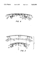
- FIG. 3 is a cross section of a heat exchange module of the present invention prior to installation.
- FIG. 4 is a cross section of a heat exchange module of the present invention as installed.
- FIG. 5 is a schematic illustration of a heat exchange system employing multiple heat exchange modules.
- Modules 10 are mounted between stringers 24 and beltframe members 26 which comprise the forming members to which the exterior fuselage skin 22 is attached.
- liquid heated coolant enters heat exchange module 10 through an inlet manifold 12, passes through heat exchange tube 14, and exits the module through outlet manifold 16.
- the heat exchange tube 14 is typically fabricated from aluminum, copper, steel, brass or alloys thereof and may be cylindrical in cross section or may have flattened sides due to heat transfer considerations.
- heat exchange tube 14 will be arranged in a number of tube passes as determined by the desired level of heat transfer, available space and other considerations.
- the tube passes may be parallel in which case each tube pass turns 180° or alternatively the tube passes may turn less than 180° to provide a continuously downsloping path to aid in draining the heat exchange tube and to facilitate thermosyphon action.
- Heat from the coolant is transferred through heat exchange tube 14 to spreader plate 20, having an arcuate or curved planar geometry, which is preferably formed from a resilient material having high thermal conductivity such as copper, aluminum or a composite material formed from pitch based carbon fibers such as those available from Amoco Performance Products, Ridgefield, Conn. under the trade designation P120 and P130.
- the pitch based carbon fiber composite material is preferred in many applications where weight is an important consideration. Since the spreader plate 20 is formed from a material having a high thermal conductivity, the heat load absorbed from heat exchange tube 14 is spread over areas of the spreader plate between passes of the heat exchange tube 14.
- the tube is fastened to the spreader plate through the use of conventional methods such as brazing, welding, clamping or with a contact or thermal cement.
- the spreader plate 20 is mounted against fuselage skin 22, which forms an arcuate or curved planar heat sink, permitting heat from the spreader plate 20 to be transferred to the aircraft's fuselage skin 22 where it is dissipated to the ambient environment.
- the fuselage skin serves as a heat sink for the heat exchange system.
- the heat exchange module 10 is mounted between stringers 24 and beltframe members 26.
- Stringers 24 and beltframe members 26 comprise the forming members to which the exterior fuselage skin 22 of a typical semimonocoque aircraft is attached.
- the heat exchange module 10 is mounted between stringers 24 with brackets comprising spring type stringer clamps 28 and tube braces 30.
- stringer clamps 28 and tube braces 30 could be combined into a one piece mounting bracket.
- the use of spring type stringer clamps 28 and tube braces 30 to mount the heat exchange module 10 does not require drilling, cutting or welding of the stringers or fuselage thereby facilitating installation and avoiding the creation of stress points.
- the portion of the aircraft's fuselage skin 22 to which heat exchange module 10 is attached defines an arc having a radius of curvature R 1 .
- spreader plate 20 and heat exchange tube 14 are formed along an arc having a radius of curvature R 2 such that R 1 >R 2 .
- the spreader plate 20 and heat exchange tube 14 are pushed against the fuselage skin 22 along the arc defined by the fuselage skin creating a reactionary spring like force that thrusts the heat exchange module 10 against the fuselage skin 22 across the area of the spreader plate 20 to facilitate heat transfer from the spreader plate 20 to the fuselage skin. Additionally, in some applications, it may also be desirable to coat the surface of spreader plate 20 and/or the fuselage skin 22 with a contact or thermal cement prior to installation to reduce contact resistance.
- the thickness of the spreader plate 20 may vary with the thermal conductivity of the fuselage skin 22, operating temperature, tube spacing and other design parameters.
- Liquid coolants suitable for use in connection with the present invention include water, ethylene glycol/water, Coolanols, Poly Alpha Olanol or cooling slurries (microencapsulated phase change materials in coolant fluids). Liquid coolant is circulated through the heat exchange module 10 with a pump, or alteratively, thermosyphon action may be used to circulate the coolant.
- Pump 50 circulates heated liquid coolant through inlet manifold 12 to individual heat exchange modules 10.
- Inlet and outlet valves 52 and 54 allow individual modules to be isolated from the system while bypass valves 56 allow for the modules to be connected in series or in parallel as desired.
- Liquid coolant exiting the modules is recirculated via return line 58 to cool electronics module 60.
- Other piping and valving arrangements may be used to interconnect individual modules depending upon the particular application and design requirements.
- the heat exchange system of the present invention because of its modular design, enables rapid and inexpensive installation of moderately sized liquid cooling systems for liquid cooled on board aircraft electronics.
- the modular design of the heat exchange system of the present invention also permits installation of an aircraft liquid cooling system consisting of multiple identical modules resulting in economies of high manufacturing quantities and commonality of parts.
- the modularity of the invention results in proportionality between the cooling capacity of a liquid cooling system and the installation cost of the system permitting earlier and experimental introduction of liquid cooled electronics and new liquid cooling fluids such as microencapsulated phase change materials.
- the heat exchange system of the present invention is installed with little or no structural modification permitting rapid and easy removal of the system subsequent to trial deployment of liquid cooled electronics.
- the modular design of the system also permits incremental upgrading of the system as the cooling demands increase. In the case of a failure, a single module can be isolated allowing the remainder of the system to operate. The failed module can then be scheduled for replacement at a convenient time whereas failure of existing systems may dictate that the aircraft be taken out of service immediately for extensive repairs.
Abstract
Description
Claims (13)
Priority Applications (3)
| Application Number | Priority Date | Filing Date | Title |
|---|---|---|---|
| US08/052,704 US5423498A (en) | 1993-04-27 | 1993-04-27 | Modular liquid skin heat exchanger |
| US08/421,262 US5667168A (en) | 1993-04-27 | 1995-04-13 | Modular liquid skin heat exchanger |
| US08/620,992 US5702073A (en) | 1993-04-27 | 1996-03-22 | Modular liquid skin heat exchanger |
Applications Claiming Priority (1)
| Application Number | Priority Date | Filing Date | Title |
|---|---|---|---|
| US08/052,704 US5423498A (en) | 1993-04-27 | 1993-04-27 | Modular liquid skin heat exchanger |
Related Child Applications (1)
| Application Number | Title | Priority Date | Filing Date |
|---|---|---|---|
| US08/421,262 Continuation US5667168A (en) | 1993-04-27 | 1995-04-13 | Modular liquid skin heat exchanger |
Publications (1)
| Publication Number | Publication Date |
|---|---|
| US5423498A true US5423498A (en) | 1995-06-13 |
Family
ID=21979355
Family Applications (3)
| Application Number | Title | Priority Date | Filing Date |
|---|---|---|---|
| US08/052,704 Expired - Lifetime US5423498A (en) | 1993-04-27 | 1993-04-27 | Modular liquid skin heat exchanger |
| US08/421,262 Expired - Fee Related US5667168A (en) | 1993-04-27 | 1995-04-13 | Modular liquid skin heat exchanger |
| US08/620,992 Expired - Lifetime US5702073A (en) | 1993-04-27 | 1996-03-22 | Modular liquid skin heat exchanger |
Family Applications After (2)
| Application Number | Title | Priority Date | Filing Date |
|---|---|---|---|
| US08/421,262 Expired - Fee Related US5667168A (en) | 1993-04-27 | 1995-04-13 | Modular liquid skin heat exchanger |
| US08/620,992 Expired - Lifetime US5702073A (en) | 1993-04-27 | 1996-03-22 | Modular liquid skin heat exchanger |
Country Status (1)
| Country | Link |
|---|---|
| US (3) | US5423498A (en) |
Cited By (28)
| Publication number | Priority date | Publication date | Assignee | Title |
|---|---|---|---|---|
| US5702073A (en) * | 1993-04-27 | 1997-12-30 | E-Systems, Inc. | Modular liquid skin heat exchanger |
| US5746064A (en) * | 1996-01-16 | 1998-05-05 | Borst, Inc. | Electrochemical heat exchanger |
| US5950710A (en) * | 1997-11-21 | 1999-09-14 | Continocean Tech Inc. | Overheat regulating system for vehicle passenger compartment |
| US6059017A (en) * | 1998-04-20 | 2000-05-09 | The United States Of America As Represented By The Secretary Of The Navy | Directional heat exchanger |
| US6131646A (en) * | 1998-01-19 | 2000-10-17 | Trw Inc. | Heat conductive interface material |
| US6398165B1 (en) * | 2000-11-02 | 2002-06-04 | The United States Of America As Represented By The Secretary Of The Navy | Protective enclosure with peripheral fluid storage facility |
| US20030141043A1 (en) * | 2002-01-29 | 2003-07-31 | Warburton Robert E. | Heat exchanger panel |
| US20030188856A1 (en) * | 2002-04-09 | 2003-10-09 | Roger Pays | High temperature heat exchanger structure |
| US20040159118A1 (en) * | 2003-02-19 | 2004-08-19 | The Boeing Company | System and method of refrigerating at least one enclosure |
| US20040159119A1 (en) * | 2003-02-19 | 2004-08-19 | The Boeing Company | System and method of refrigerating at least one enclosure |
| US20050034477A1 (en) * | 2003-08-15 | 2005-02-17 | The Boeing Company | System, apparatus, and method for passive and active refrigeration of at least one enclosure |
| US20080289801A1 (en) * | 2007-05-02 | 2008-11-27 | Batty J Clair | Modular Thermal Management System for Spacecraft |
| US20100277867A1 (en) * | 2009-04-29 | 2010-11-04 | Raytheon Company | Thermal Dissipation Mechanism for an Antenna |
| US20110024561A1 (en) * | 2006-08-22 | 2011-02-03 | Airbus Deutschland Gmbh | Frame element, aircraft air-conditioning system and method for the installation of a frame element in an aircraft |
| US20120175464A1 (en) * | 2008-12-17 | 2012-07-12 | Airbus Operations Gmbh | Pre-installed adaptable supply network for aeroplanes |
| US20130048243A1 (en) * | 2011-08-26 | 2013-02-28 | Hs Marston Aerospace Ltd. | Heat exhanger apparatus |
| US20130331019A1 (en) * | 2010-11-16 | 2013-12-12 | Airbus Operations Gmbh | Aircraft outer skin heat exchanger, aircraft cooling system and method for operating an aircraft outer skin heat exchanger |
| US20140305481A1 (en) * | 2013-04-12 | 2014-10-16 | Delphi Technologies, Inc. | Thermoelectric generator to engine exhaust manifold assembly |
| US20150068703A1 (en) * | 2013-09-06 | 2015-03-12 | Ge Aviation Systems Llc | Thermal management system and method of assembling the same |
| US20150191238A1 (en) * | 2012-06-29 | 2015-07-09 | Bae Systems Plc | Integrated heat exchanger |
| CN105416591A (en) * | 2015-12-11 | 2016-03-23 | 中国航空工业集团公司西安飞机设计研究所 | Double-layer airplane skin heat exchanger |
| US9986822B2 (en) | 2014-05-01 | 2018-06-05 | The Boeing Company | Method and apparatus for cooling an airline galley cart using a skin heat exchanger |
| US10222144B2 (en) | 2014-09-23 | 2019-03-05 | The Boeing Company | Methods and apparatus for a microtruss heat exchanger |
| US10507935B1 (en) * | 2018-05-02 | 2019-12-17 | Northrop Grumman Systems Corporation | Orthogonal shear structure |
| CN110988114A (en) * | 2019-12-13 | 2020-04-10 | 安徽九陆生物科技有限公司 | Detection apparatus suitable for liquid way |
| US20220357056A1 (en) * | 2019-03-26 | 2022-11-10 | Johnson Controls Tyco IP Holdings LLP | Auxiliary heat exchanger for hvac system |
| US11673682B2 (en) * | 2019-07-29 | 2023-06-13 | General Electric Company | Vehicle heat exchanger system including an inflatable member operable to press a cooling tube |
| US11713126B2 (en) * | 2019-08-12 | 2023-08-01 | The Boeing Company | Aircraft air conditioning pack assembly and method of assembling |
Families Citing this family (80)
| Publication number | Priority date | Publication date | Assignee | Title |
|---|---|---|---|---|
| DE19542843C1 (en) * | 1995-11-17 | 1996-12-19 | Daimler Benz Aerospace Airbus | Reduction of structure heating in supersonic aircraft during flight |
| US6251970B1 (en) * | 1996-10-25 | 2001-06-26 | Northrop Grumman Corporation | Heat absorbing surface coating |
| US6318852B1 (en) | 1998-12-30 | 2001-11-20 | Xerox Corporation | Color gamut extension of an ink composition |
| JP3644845B2 (en) * | 1999-04-28 | 2005-05-11 | 共和真空技術株式会社 | High-efficiency steam condenser in vacuum equipment. |
| US6658881B1 (en) * | 2000-11-17 | 2003-12-09 | Wesley M. Plattner | Apparatus and method for mounting a condenser in an aircraft |
| US8584738B2 (en) * | 2002-06-14 | 2013-11-19 | Lockheed Martin Corporation | Apparatus and method for extracting heat from a device |
| US7325772B1 (en) | 2003-09-04 | 2008-02-05 | L-3 Communications Corporation | Aircraft heat sink and electronics enclosure |
| US6942183B2 (en) * | 2003-09-22 | 2005-09-13 | Hamilton Sundstrand | Air cycle air conditioning with adaptive ram heat exchanger |
| DE10361392B4 (en) * | 2003-12-29 | 2009-07-30 | Airbus Deutschland Gmbh | Air distribution system |
| DE10361686B4 (en) * | 2003-12-30 | 2008-04-24 | Airbus Deutschland Gmbh | Cooling system for cooling heat generating equipment in an aircraft |
| DE10361653B4 (en) * | 2003-12-30 | 2008-08-07 | Airbus Deutschland Gmbh | Cooling device for removing heat from an arranged in the interior of an aircraft heat source |
| GR1004729B (en) * | 2004-01-02 | 2004-11-22 | Κωνσταντινος Σπυριδωνα Τραβασαρος | Heating body with copper water pipe structure welded to aluminium sheets by means of laser beam bundle |
| DE202005012048U1 (en) * | 2005-07-22 | 2006-12-07 | Liebherr-Hausgeräte Ochsenhausen GmbH | Pipe / plate liquefier for refrigerators and / or freezers |
| FR2894563B1 (en) * | 2005-12-14 | 2009-06-05 | Liebherr Aerospace Toulouse Sa | CIRCUIT AND METHOD FOR REALIZING THERMAL EXCHANGES THROUGH A COOLANT FLUID IN AN AIRCRAFT ENVIRONMENTAL CONTROL SYSTEM. |
| US20070140050A1 (en) * | 2005-12-19 | 2007-06-21 | Dave Humphrey Enterprises, Inc. | Concrete slurry tank |
| DE102006041788B4 (en) * | 2006-09-06 | 2012-06-14 | Airbus Operations Gmbh | An aircraft electronics cooling device for an aircraft with a liquid cooling system |
| US8950468B2 (en) * | 2007-05-11 | 2015-02-10 | The Boeing Company | Cooling system for aerospace vehicle components |
| DE102007049926A1 (en) * | 2007-10-18 | 2009-04-23 | Airbus Deutschland Gmbh | System and method for air conditioning at least a portion of an aircraft |
| EP2072763B1 (en) * | 2007-12-21 | 2015-04-08 | Techspace Aero S.A. | Heat exchange system in a turbomachine |
| DE102008025951B4 (en) * | 2008-05-30 | 2010-10-28 | Airbus Deutschland Gmbh | Cooling an electronic device in an aircraft by a case-wise single-phase or two-phase cooling |
| DE102008026536A1 (en) * | 2008-06-03 | 2009-12-17 | Airbus Deutschland Gmbh | System and method for cooling a heat-fogged device in a vehicle, in particular an aircraft |
| GB2474923B (en) | 2008-07-18 | 2011-11-16 | Phasor Solutions Ltd | A phased array antenna and a method of operating a phased array antenna |
| DE102008035823A1 (en) * | 2008-07-31 | 2010-02-25 | Airbus Deutschland Gmbh | Heat exchanger for the outer skin of an aircraft |
| US20100084118A1 (en) * | 2008-08-21 | 2010-04-08 | Airbus Operations | Cooling system for aircraft electric or electronic devices |
| DE102008044645B3 (en) * | 2008-08-27 | 2010-02-18 | Airbus Deutschland Gmbh | An aircraft signal computer system comprising a plurality of modular signal processor units |
| US9238398B2 (en) * | 2008-09-25 | 2016-01-19 | B/E Aerospace, Inc. | Refrigeration systems and methods for connection with a vehicle's liquid cooling system |
| US20100326049A1 (en) * | 2009-06-25 | 2010-12-30 | Honeywell International Inc. | Cooling systems for rotorcraft engines |
| US20110073274A1 (en) * | 2009-09-30 | 2011-03-31 | Ics Group Inc. | Modular climate change tarp system |
| US8496201B2 (en) * | 2010-01-11 | 2013-07-30 | Lockheed Martin Corporation | High capacity heat sink |
| US8961891B2 (en) | 2010-08-20 | 2015-02-24 | Lockheed Martin Corporation | Catalytic alcohol dehydrogenation heat sink for mobile application |
| DE102010047970A1 (en) * | 2010-10-08 | 2012-04-12 | Airbus Operations Gmbh | Airconditioned air conditioning with conditioned heat sink |
| US8967531B2 (en) | 2011-03-28 | 2015-03-03 | Rolls-Royce Corporation | Aircraft and airborne electrical power and thermal management system |
| WO2012135314A1 (en) | 2011-03-29 | 2012-10-04 | Rolls-Royce North American Technologies Inc. | Vehicle system |
| EP2834149A1 (en) * | 2012-04-05 | 2015-02-11 | Airbus Operations GmbH | Craft outer skin heat exchanger and method for manufacturing a craft outer skin heat exchanger |
| GB201215114D0 (en) | 2012-08-24 | 2012-10-10 | Phasor Solutions Ltd | Improvements in or relating to the processing of noisy analogue signals |
| US9527261B1 (en) | 2012-09-14 | 2016-12-27 | Hrl Laboratories, Llc | Hollow polymer micro-truss structures containing pressurized fluids |
| FR2995589B1 (en) * | 2012-09-19 | 2015-07-31 | Liebherr Aerospace Toulouse Sas | BODY PANEL FOR A TRANSPORT VEHICLE COMPRISING A THERMAL EXCHANGE DEVICE AND A TRANSPORT VEHICLE COMPRISING SUCH A BODY PANEL |
| US20140251585A1 (en) * | 2013-03-05 | 2014-09-11 | The Boeing Company | Micro-lattice Cross-flow Heat Exchangers for Aircraft |
| FR3017936B1 (en) * | 2014-02-21 | 2019-03-15 | Thales | THERMAL CONTROL SYSTEM OF AT LEAST ONE ELECTRONIC MODULE ON BOARD AN AIRCRAFT |
| GB201403507D0 (en) | 2014-02-27 | 2014-04-16 | Phasor Solutions Ltd | Apparatus comprising an antenna array |
| US10364043B2 (en) * | 2014-07-02 | 2019-07-30 | Embraer S.A. | Passive aircraft cooling systems and methods |
| US10059435B2 (en) * | 2014-12-04 | 2018-08-28 | Parker-Hannifin Corporation | Low drag skin heat exchanger |
| US10823066B2 (en) | 2015-12-09 | 2020-11-03 | General Electric Company | Thermal management system |
| US10443436B2 (en) | 2016-07-01 | 2019-10-15 | General Electric Company | Modular annular heat exchanger |
| US11187156B2 (en) | 2017-11-21 | 2021-11-30 | General Electric Company | Thermal management system |
| US11125165B2 (en) | 2017-11-21 | 2021-09-21 | General Electric Company | Thermal management system |
| US11022037B2 (en) | 2018-01-04 | 2021-06-01 | General Electric Company | Gas turbine engine thermal management system |
| US10941706B2 (en) | 2018-02-13 | 2021-03-09 | General Electric Company | Closed cycle heat engine for a gas turbine engine |
| US11143104B2 (en) | 2018-02-20 | 2021-10-12 | General Electric Company | Thermal management system |
| US11174789B2 (en) | 2018-05-23 | 2021-11-16 | General Electric Company | Air cycle assembly for a gas turbine engine assembly |
| US11186382B2 (en) | 2018-11-02 | 2021-11-30 | General Electric Company | Fuel oxygen conversion unit |
| US11148824B2 (en) | 2018-11-02 | 2021-10-19 | General Electric Company | Fuel delivery system having a fuel oxygen reduction unit |
| US11447263B2 (en) | 2018-11-02 | 2022-09-20 | General Electric Company | Fuel oxygen reduction unit control system |
| US11319085B2 (en) | 2018-11-02 | 2022-05-03 | General Electric Company | Fuel oxygen conversion unit with valve control |
| US11851204B2 (en) | 2018-11-02 | 2023-12-26 | General Electric Company | Fuel oxygen conversion unit with a dual separator pump |
| US11131256B2 (en) | 2018-11-02 | 2021-09-28 | General Electric Company | Fuel oxygen conversion unit with a fuel/gas separator |
| US11420763B2 (en) | 2018-11-02 | 2022-08-23 | General Electric Company | Fuel delivery system having a fuel oxygen reduction unit |
| US11193671B2 (en) | 2018-11-02 | 2021-12-07 | General Electric Company | Fuel oxygen conversion unit with a fuel gas separator |
| US11577852B2 (en) | 2018-11-02 | 2023-02-14 | General Electric Company | Fuel oxygen conversion unit |
| US11085636B2 (en) | 2018-11-02 | 2021-08-10 | General Electric Company | Fuel oxygen conversion unit |
| US11161622B2 (en) | 2018-11-02 | 2021-11-02 | General Electric Company | Fuel oxygen reduction unit |
| US11391211B2 (en) | 2018-11-28 | 2022-07-19 | General Electric Company | Waste heat recovery system |
| US11015534B2 (en) | 2018-11-28 | 2021-05-25 | General Electric Company | Thermal management system |
| JP7251975B2 (en) | 2018-12-27 | 2023-04-04 | 川崎重工業株式会社 | Skin cooling system |
| JP2020106207A (en) * | 2018-12-27 | 2020-07-09 | 川崎重工業株式会社 | Loop-type heat pipe and transporter |
| JP7205969B2 (en) * | 2018-12-27 | 2023-01-17 | 川崎重工業株式会社 | Skin cooling system |
| US10914274B1 (en) | 2019-09-11 | 2021-02-09 | General Electric Company | Fuel oxygen reduction unit with plasma reactor |
| US11774427B2 (en) | 2019-11-27 | 2023-10-03 | General Electric Company | Methods and apparatus for monitoring health of fuel oxygen conversion unit |
| US11765871B2 (en) | 2020-03-26 | 2023-09-19 | Ge Aviation Systems Llc | Aircraft and method for thermal management |
| US11866182B2 (en) | 2020-05-01 | 2024-01-09 | General Electric Company | Fuel delivery system having a fuel oxygen reduction unit |
| US11906163B2 (en) | 2020-05-01 | 2024-02-20 | General Electric Company | Fuel oxygen conversion unit with integrated water removal |
| US11773776B2 (en) | 2020-05-01 | 2023-10-03 | General Electric Company | Fuel oxygen reduction unit for prescribed operating conditions |
| US11434824B2 (en) | 2021-02-03 | 2022-09-06 | General Electric Company | Fuel heater and energy conversion system |
| US11591965B2 (en) | 2021-03-29 | 2023-02-28 | General Electric Company | Thermal management system for transferring heat between fluids |
| US20220410246A1 (en) * | 2021-06-25 | 2022-12-29 | Ultracell Llc | Fuselage heat exchanger for cooling power source for unmanned aerial vehicles (uavs) |
| US11674396B2 (en) | 2021-07-30 | 2023-06-13 | General Electric Company | Cooling air delivery assembly |
| US11920500B2 (en) | 2021-08-30 | 2024-03-05 | General Electric Company | Passive flow modulation device |
| US11542870B1 (en) | 2021-11-24 | 2023-01-03 | General Electric Company | Gas supply system |
| CN114435582A (en) * | 2022-01-10 | 2022-05-06 | 南京理工大学 | Nearby-exhausting aircraft skin cooling system based on wind-liquid comprehensive cooling structure |
| US11692448B1 (en) | 2022-03-04 | 2023-07-04 | General Electric Company | Passive valve assembly for a nozzle of a gas turbine engine |
Citations (14)
| Publication number | Priority date | Publication date | Assignee | Title |
|---|---|---|---|---|
| US2646971A (en) * | 1950-06-17 | 1953-07-28 | Raskin Walter | Heat exchange unit |
| US2856163A (en) * | 1954-04-15 | 1958-10-14 | Illinois Mcgraw Electric Compa | Refrigerator condenser |
| US3776305A (en) * | 1972-02-22 | 1973-12-04 | United Aircraft Prod | Heat transfer system |
| US4057104A (en) * | 1976-08-26 | 1977-11-08 | Westinghouse Electric Corporation | Temperature controlled airborne electronic assembly |
| US4273183A (en) * | 1979-07-31 | 1981-06-16 | The United States Of America As Represented By The Secretary Of The Air Force | Mechanical heat transfer device |
| US4557319A (en) * | 1982-07-02 | 1985-12-10 | Arnold Alanson J | Marine keel cooler |
| US4763727A (en) * | 1985-12-10 | 1988-08-16 | Suddeutsche Kuhlerfabrik Julius Fr. Behr Gmbh & Co. Kg | Panel heat exchanger |
| US4786015A (en) * | 1986-12-31 | 1988-11-22 | Sundstrand Corporation | Structural cooling unit |
| US4819720A (en) * | 1984-11-09 | 1989-04-11 | Mcdonnell Douglas Corporation | Skin heat exchanger |
| US4871012A (en) * | 1986-09-12 | 1989-10-03 | Ford Aerospace Corporation | Variable conductance thermal insulation blanket |
| US4969509A (en) * | 1988-04-16 | 1990-11-13 | Deutsche Lufthansa Aktiengesellschaft | Airplane |
| JPH0325096A (en) * | 1989-06-23 | 1991-02-01 | S T S Kk | Cooling device utilizing airframe outer surface cooler for aviation electronic equipment |
| US5131458A (en) * | 1991-03-25 | 1992-07-21 | Davis Energy Group, Inc. | Modular back side radiant heating panels with spring retention devices |
| US5158133A (en) * | 1991-02-14 | 1992-10-27 | Erno Raumfahrttechnik Gmbh | Evaporation heat exchanger, especially for a spacecraft |
Family Cites Families (9)
| Publication number | Priority date | Publication date | Assignee | Title |
|---|---|---|---|---|
| US2330632A (en) * | 1940-10-12 | 1943-09-28 | Seligman Roger Adolphe Leonard | Means of radiating heat |
| US3977206A (en) * | 1972-02-22 | 1976-08-31 | United Aircraft Products, Inc. | Heat transfer system |
| US4098261A (en) * | 1977-02-23 | 1978-07-04 | Richard Edwin Watt | Flat plate solar collector panel having extruded thermal conductors |
| US4687048A (en) * | 1986-06-18 | 1987-08-18 | The United States Of America As Represented By The Administrator Of The National Aeronautics And Space Administration | Monogroove cold plate |
| US4991797A (en) * | 1989-01-17 | 1991-02-12 | Northrop Corporation | Infrared signature reduction of aerodynamic surfaces |
| JPH0326096A (en) * | 1989-06-22 | 1991-02-04 | Fujitsu Ltd | Cpu resetting system for controller to be supervised |
| US5526873A (en) * | 1989-07-19 | 1996-06-18 | Valeo Thermique Moteur | Heat exchanger apparatus for a plurality of cooling circuits using the same coolant |
| US5000256A (en) * | 1990-07-20 | 1991-03-19 | Minnesota Mining And Manufacturing Company | Heat transfer bag with thermal via |
| US5423498A (en) * | 1993-04-27 | 1995-06-13 | E-Systems, Inc. | Modular liquid skin heat exchanger |
-
1993
- 1993-04-27 US US08/052,704 patent/US5423498A/en not_active Expired - Lifetime
-
1995
- 1995-04-13 US US08/421,262 patent/US5667168A/en not_active Expired - Fee Related
-
1996
- 1996-03-22 US US08/620,992 patent/US5702073A/en not_active Expired - Lifetime
Patent Citations (14)
| Publication number | Priority date | Publication date | Assignee | Title |
|---|---|---|---|---|
| US2646971A (en) * | 1950-06-17 | 1953-07-28 | Raskin Walter | Heat exchange unit |
| US2856163A (en) * | 1954-04-15 | 1958-10-14 | Illinois Mcgraw Electric Compa | Refrigerator condenser |
| US3776305A (en) * | 1972-02-22 | 1973-12-04 | United Aircraft Prod | Heat transfer system |
| US4057104A (en) * | 1976-08-26 | 1977-11-08 | Westinghouse Electric Corporation | Temperature controlled airborne electronic assembly |
| US4273183A (en) * | 1979-07-31 | 1981-06-16 | The United States Of America As Represented By The Secretary Of The Air Force | Mechanical heat transfer device |
| US4557319A (en) * | 1982-07-02 | 1985-12-10 | Arnold Alanson J | Marine keel cooler |
| US4819720A (en) * | 1984-11-09 | 1989-04-11 | Mcdonnell Douglas Corporation | Skin heat exchanger |
| US4763727A (en) * | 1985-12-10 | 1988-08-16 | Suddeutsche Kuhlerfabrik Julius Fr. Behr Gmbh & Co. Kg | Panel heat exchanger |
| US4871012A (en) * | 1986-09-12 | 1989-10-03 | Ford Aerospace Corporation | Variable conductance thermal insulation blanket |
| US4786015A (en) * | 1986-12-31 | 1988-11-22 | Sundstrand Corporation | Structural cooling unit |
| US4969509A (en) * | 1988-04-16 | 1990-11-13 | Deutsche Lufthansa Aktiengesellschaft | Airplane |
| JPH0325096A (en) * | 1989-06-23 | 1991-02-01 | S T S Kk | Cooling device utilizing airframe outer surface cooler for aviation electronic equipment |
| US5158133A (en) * | 1991-02-14 | 1992-10-27 | Erno Raumfahrttechnik Gmbh | Evaporation heat exchanger, especially for a spacecraft |
| US5131458A (en) * | 1991-03-25 | 1992-07-21 | Davis Energy Group, Inc. | Modular back side radiant heating panels with spring retention devices |
Cited By (41)
| Publication number | Priority date | Publication date | Assignee | Title |
|---|---|---|---|---|
| US5702073A (en) * | 1993-04-27 | 1997-12-30 | E-Systems, Inc. | Modular liquid skin heat exchanger |
| US5746064A (en) * | 1996-01-16 | 1998-05-05 | Borst, Inc. | Electrochemical heat exchanger |
| US5768906A (en) * | 1996-01-16 | 1998-06-23 | Borst, Inc. | Electrochemical heat exchanger |
| US5950710A (en) * | 1997-11-21 | 1999-09-14 | Continocean Tech Inc. | Overheat regulating system for vehicle passenger compartment |
| US6131646A (en) * | 1998-01-19 | 2000-10-17 | Trw Inc. | Heat conductive interface material |
| US6059017A (en) * | 1998-04-20 | 2000-05-09 | The United States Of America As Represented By The Secretary Of The Navy | Directional heat exchanger |
| US6398165B1 (en) * | 2000-11-02 | 2002-06-04 | The United States Of America As Represented By The Secretary Of The Navy | Protective enclosure with peripheral fluid storage facility |
| US6907920B2 (en) * | 2002-01-29 | 2005-06-21 | United Technologies Corporation | Heat exchanger panel |
| US20030141043A1 (en) * | 2002-01-29 | 2003-07-31 | Warburton Robert E. | Heat exchanger panel |
| FR2835313A1 (en) * | 2002-01-29 | 2003-08-01 | United Technologies Corp | HEAT EXCHANGER PANEL |
| US20030188856A1 (en) * | 2002-04-09 | 2003-10-09 | Roger Pays | High temperature heat exchanger structure |
| US20040159118A1 (en) * | 2003-02-19 | 2004-08-19 | The Boeing Company | System and method of refrigerating at least one enclosure |
| US20040159119A1 (en) * | 2003-02-19 | 2004-08-19 | The Boeing Company | System and method of refrigerating at least one enclosure |
| US7089756B2 (en) | 2003-02-19 | 2006-08-15 | The Boeing Company | System and method of refrigerating at least one enclosure |
| US7093458B2 (en) | 2003-02-19 | 2006-08-22 | The Boeing Company | System and method of refrigerating at least one enclosure |
| US20050034477A1 (en) * | 2003-08-15 | 2005-02-17 | The Boeing Company | System, apparatus, and method for passive and active refrigeration of at least one enclosure |
| US7007501B2 (en) | 2003-08-15 | 2006-03-07 | The Boeing Company | System, apparatus, and method for passive and active refrigeration of at least one enclosure |
| US20110024561A1 (en) * | 2006-08-22 | 2011-02-03 | Airbus Deutschland Gmbh | Frame element, aircraft air-conditioning system and method for the installation of a frame element in an aircraft |
| US8262023B2 (en) * | 2006-08-22 | 2012-09-11 | Airbus Operation GmbH | Aircraft frame element connected to an air-conditioning system |
| US20080289801A1 (en) * | 2007-05-02 | 2008-11-27 | Batty J Clair | Modular Thermal Management System for Spacecraft |
| US8616501B2 (en) * | 2008-12-17 | 2013-12-31 | Airbus Operations Gmbh | Pre-installed adaptable supply network for aeroplanes |
| US20120175464A1 (en) * | 2008-12-17 | 2012-07-12 | Airbus Operations Gmbh | Pre-installed adaptable supply network for aeroplanes |
| US8045329B2 (en) | 2009-04-29 | 2011-10-25 | Raytheon Company | Thermal dissipation mechanism for an antenna |
| US20100277867A1 (en) * | 2009-04-29 | 2010-11-04 | Raytheon Company | Thermal Dissipation Mechanism for an Antenna |
| US20130331019A1 (en) * | 2010-11-16 | 2013-12-12 | Airbus Operations Gmbh | Aircraft outer skin heat exchanger, aircraft cooling system and method for operating an aircraft outer skin heat exchanger |
| US10011362B2 (en) * | 2010-11-16 | 2018-07-03 | Airbus Operations Gmbh | Aircraft outer skin heat exchanger, aircraft cooling system and method for operating an aircraft outer skin heat exchanger |
| US20130048243A1 (en) * | 2011-08-26 | 2013-02-28 | Hs Marston Aerospace Ltd. | Heat exhanger apparatus |
| US9260191B2 (en) * | 2011-08-26 | 2016-02-16 | Hs Marston Aerospace Ltd. | Heat exhanger apparatus including heat transfer surfaces |
| US20150191238A1 (en) * | 2012-06-29 | 2015-07-09 | Bae Systems Plc | Integrated heat exchanger |
| US20140305481A1 (en) * | 2013-04-12 | 2014-10-16 | Delphi Technologies, Inc. | Thermoelectric generator to engine exhaust manifold assembly |
| US20150068703A1 (en) * | 2013-09-06 | 2015-03-12 | Ge Aviation Systems Llc | Thermal management system and method of assembling the same |
| US9986822B2 (en) | 2014-05-01 | 2018-06-05 | The Boeing Company | Method and apparatus for cooling an airline galley cart using a skin heat exchanger |
| US10222144B2 (en) | 2014-09-23 | 2019-03-05 | The Boeing Company | Methods and apparatus for a microtruss heat exchanger |
| CN105416591A (en) * | 2015-12-11 | 2016-03-23 | 中国航空工业集团公司西安飞机设计研究所 | Double-layer airplane skin heat exchanger |
| US10507935B1 (en) * | 2018-05-02 | 2019-12-17 | Northrop Grumman Systems Corporation | Orthogonal shear structure |
| US20220357056A1 (en) * | 2019-03-26 | 2022-11-10 | Johnson Controls Tyco IP Holdings LLP | Auxiliary heat exchanger for hvac system |
| US11852372B2 (en) * | 2019-03-26 | 2023-12-26 | Johnson Controls Tyco IP Holdings LLP | Auxiliary heat exchanger for HVAC system |
| US11673682B2 (en) * | 2019-07-29 | 2023-06-13 | General Electric Company | Vehicle heat exchanger system including an inflatable member operable to press a cooling tube |
| US11713126B2 (en) * | 2019-08-12 | 2023-08-01 | The Boeing Company | Aircraft air conditioning pack assembly and method of assembling |
| CN110988114A (en) * | 2019-12-13 | 2020-04-10 | 安徽九陆生物科技有限公司 | Detection apparatus suitable for liquid way |
| CN110988114B (en) * | 2019-12-13 | 2022-05-13 | 安徽九陆生物科技有限公司 | Detection apparatus suitable for liquid way |
Also Published As
| Publication number | Publication date |
|---|---|
| US5667168A (en) | 1997-09-16 |
| US5702073A (en) | 1997-12-30 |
Similar Documents
| Publication | Publication Date | Title |
|---|---|---|
| US5423498A (en) | Modular liquid skin heat exchanger | |
| US7213391B2 (en) | Cooling systems | |
| US10011362B2 (en) | Aircraft outer skin heat exchanger, aircraft cooling system and method for operating an aircraft outer skin heat exchanger | |
| US4404793A (en) | Apparatus for improving the fuel efficiency of a gas turbine engine | |
| JP3320069B2 (en) | Gas turbine engine exhaust gas deicing system | |
| EP1380799A2 (en) | Method and apparatus for cooling with coolant at a subambient pressure | |
| US20050195570A1 (en) | Low momentum loss fluid manifold system | |
| US8127829B2 (en) | Metal foam heat exchanger | |
| US11673682B2 (en) | Vehicle heat exchanger system including an inflatable member operable to press a cooling tube | |
| US10364043B2 (en) | Passive aircraft cooling systems and methods | |
| US5267605A (en) | Microtube array space radiator | |
| US20160120065A1 (en) | Manifold for a cooling system | |
| GB2437383A (en) | Hybrid ceramic core cold plate | |
| US20150192368A1 (en) | Method of condensing vapor in two-phase flow within a cooling apparatus | |
| US20130255917A1 (en) | Semiconductor cooling apparatus | |
| US10488117B1 (en) | Aircraft heat exchanger defrost system | |
| US20230194185A1 (en) | Evolutive precooler | |
| WO2008008324A2 (en) | Galley cooling heat sink through water system | |
| Phillips et al. | Loop heat pipe anti icing system development program summary | |
| Tongue et al. | ISS active thermal control system (ATCS) heat exchangers and cold plates | |
| US11859921B1 (en) | Microtube heat exchanger | |
| Fritz | Advanced spacecraft thermal control techniques | |
| Leimkuehler et al. | Development of a contaminant insensitive sublimator | |
| US20230389425A1 (en) | Method and system for cooling of a device | |
| Brown et al. | Titanium cooling coils for surface ship applications |
Legal Events
| Date | Code | Title | Description |
|---|---|---|---|
| AS | Assignment |
Owner name: E-SYSTEMS, INC., TEXAS Free format text: ASSIGNMENT OF ASSIGNORS INTEREST;ASSIGNOR:FLUEGEL, KYLE G.;REEL/FRAME:006564/0122 Effective date: 19930329 |
|
| STPP | Information on status: patent application and granting procedure in general |
Free format text: APPLICATION UNDERGOING PREEXAM PROCESSING |
|
| CC | Certificate of correction | ||
| AS | Assignment |
Owner name: RAYTHEON E-SYSTEMS, INC., A CORP. OF DELAWARE, TEX Free format text: CHANGE OF NAME;ASSIGNOR:E-SYSTEMS, INC.;REEL/FRAME:009507/0603 Effective date: 19960703 |
|
| AS | Assignment |
Owner name: RAYTHEON COMPANY, A CORP. OF DELAWARE, MASSACHUSET Free format text: ASSIGNMENT OF ASSIGNORS INTEREST;ASSIGNOR:RAYTHEON E-SYSTEMS, INC., A CORP. OF DELAWARE;REEL/FRAME:009570/0001 Effective date: 19981030 |
|
| FPAY | Fee payment |
Year of fee payment: 4 |
|
| AS | Assignment |
Owner name: L-3 COMMUNICATIONS INTEGRATED SYSTEMS L.P., NEW YO Free format text: ASSIGNMENT OF ASSIGNORS INTEREST;ASSIGNOR:RAYTHEON COMPANY;REEL/FRAME:013067/0432 Effective date: 20020606 |
|
| FPAY | Fee payment |
Year of fee payment: 8 |
|
| REMI | Maintenance fee reminder mailed | ||
| FPAY | Fee payment |
Year of fee payment: 12 |