US7055219B2 - Hinge for portable terminal - Google Patents
Hinge for portable terminal Download PDFInfo
- Publication number
- US7055219B2 US7055219B2 US10/903,726 US90372604A US7055219B2 US 7055219 B2 US7055219 B2 US 7055219B2 US 90372604 A US90372604 A US 90372604A US 7055219 B2 US7055219 B2 US 7055219B2
- Authority
- US
- United States
- Prior art keywords
- casing
- hinge
- cam
- opening
- closing
- Prior art date
- Legal status (The legal status is an assumption and is not a legal conclusion. Google has not performed a legal analysis and makes no representation as to the accuracy of the status listed.)
- Expired - Fee Related, expires
Links
Images


Classifications
-
- H—ELECTRICITY
- H04—ELECTRIC COMMUNICATION TECHNIQUE
- H04B—TRANSMISSION
- H04B1/00—Details of transmission systems, not covered by a single one of groups H04B3/00 - H04B13/00; Details of transmission systems not characterised by the medium used for transmission
- H04B1/38—Transceivers, i.e. devices in which transmitter and receiver form a structural unit and in which at least one part is used for functions of transmitting and receiving
-
- H—ELECTRICITY
- H04—ELECTRIC COMMUNICATION TECHNIQUE
- H04M—TELEPHONIC COMMUNICATION
- H04M1/00—Substation equipment, e.g. for use by subscribers
- H04M1/02—Constructional features of telephone sets
- H04M1/0202—Portable telephone sets, e.g. cordless phones, mobile phones or bar type handsets
- H04M1/0206—Portable telephones comprising a plurality of mechanically joined movable body parts, e.g. hinged housings
- H04M1/0208—Portable telephones comprising a plurality of mechanically joined movable body parts, e.g. hinged housings characterized by the relative motions of the body parts
- H04M1/021—Portable telephones comprising a plurality of mechanically joined movable body parts, e.g. hinged housings characterized by the relative motions of the body parts using combined folding and rotation motions
- H04M1/0212—Portable telephones comprising a plurality of mechanically joined movable body parts, e.g. hinged housings characterized by the relative motions of the body parts using combined folding and rotation motions with a two degrees of freedom mechanism, i.e. folding around a first axis and rotating around a second axis perpendicular to the first
-
- G—PHYSICS
- G06—COMPUTING; CALCULATING OR COUNTING
- G06F—ELECTRIC DIGITAL DATA PROCESSING
- G06F1/00—Details not covered by groups G06F3/00 - G06F13/00 and G06F21/00
- G06F1/16—Constructional details or arrangements
- G06F1/1613—Constructional details or arrangements for portable computers
- G06F1/1615—Constructional details or arrangements for portable computers with several enclosures having relative motions, each enclosure supporting at least one I/O or computing function
- G06F1/1616—Constructional details or arrangements for portable computers with several enclosures having relative motions, each enclosure supporting at least one I/O or computing function with folding flat displays, e.g. laptop computers or notebooks having a clamshell configuration, with body parts pivoting to an open position around an axis parallel to the plane they define in closed position
-
- G—PHYSICS
- G06—COMPUTING; CALCULATING OR COUNTING
- G06F—ELECTRIC DIGITAL DATA PROCESSING
- G06F1/00—Details not covered by groups G06F3/00 - G06F13/00 and G06F21/00
- G06F1/16—Constructional details or arrangements
- G06F1/1613—Constructional details or arrangements for portable computers
- G06F1/1615—Constructional details or arrangements for portable computers with several enclosures having relative motions, each enclosure supporting at least one I/O or computing function
- G06F1/1622—Constructional details or arrangements for portable computers with several enclosures having relative motions, each enclosure supporting at least one I/O or computing function with enclosures rotating around an axis perpendicular to the plane they define or with ball-joint coupling, e.g. PDA with display enclosure orientation changeable between portrait and landscape by rotation with respect to a coplanar body enclosure
-
- G—PHYSICS
- G06—COMPUTING; CALCULATING OR COUNTING
- G06F—ELECTRIC DIGITAL DATA PROCESSING
- G06F1/00—Details not covered by groups G06F3/00 - G06F13/00 and G06F21/00
- G06F1/16—Constructional details or arrangements
- G06F1/1613—Constructional details or arrangements for portable computers
- G06F1/1633—Constructional details or arrangements of portable computers not specific to the type of enclosures covered by groups G06F1/1615 - G06F1/1626
- G06F1/1675—Miscellaneous details related to the relative movement between the different enclosures or enclosure parts
- G06F1/1679—Miscellaneous details related to the relative movement between the different enclosures or enclosure parts for locking or maintaining the movable parts of the enclosure in a fixed position, e.g. latching mechanism at the edge of the display in a laptop or for the screen protective cover of a PDA
-
- G—PHYSICS
- G06—COMPUTING; CALCULATING OR COUNTING
- G06F—ELECTRIC DIGITAL DATA PROCESSING
- G06F1/00—Details not covered by groups G06F3/00 - G06F13/00 and G06F21/00
- G06F1/16—Constructional details or arrangements
- G06F1/1613—Constructional details or arrangements for portable computers
- G06F1/1633—Constructional details or arrangements of portable computers not specific to the type of enclosures covered by groups G06F1/1615 - G06F1/1626
- G06F1/1675—Miscellaneous details related to the relative movement between the different enclosures or enclosure parts
- G06F1/1681—Details related solely to hinges
-
- E—FIXED CONSTRUCTIONS
- E05—LOCKS; KEYS; WINDOW OR DOOR FITTINGS; SAFES
- E05D—HINGES OR SUSPENSION DEVICES FOR DOORS, WINDOWS OR WINGS
- E05D11/00—Additional features or accessories of hinges
- E05D11/10—Devices for preventing movement between relatively-movable hinge parts
- E05D11/1007—Devices for preventing movement between relatively-movable hinge parts with positive locking
-
- E—FIXED CONSTRUCTIONS
- E05—LOCKS; KEYS; WINDOW OR DOOR FITTINGS; SAFES
- E05D—HINGES OR SUSPENSION DEVICES FOR DOORS, WINDOWS OR WINGS
- E05D11/00—Additional features or accessories of hinges
- E05D11/10—Devices for preventing movement between relatively-movable hinge parts
- E05D11/1028—Devices for preventing movement between relatively-movable hinge parts for maintaining the hinge in two or more positions, e.g. intermediate or fully open
- E05D11/1078—Devices for preventing movement between relatively-movable hinge parts for maintaining the hinge in two or more positions, e.g. intermediate or fully open the maintaining means acting parallel to the pivot
-
- E—FIXED CONSTRUCTIONS
- E05—LOCKS; KEYS; WINDOW OR DOOR FITTINGS; SAFES
- E05D—HINGES OR SUSPENSION DEVICES FOR DOORS, WINDOWS OR WINGS
- E05D3/00—Hinges with pins
- E05D3/06—Hinges with pins with two or more pins
- E05D3/10—Hinges with pins with two or more pins with non-parallel pins
-
- E—FIXED CONSTRUCTIONS
- E05—LOCKS; KEYS; WINDOW OR DOOR FITTINGS; SAFES
- E05Y—INDEXING SCHEME RELATING TO HINGES OR OTHER SUSPENSION DEVICES FOR DOORS, WINDOWS OR WINGS AND DEVICES FOR MOVING WINGS INTO OPEN OR CLOSED POSITION, CHECKS FOR WINGS AND WING FITTINGS NOT OTHERWISE PROVIDED FOR, CONCERNED WITH THE FUNCTIONING OF THE WING
- E05Y2900/00—Application of doors, windows, wings or fittings thereof
- E05Y2900/60—Application of doors, windows, wings or fittings thereof for other use
- E05Y2900/606—Application of doors, windows, wings or fittings thereof for other use for electronic devices
-
- Y—GENERAL TAGGING OF NEW TECHNOLOGICAL DEVELOPMENTS; GENERAL TAGGING OF CROSS-SECTIONAL TECHNOLOGIES SPANNING OVER SEVERAL SECTIONS OF THE IPC; TECHNICAL SUBJECTS COVERED BY FORMER USPC CROSS-REFERENCE ART COLLECTIONS [XRACs] AND DIGESTS
- Y10—TECHNICAL SUBJECTS COVERED BY FORMER USPC
- Y10S—TECHNICAL SUBJECTS COVERED BY FORMER USPC CROSS-REFERENCE ART COLLECTIONS [XRACs] AND DIGESTS
- Y10S248/00—Supports
- Y10S248/917—Video display screen support
- Y10S248/919—Adjustably orientable video screen support
Definitions
- the present invention relates to a hinge for portable terminal suitable for use in portable terminals such as a cellular phone, a PHS, and a small computer.
- a cellular phone, a PHS, and the like in particular, the following structure is becoming on the mainstream in order to realize, when not in use, the compact size, the protection of a keyboard portion and a display portion, and further, the prevention of the malfunction of the keyboard portion. That is, a first casing having the keyboard portion and a microphone thereon and a second casing having the display portion and a speaker thereon are foldable via a hinge, with the keyboard portion and the display portion facing each other.
- the display portion is formed to be vertically long so as to have a slim shape.
- the portable terminals are additionally equipped with various functions, for example, a downloaded movie display function and a television image display function, such a vertically long display portion is in some cases poor in visibility for those who are used to viewing a laterally long screen such as a screen of a television, a movie, a personal computer, or the like.
- a problem such that, when information originally assumed to be displayed on a laterally long display portion is transmitted or inputted to a portable terminal having such a vertically long display portion, the information cannot be completely displayed thereon.
- the hinge described in this patent application publication is structured such that a circulation spindle part of a rotary hinge part that is pivotally attached to a bottom of a first casing is bent to be led to an upper end side of a second casing and an opening/closing hinge part coupled to the second casing is attached to an upper end portion of the circulation spindle part.
- This structure has such a problem that a lubricating oil especially in the rotary hinge part leaks outside to stain hands and clothes, and in addition, the structure of the entire hinge becomes large to occupy a large mounting space, which hinders the downsizing of the portable terminal.
- the present invention is a hinge coupling a first casing on which a keyboard portion is provided and a second casing on which a display portion is provided to each other, including: a rotary hinge part to which the first casing is coupled to be turnable relative to the second casing; and an opening/closing hinge part to which the second casing is coupled to be openable/closable relative to the first casing, wherein: the rotary hinge part has a fixed member attached to the first casing and a rotary member attached to the fixed member with a turn thereof being controlled via a first cam mechanism; and the opening/closing hinge part is provided in the rotary member and has an opening/closing member which is rotatably mounted with a rotation thereof being controlled to be in a perpendicular direction to a direction of the turn of the rotary hinge part via a second cam mechanism and to which an end portion of the second casing is coupled.
- the first cam mechanism may include: a first cam portion provided at an upper end of the fixed member; a hinge shaft inserted through a pivotally supporting cylinder of the fixed member in an axial direction; a second cam portion provided at a position facing the first cam portion on a lower face of the rotary member attached to an upper end portion of the hinge shaft; and a resilient means for bringing the second cam portion into pressure contact with the first cam portion provided on the fixed member side, the resilient means being resiliently provided between the hinge shaft and the pivotally supporting cylinder.
- the above-described invention may also be structured such that at least one of the first cam mechanism and the second cam mechanism has an absorbing function, the absorbing function of the first cam mechanism being a function of automatically turning the rotary member from a predetermined turn angle, and the absorbing function of the second cam mechanism being a function of automatically opening/closing the opening/closing member from a predetermined opening/closing angle.
- the above-described invention may also be structured such that the rotary hinge part is allowed to operate from an instant when the opening/closing hinge part is opened to a predetermined angle.
- the above-described invention may also be structured such that the opening/closing member is a hinge cylinder.
- the above-described invention may further include a means for allowing the rotary hinge part to operate from the instant when the opening/closing hinge part is opened to the predetermined angle, the means being provided between the opening/closing member of the opening/closing hinge part and the fixed member of the rotary hinge part.
- each of the first cam mechanism and the second cam mechanism is constituted of a cam and a cam floor in which cam portions are formed on respective facing surfaces thereof, one of the cam portions being in pressure contact with the other cam portion.
- the above-described structure of the present invention can bring about the following effects. It is possible to prevent a screen from being scratched as much as possible when not in use since a face of the second casing where a display portion and a camera are provided is positioned on a lower side while the second casing is folded relative to the first casing.
- the second casing is allowed to open/close in a vertical direction by the opening/closing hinge part and is turnable in a horizontal direction while the opening/closing hinge part is opened, thereby facilitating the use of the display portion in a laterally long state.
- FIG. 1 is a plane view of a cellular phone in which the hinge for portable terminal according to the present invention is embodied, showing the state when a first casing and a second casing are folded;
- FIG. 2 is a right side view of the cellular phone in which the hinge for portable terminal according to the present invention is embodied, showing the state when the first casing and the second casing are folded;
- FIG. 3 is a plane view showing the state when the second casing is opened relative to the first casing from the state shown in FIG. 1 ;
- FIG. 4 is a side view showing the state when the second casing is turned after being opened 90° relative to the first casing from the state shown in FIG. 1 ;
- FIG. 5 is a partial front cross-sectional view of the hinge for portable terminal according to the present invention.
- FIG. 6 is a plane view of the hinge for portable terminal according to the present invention.
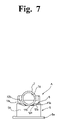
- FIG. 7 is a left side view of the hinge for portable terminal according to the present invention.
- FIG. 8 is a right side view of the hinge for portable terminal according to the present invention.
- FIG. 9 is a partial vertical cross-sectional view showing an internal mechanism of the hinge for portable terminal according to the present invention.
- FIG. 10 is a vertical cross-sectional view showing the state when a rotary hinge part of the hinge for portable terminal according to the present invention is turned 90°;
- FIG. 11 is a partial front cross-sectional view showing the mounting state of an opening/closing hinge part of the hinge for portable terminal according to the present invention.
- FIG. 12 is a left side view of the opening/closing hinge part of the hinge for portable terminal according to the present invention.
- FIG. 13 is a vertical cross-sectional view showing the mounting state of the opening/closing hinge part of the hinge for portable terminal according to the present invention.
- FIG. 14 is a plane view of a fixed member of the rotary hinge part of the hinge for portable terminal according to the present invention.
- FIG. 15 is a developed view of a first cam portion of the fixed member of the rotary hinge part of the hinge for portable terminal according to the present invention.
- FIG. 16 is a bottom view of the rotary member of the rotary hinge part of the hinge for portable terminal according to the present invention.
- FIG. 17 is a left side view of a cam portion of the opening/closing hinge part of the hinge for portable terminal according to the present invention.
- FIG. 18 is a developed view of the cam portion shown in FIG. 17 ;
- FIG. 19 is a right side view of a cam floor of the opening/closing hinge part of the hinge for portable terminal according to the present invention.
- FIG. 20 is a developed view of the cam portion of the cam floor shown in FIG. 17 ;
- FIG. 21 is an explanatory view to explain the operation of the rotary hinge part of the hinge for portable terminal according to the present invention.
- FIG. 22 is an explanatory view to explain the operation of the opening/closing hinge part of the hinge for portable terminal according to the present invention.
- FIG. 1 to FIG. 3 show a cellular phone B of a foldable type which is a kind of a portable terminal using a hinge A for portable terminal according to the present invention.
- the reference numeral 1 denotes a first casing having a keyboard portion 1 a and a microphone 1 b thereon
- the reference numeral 2 denotes a second casing having a display portion 2 a , a speaker 2 b , and a camera 2 c thereon.
- the first casing 1 and the second casing 2 are coupled to each other at respective ends thereof via the hinge A for portable terminal to be turnable in a horizontal direction and openable/closable in a vertical direction relative to each other.
- This hinge A for portable terminal is composed of a rotary hinge part 3 and an opening/closing hinge part 4 .
- the rotary hinge part 3 is attached to an upper face of the end portion of the first casing 1 to turn the second casing 2 in the horizontal direction relative to the first casing 1 .
- the opening/closing hinge part 4 is attached to the rotary hinge part 3 to open/close the second casing 2 in the vertical direction relative to the first casing 1 .
- Mounting portions 2 d , 2 e of the second casing 2 are attached to the opening/closing hinge part 4 .
- the rotary hinge part 3 is composed of a fixed member 5 and a cylindrical rotary member 7 .
- the fixed member 5 has a pivotally supporting cylinder 5 b including a mounting base 5 a which is attached to the upper face of the end portion of the first casing 1 with fixing screws 5 c , 5 c , . . . .
- the rotary member 7 is turnably attached at its substantially center portion to the pivotally supporting cylinder 5 b of the fixed member 5 via a hinge shaft 6 .
- the hinge shaft 6 has a flange portion 6 a at a lower end portion thereof inserted in the pivotally supporting cylinder 5 b , and also has a deformed portion 6 b at an upper end portion thereof.
- the deformed portion 6 b is inserted in a deformed mounting hole 7 a formed in a substantially center portion of the rotary member 7 , and the end portion is calked, so that the hinge shaft 6 is fixed to the rotary member 7 .
- the reference numeral 9 denotes a first cam mechanism of the rotary hinge part 3 side, and as shown especially in FIG. 14 to FIG. 16 , this first cam mechanism 9 is composed of: a first cam portion 11 provided on an upper periphery of the pivotally supporting cylinder 5 b of the fixed member 5 and constituted of protruding portions 11 a , 11 a and recessed portions 11 b , 11 b ; a second cam portion 12 provided on a side of the rotary member 7 facing the first cam portion 11 and similarly constituted of protruding portions 12 a , 12 a and recessed portions 12 b , 12 b ; and a first resilient means 13 for pressing the second cam portion 12 to the first cam portion 11 , the first resilient means 13 being constituted of a compression spring which is coiled around the hinge shaft 6 to be resiliently interposed between the flange portion 6 a of the hinge shaft 6 and an inner wall 5 d on an upper end side of the pivotally supporting cylinder 5 b.
- the opening/closing hinge part 4 is set in the cylindrical rotary member 7 , and it includes: an opening/closing member 16 which has turn stoppers 16 a , 16 a extending on an outer periphery thereof in an axial direction and which is constituted of a hinge cylinder fittingly inserted in an insertion cylinder portion 7 b having a turn stopper 7 c in a protruding ridge shape provided on one of inner sides of the rotary member 7 ; a hinge pin 17 that has a deformed head portion 17 a fitted in a side wall 16 c of the opening/closing member 16 and passes through a center portion of the opening/closing member 16 in an axial direction to have a free end side thereof protrude from an open end side as especially shown in FIG.
- a second cam 18 provided at the free end side of the hinge pin 17 and having at a center portion thereof an insertion hole 18 a through which the hinge pin 17 is rotatably inserted; a cam floor 19 that similarly has at a center portion thereof an insertion hole 19 a which is formed in an axial direction and through which the hinge pin 17 is inserted and that is inserted in the opening/closing member 16 to be slidable in the axial direction with a rotation thereof restricted by the opening/closing member 16 ; and a second resilient means 20 constituted of a compression spring coiled around the hinge pin 17 to be resiliently interposed between the side wall 16 c of the opening/closing member 16 and the cam floor 19 .
- a means for having the cam floor 19 caught by the opening/closing member 16 is composed of a pair of key portions 19 b , 19 b protruding from an outer periphery of the cam floor 19 as shown especially in FIG. 19 and key grooves 16 b , 16 b provided in the opening/closing member 16 as shown especially in FIG. 11 and FIG. 13 so as to have the key portions 19 b , 19 b fitted therein.
- a second cam mechanism 15 composed of cam portions 21 , 22 formed of protruding portions 21 a , 21 a / 22 a , 22 a and recessed portions 21 b , 21 b / 22 b , 22 b as shown in FIG. 9 , FIG. 11 , and FIG. 17 to FIG. 20 , and the cam portions 21 , 22 are brought into pressure contact with each other by the second resilient means 20 as shown in FIG. 13 .
- the reference numeral 14 denotes an E ring, and this E ring 14 , when fitted in a peripheral groove 17 b provided along an end portion of the hinge pin 17 , locks the hinge pin 17 so as to prevent the hinge pin 17 from coming off the opening/closing member 16 as shown especially in FIG. 13 .
- the mounting base 5 a of the fixed member 5 of the rotary hinge part 3 of the hinge A for portable terminal according to the present invention is fixed to the upper face of the upper end of the first casing 1 , using the fixing screws 5 c , 5 c . . . as shown in FIG. 1 and FIG. 3 .
- the second cam 18 protruding from the opening/closing member 16 of the opening/closing hinge part 4 is coupled to a coupling hole 2 f (see FIG.
- the second casing 2 is turnable in a right and a left direction up to 90° each, totally 180°, at whatever opening/closing angle it is positioned by the opening/closing hinge part 4 .
- This turn angle is controlled by a stopper piece 5 e provided on an upper end of the pivotally supporting cylinder 5 b and a curved guide groove 7 e which is provided on a bottom face of the rotary member 7 and in which the stopper piece 5 e is fittingly inserted, as shown in FIG. 4 to FIG. 14 and FIG.
- the protruding portions 11 a , 11 a of the cam portion 11 provided on a rotary member 7 side run on the protruding portions 12 a , 12 a of the cam portion 12 provided on the fixed member 5 side, so that the second casing 2 is slightly lifted up as shown especially in FIG. 10 . Therefore, the upper face of the first casing 1 and the lower face of the second casing 2 are not rubbed by each other, and thus are not scratched.
- the second casing 2 is automatically opened by an absorbing function from an instant when the turn angle thereof in the right or left direction reaches 30° prior to 90°, due to facing positions of the protruding portions 11 a , 11 a and the recessed portions 11 b , 11 b of the first cam portion 11 provided on the upper end of the pivotally supporting cylinder 5 b relative to the protruding portions 12 a , 12 a and the recessed portions 12 b , 12 b of the second cam portion 12 provided on the lower side of the rotary member 7 .
- FIG. 21 is an explanatory view to explain the operation described above. Note that the sides and the positions where the protruding portions and the recessed portions of the respective cam portions 11 , 12 are provided may be reverse to those in this embodiment.
- an absorbing function works from an instant 10° prior to the maximum opening angle 180° and from an instant similarly 10° prior to the closing angle 0° to result in automatic opening/closing, and in addition, the absorbing function also works between 140° and 150°, depending on the relative facing positions of the protruding portions 21 a , 21 a / 22 a , 22 a and the recessed portions 21 b , 21 b / 22 b , 22 b constituting the respective cam portions 21 , 22 .
- a free-stop function works. Specifically, the second casing 2 is automatically closed or opened when the protruding portions 21 a , 21 a of the cam portion 21 of the second cam 18 drop in the recessed portions 22 b , 22 b of the cam portion 22 of the cam floor 19 .
- the free-stop function works when the protruding portions 21 a , 21 a of the cam portion 21 of the second cam 18 are in pressure contact with the protruding portions 22 a , 22 a of the cam portion 22 of the cam floor 19 . This operation is explained in FIG. 22 .
- a lock state is produced when the protruding portions 21 a , 21 a of the cam portion 21 of the second cam 18 drop in the recessed portions 22 b , 22 b of the cam portion 22 of the cam floor 19 .
- the sides and positions where the protruding portions and recessed portions of the respective cam portions 21 , 22 are provided may be reverse to those of this embodiment.
- the hinge according to the present invention is structured such that the rotary member 7 is turnable, in other words, the second casing 2 is turnable relative to the first casing 1 at whatever opening/closing angle between 0° and 180° they are.
- This allows the second casing 2 to be bent at an arbitrary angle relative to the first casing 1 , which realizes not only good operability in picking up a laterally wide image of a subject by a camera but also good visibility in viewing a laterally wide image displayed on a screen of the display portion.
- a cellular phone is described as an example of a portable terminal, but the hinge for portable terminal according to the present invention is also usable as it is as a hinge for a PHS, a personal digital assistance (PDA), and the like other than the cellular phone.
- PDA personal digital assistance
- the opening/closing hinge part 4 may be structured such that the opening/closing member 16 itself is rotatable and is coupled to the mounting portion side of the second casing 2 , and the cam floor 19 side is locked by the rotary member 7 side.
- the rotary hinge part 3 may of course have the similar structure as that of the opening/closing hinge part 4 , and the opening/closing member 16 of the opening/closing hinge part 4 may be a second hinge pin, instead of the hinge cylinder, on which the second cam mechanism is made to act.
- the first casing having the keyboard portion thereon and the second casing having the display portion thereon of the portable terminal are not only foldable via the opening/closing hinge part with the keyboard portion and the display portion facing each other when not in use but also openable/closable.
- the second casing having the display portion is turned relative to the first casing via the rotary hinge part in a perpendicular direction to the opening/closing direction when necessary. This allows the use of the display portion both in a vertically long state and in a laterally long state.
Abstract
To provide, in a portable terminal such as a cellular phone, especially of a foldable type, a hinge for portable terminal that not only has both functions of allowing a second casing having a display portion to turn in a horizontal direction relative to a first casing having a keyboard portion and of allowing the second casing to open/close relative to the first casing, but also is capable of preventing external leakage of a lubricating oil and is formed to be as compact as possible so that a mounting space can be saved. The hinge for portable terminal is a hinge coupling a first casing having a keyboard portion and a second casing having a display portion to each other, including: a rotary hinge part to which the first casing is coupled to be turnable relative to the second casing; and an opening/closing hinge part to which the second casing is coupled to be openable/closable relative to the first casing, wherein: the rotary hinge part has a fixed member attached to the first casing and a rotary member attached to the fixed member with a turn thereof being controlled via a first cam mechanism; and the opening/closing hinge part is provided in the rotary member and has an opening/closing member which is rotatably mounted with a rotation thereof being controlled to be in a perpendicular direction to a direction of the turn of the rotary hinge part via a second cam mechanism and to which an end portion of the second casing is coupled.
Description
1. Field of the Invention
The present invention relates to a hinge for portable terminal suitable for use in portable terminals such as a cellular phone, a PHS, and a small computer.
2. Description of the Related Art
In recent years, the function and performance of portable terminals are getting remarkably higher and the portable terminals are becoming more compact. Among them, as for a cellular phone, a PHS, and the like, in particular, the following structure is becoming on the mainstream in order to realize, when not in use, the compact size, the protection of a keyboard portion and a display portion, and further, the prevention of the malfunction of the keyboard portion. That is, a first casing having the keyboard portion and a microphone thereon and a second casing having the display portion and a speaker thereon are foldable via a hinge, with the keyboard portion and the display portion facing each other. In such a cellular phone, PHS, or the like, the display portion is formed to be vertically long so as to have a slim shape. However, now that the portable terminals are additionally equipped with various functions, for example, a downloaded movie display function and a television image display function, such a vertically long display portion is in some cases poor in visibility for those who are used to viewing a laterally long screen such as a screen of a television, a movie, a personal computer, or the like. Moreover, there has also arisen a problem such that, when information originally assumed to be displayed on a laterally long display portion is transmitted or inputted to a portable terminal having such a vertically long display portion, the information cannot be completely displayed thereon.
This has given rise to a need for a hinge that not only foldably couples the second casing to the first casing, but also allows the second casing to turn relative to the first casing in a direction perpendicular to an opening/closing direction when it is at a predetermined opening/closing position.
As a hinge having such a function, that described in Japanese Patent Application Laid-open No. 2003-69676 is known.
The hinge described in this patent application publication is structured such that a circulation spindle part of a rotary hinge part that is pivotally attached to a bottom of a first casing is bent to be led to an upper end side of a second casing and an opening/closing hinge part coupled to the second casing is attached to an upper end portion of the circulation spindle part. This structure has such a problem that a lubricating oil especially in the rotary hinge part leaks outside to stain hands and clothes, and in addition, the structure of the entire hinge becomes large to occupy a large mounting space, which hinders the downsizing of the portable terminal.
It is an object of the present invention to provide, in a portable terminal such as a cellular phone, especially of a foldable type, a hinge for portable terminal which not only has both functions of allowing a second casing having a display portion thereon to turn in a horizontal direction relative to a first casing having a keyboard portion thereon and of allowing the second casing to open/close relative to the first casing, but also is capable of preventing a lubricating oil from leaking outside and is formed as compact as possible so that a mounting space can be saved.
In order to achieve the object stated above, the present invention is a hinge coupling a first casing on which a keyboard portion is provided and a second casing on which a display portion is provided to each other, including: a rotary hinge part to which the first casing is coupled to be turnable relative to the second casing; and an opening/closing hinge part to which the second casing is coupled to be openable/closable relative to the first casing, wherein: the rotary hinge part has a fixed member attached to the first casing and a rotary member attached to the fixed member with a turn thereof being controlled via a first cam mechanism; and the opening/closing hinge part is provided in the rotary member and has an opening/closing member which is rotatably mounted with a rotation thereof being controlled to be in a perpendicular direction to a direction of the turn of the rotary hinge part via a second cam mechanism and to which an end portion of the second casing is coupled.
In the above-described invention, the first cam mechanism may include: a first cam portion provided at an upper end of the fixed member; a hinge shaft inserted through a pivotally supporting cylinder of the fixed member in an axial direction; a second cam portion provided at a position facing the first cam portion on a lower face of the rotary member attached to an upper end portion of the hinge shaft; and a resilient means for bringing the second cam portion into pressure contact with the first cam portion provided on the fixed member side, the resilient means being resiliently provided between the hinge shaft and the pivotally supporting cylinder.
The above-described invention may also be structured such that at least one of the first cam mechanism and the second cam mechanism has an absorbing function, the absorbing function of the first cam mechanism being a function of automatically turning the rotary member from a predetermined turn angle, and the absorbing function of the second cam mechanism being a function of automatically opening/closing the opening/closing member from a predetermined opening/closing angle.
The above-described invention may also be structured such that the rotary hinge part is allowed to operate from an instant when the opening/closing hinge part is opened to a predetermined angle.
The above-described invention may also be structured such that the opening/closing member is a hinge cylinder.
The above-described invention may further include a means for allowing the rotary hinge part to operate from the instant when the opening/closing hinge part is opened to the predetermined angle, the means being provided between the opening/closing member of the opening/closing hinge part and the fixed member of the rotary hinge part.
The above-described invention may be structured such that each of the first cam mechanism and the second cam mechanism is constituted of a cam and a cam floor in which cam portions are formed on respective facing surfaces thereof, one of the cam portions being in pressure contact with the other cam portion.
The above-described structure of the present invention can bring about the following effects. It is possible to prevent a screen from being scratched as much as possible when not in use since a face of the second casing where a display portion and a camera are provided is positioned on a lower side while the second casing is folded relative to the first casing. In addition, the second casing is allowed to open/close in a vertical direction by the opening/closing hinge part and is turnable in a horizontal direction while the opening/closing hinge part is opened, thereby facilitating the use of the display portion in a laterally long state.
This hinge A for portable terminal is composed of a rotary hinge part 3 and an opening/closing hinge part 4. The rotary hinge part 3 is attached to an upper face of the end portion of the first casing 1 to turn the second casing 2 in the horizontal direction relative to the first casing 1. The opening/closing hinge part 4 is attached to the rotary hinge part 3 to open/close the second casing 2 in the vertical direction relative to the first casing 1. Mounting portions 2 d, 2 e of the second casing 2 are attached to the opening/closing hinge part 4.
As shown especially in FIG. 1 to FIG. 10 , the rotary hinge part 3, out of these components, is composed of a fixed member 5 and a cylindrical rotary member 7. The fixed member 5 has a pivotally supporting cylinder 5 b including a mounting base 5 a which is attached to the upper face of the end portion of the first casing 1 with fixing screws 5 c, 5 c, . . . . The rotary member 7 is turnably attached at its substantially center portion to the pivotally supporting cylinder 5 b of the fixed member 5 via a hinge shaft 6. The hinge shaft 6 has a flange portion 6 a at a lower end portion thereof inserted in the pivotally supporting cylinder 5 b, and also has a deformed portion 6 b at an upper end portion thereof. The deformed portion 6 b is inserted in a deformed mounting hole 7 a formed in a substantially center portion of the rotary member 7, and the end portion is calked, so that the hinge shaft 6 is fixed to the rotary member 7.
The reference numeral 9 denotes a first cam mechanism of the rotary hinge part 3 side, and as shown especially in FIG. 14 to FIG. 16 , this first cam mechanism 9 is composed of: a first cam portion 11 provided on an upper periphery of the pivotally supporting cylinder 5 b of the fixed member 5 and constituted of protruding portions 11 a, 11 a and recessed portions 11 b, 11 b; a second cam portion 12 provided on a side of the rotary member 7 facing the first cam portion 11 and similarly constituted of protruding portions 12 a, 12 a and recessed portions 12 b, 12 b; and a first resilient means 13 for pressing the second cam portion 12 to the first cam portion 11, the first resilient means 13 being constituted of a compression spring which is coiled around the hinge shaft 6 to be resiliently interposed between the flange portion 6 a of the hinge shaft 6 and an inner wall 5 d on an upper end side of the pivotally supporting cylinder 5 b.
Next, as shown in FIG. 8 to FIG. 13 , the opening/closing hinge part 4 is set in the cylindrical rotary member 7, and it includes: an opening/closing member 16 which has turn stoppers 16 a, 16 a extending on an outer periphery thereof in an axial direction and which is constituted of a hinge cylinder fittingly inserted in an insertion cylinder portion 7 b having a turn stopper 7 c in a protruding ridge shape provided on one of inner sides of the rotary member 7; a hinge pin 17 that has a deformed head portion 17 a fitted in a side wall 16 c of the opening/closing member 16 and passes through a center portion of the opening/closing member 16 in an axial direction to have a free end side thereof protrude from an open end side as especially shown in FIG. 13 ; a second cam 18 provided at the free end side of the hinge pin 17 and having at a center portion thereof an insertion hole 18 a through which the hinge pin 17 is rotatably inserted; a cam floor 19 that similarly has at a center portion thereof an insertion hole 19 a which is formed in an axial direction and through which the hinge pin 17 is inserted and that is inserted in the opening/closing member 16 to be slidable in the axial direction with a rotation thereof restricted by the opening/closing member 16; and a second resilient means 20 constituted of a compression spring coiled around the hinge pin 17 to be resiliently interposed between the side wall 16 c of the opening/closing member 16 and the cam floor 19.
Incidentally, a means for having the cam floor 19 caught by the opening/closing member 16 is composed of a pair of key portions 19 b, 19 b protruding from an outer periphery of the cam floor 19 as shown especially in FIG. 19 and key grooves 16 b, 16 b provided in the opening/closing member 16 as shown especially in FIG. 11 and FIG. 13 so as to have the key portions 19 b, 19 b fitted therein. On mutually facing surfaces of the second cam 18 and the cam floor 19, provided is a second cam mechanism 15 composed of cam portions 21, 22 formed of protruding portions 21 a, 21 a/22 a, 22 a and recessed portions 21 b, 21 b/22 b, 22 b as shown in FIG. 9 , FIG. 11 , and FIG. 17 to FIG. 20 , and the cam portions 21, 22 are brought into pressure contact with each other by the second resilient means 20 as shown in FIG. 13 .
As shown in FIG. 4 to FIG. 13 , the reference numeral 14 denotes an E ring, and this E ring 14, when fitted in a peripheral groove 17 b provided along an end portion of the hinge pin 17, locks the hinge pin 17 so as to prevent the hinge pin 17 from coming off the opening/closing member 16 as shown especially in FIG. 13 .
Here, the mounting base 5 a of the fixed member 5 of the rotary hinge part 3 of the hinge A for portable terminal according to the present invention is fixed to the upper face of the upper end of the first casing 1, using the fixing screws 5 c, 5 c . . . as shown in FIG. 1 and FIG. 3 . The second cam 18 protruding from the opening/closing member 16 of the opening/closing hinge part 4 is coupled to a coupling hole 2 f (see FIG. 11 ) of the mounting portion 2 d out of the mounting portions 2 d, 2 e provided on an upper end portion of the second casing 2, utilizing turn stoppers 18 b of the second cam 18, and the opening/closing hinge part 4 is coupled to the other mounting portion 2 e via a third hinge pin 25 inserted in the mounting cylinder portion 7 d.
With this structure, if an attempt is made to turn the second casing 2 in the horizontal direction relative to the first casing 1 while the first casing 1 and the second casing 2 are in a closed state as shown in FIG. 1 and FIG. 2 , the second casing 2 is turnable in a right and a left direction up to 90° each, totally 180°, at whatever opening/closing angle it is positioned by the opening/closing hinge part 4. This turn angle is controlled by a stopper piece 5 e provided on an upper end of the pivotally supporting cylinder 5 b and a curved guide groove 7 e which is provided on a bottom face of the rotary member 7 and in which the stopper piece 5 e is fittingly inserted, as shown in FIG. 4 to FIG. 14 and FIG. 16 . At this time, the protruding portions 11 a, 11 a of the cam portion 11 provided on a rotary member 7 side run on the protruding portions 12 a, 12 a of the cam portion 12 provided on the fixed member 5 side, so that the second casing 2 is slightly lifted up as shown especially in FIG. 10 . Therefore, the upper face of the first casing 1 and the lower face of the second casing 2 are not rubbed by each other, and thus are not scratched.
Further, in this embodiment, the second casing 2 is automatically opened by an absorbing function from an instant when the turn angle thereof in the right or left direction reaches 30° prior to 90°, due to facing positions of the protruding portions 11 a, 11 a and the recessed portions 11 b, 11 b of the first cam portion 11 provided on the upper end of the pivotally supporting cylinder 5 b relative to the protruding portions 12 a, 12 a and the recessed portions 12 b, 12 b of the second cam portion 12 provided on the lower side of the rotary member 7. Specifically, automatic closing is performed when the protruding portions 12 a, 12 a of the second cam portion 12 of the rotary member 7 side drop in the recessed portions 11 b, 11 b of the first cam portion 11 of the pivotally supporting cylinder 5 b side due to the turn angle thereof, and in the other state, namely, while the protruding portions 12 a, 12 a of the second cam portion 12 and the protruding portions 11 a, 11 a of the first cam portion 11 are facing each other to be in pressure contact with each other, a free-stop function works. A lock state is produced when the protruding portions 12 a, 12 a of the second cam portion 12 drop in the recessed portions 11 b, 11 b of the first cam portion 11. FIG. 21 is an explanatory view to explain the operation described above. Note that the sides and the positions where the protruding portions and the recessed portions of the respective cam portions 11, 12 are provided may be reverse to those in this embodiment.
Next, the opening/closing operation by the opening/closing hinge part 4 is performed while being controlled by the respective cam portions 21, 22 of the second cam 18 and the cam floor 19. In this embodiment, owing to a resilient force of the second resilient means 20, an absorbing function works from an instant 10° prior to the maximum opening angle 180° and from an instant similarly 10° prior to the closing angle 0° to result in automatic opening/closing, and in addition, the absorbing function also works between 140° and 150°, depending on the relative facing positions of the protruding portions 21 a, 21 a/22 a, 22 a and the recessed portions 21 b, 21 b/22 b, 22 b constituting the respective cam portions 21, 22. Between the opening angles 10° and 170°, a free-stop function works. Specifically, the second casing 2 is automatically closed or opened when the protruding portions 21 a, 21 a of the cam portion 21 of the second cam 18 drop in the recessed portions 22 b, 22 b of the cam portion 22 of the cam floor 19. The free-stop function works when the protruding portions 21 a, 21 a of the cam portion 21 of the second cam 18 are in pressure contact with the protruding portions 22 a, 22 a of the cam portion 22 of the cam floor 19. This operation is explained in FIG. 22 .
A lock state is produced when the protruding portions 21 a, 21 a of the cam portion 21 of the second cam 18 drop in the recessed portions 22 b, 22 b of the cam portion 22 of the cam floor 19. The sides and positions where the protruding portions and recessed portions of the respective cam portions 21, 22 are provided may be reverse to those of this embodiment.
The hinge according to the present invention is structured such that the rotary member 7 is turnable, in other words, the second casing 2 is turnable relative to the first casing 1 at whatever opening/closing angle between 0° and 180° they are. This allows the second casing 2 to be bent at an arbitrary angle relative to the first casing 1, which realizes not only good operability in picking up a laterally wide image of a subject by a camera but also good visibility in viewing a laterally wide image displayed on a screen of the display portion.
In the above embodiment, a cellular phone is described as an example of a portable terminal, but the hinge for portable terminal according to the present invention is also usable as it is as a hinge for a PHS, a personal digital assistance (PDA), and the like other than the cellular phone.
The opening/closing hinge part 4 may be structured such that the opening/closing member 16 itself is rotatable and is coupled to the mounting portion side of the second casing 2, and the cam floor 19 side is locked by the rotary member 7 side.
Further, the rotary hinge part 3 may of course have the similar structure as that of the opening/closing hinge part 4, and the opening/closing member 16 of the opening/closing hinge part 4 may be a second hinge pin, instead of the hinge cylinder, on which the second cam mechanism is made to act.
As has been detailed hitherto, with the rotary hinge part and the opening/closing hinge part that are integrated to have a compact structure, the first casing having the keyboard portion thereon and the second casing having the display portion thereon of the portable terminal are not only foldable via the opening/closing hinge part with the keyboard portion and the display portion facing each other when not in use but also openable/closable. In addition, when they are opened for use, the second casing having the display portion is turned relative to the first casing via the rotary hinge part in a perpendicular direction to the opening/closing direction when necessary. This allows the use of the display portion both in a vertically long state and in a laterally long state.
Claims (7)
1. A hinge for portable terminal coupling a first casing on which a keyboard portion is provided and a second casing on which a display portion is provided to each other, comprising:
a rotary hinge part to which the first casing is coupled to be turnable relative to the second casing in a horizontally direction; and
an opening/closing hinge part to which the second casing is coupled to be openable/closable relative to the first casing in a vertical direction;
wherein said rotary hinge part composed of a fixed member having a pivotally supporting cylinder and a mounting base which is attached to the upper face of the first casing, a hinge shaft inserted through the pivotally supporting cylinder in an axial direction, and a rotary member attached to the hinge shaft with a turn thereof being controlled via a first cam mechanism;
wherein said opening/closing hinge part is provided in said rotary member and has an opening/closing member which is rotatably mounted with a rotation thereof being controlled, to be in a perpendicular direction to a direction of the turn of said rotary hinge part via a second cam mechanism and to which an end portion of the second casing is coupled;
wherein said first cam mechanism includes a first cam portion provided at an upper end of said rotary supporting cylinder, a second cam portion provided at a position facing said first cam portion on a lower face of said rotary member, and a resilient means for bringing said second cam portion into pressure contact with said first cam portion, said resilient means being resiliently provided between a flange portion of the hinge shaft and the pivotally supporting cylinder.
2. The hinge for portable terminal according to claim 1 , wherein at least one of said first cam mechanism and said second cam mechanism has an absorbing function, the absorbing function of said first cam mechanism being a function of automatically turning said rotary member from a predetermined turn angle, and the absorbing function of said second cam mechanism being a function of automatically opening/closing said opening/closing member from a predetermined opening/closing angle.
3. The hinge for portable terminal according to claim 1 , wherein said rotary hinge part is allowed to operate from an instant when said opening/closing hinge part is opened to a predetermined angle.
4. The hinge for portable terminal according to claim 1 , wherein said opening/closing member is a hinge cylinder.
5. The hinge for portable terminal according to claim 3 , further comprising a means for allowing said rotary hinge part to operate from the instant when said opening/closing hinge part is opened to the predetermined angle, the means being provided between said opening/closing member of said opening/closing hinge part and said fixed member of said rotary hinge part.
6. The hinge for portable terminal according to claim 1 , wherein each of said first cam mechanism and said second cam mechanism is constituted of a cam and a cam floor in which cam portions are formed on respective facing surfaces thereof, one of the cam portions being in pressure contact with the other cam portion.
7. The hinge for portable terminal according to claim 1 , wherein said first cam and said second cam each having protruding portions and recessed portions so that when said each protruding portions abut against each other, said hinge shaft slightly lifted up with the rotary member against the resilient means.
Applications Claiming Priority (2)
| Application Number | Priority Date | Filing Date | Title |
|---|---|---|---|
| JP2003286282A JP2005054890A (en) | 2003-08-04 | 2003-08-04 | Hinge for portable terminal |
| JP2003-286282 | 2003-08-23 |
Publications (2)
| Publication Number | Publication Date |
|---|---|
| US20050055806A1 US20050055806A1 (en) | 2005-03-17 |
| US7055219B2 true US7055219B2 (en) | 2006-06-06 |
Family
ID=34269031
Family Applications (1)
| Application Number | Title | Priority Date | Filing Date |
|---|---|---|---|
| US10/903,726 Expired - Fee Related US7055219B2 (en) | 2003-08-04 | 2004-07-30 | Hinge for portable terminal |
Country Status (5)
| Country | Link |
|---|---|
| US (1) | US7055219B2 (en) |
| JP (1) | JP2005054890A (en) |
| KR (1) | KR100630424B1 (en) |
| CN (1) | CN1303858C (en) |
| TW (1) | TWI261453B (en) |
Cited By (23)
| Publication number | Priority date | Publication date | Assignee | Title |
|---|---|---|---|---|
| US20040224729A1 (en) * | 2002-12-06 | 2004-11-11 | Nec Corporation | Wiring structure for folding portable device |
| US20060034450A1 (en) * | 2004-08-11 | 2006-02-16 | Ming-Shiung Chang | Electrical device for adjusting the angle between a top module and a bottom module |
| US20060044747A1 (en) * | 2004-08-27 | 2006-03-02 | Wen-Tsan Chen | Electrical device for adjusting the angle between a top module and a bottom module |
| US20060101772A1 (en) * | 2004-09-24 | 2006-05-18 | Nec Corporation | Folding electronic device, connecting component and camera unit |
| US20060162123A1 (en) * | 2005-01-25 | 2006-07-27 | Samsung Electronics Co., Ltd. | Hinge device for a display for rotation type mobile phone |
| US20060218750A1 (en) * | 2005-03-31 | 2006-10-05 | Hideya Tajima | Biaxial hinge device of electrical equipment |
| US20070037616A1 (en) * | 2005-08-09 | 2007-02-15 | Kuo-Wei Hung | Hinge and mobile phone with the hinge |
| US20080064452A1 (en) * | 2006-09-07 | 2008-03-13 | Samsung Electronics Co., Ltd. | Hinge device having a plurality of axes for a portable terminal and a connection member having the plurality of axes |
| US20080081591A1 (en) * | 2006-10-02 | 2008-04-03 | Samsung Electronics Co., Ltd. | Semi-automatic swing device for swing-type portable terminal |
| US20080141125A1 (en) * | 2006-06-23 | 2008-06-12 | Firooz Ghassabian | Combined data entry systems |
| US20080167086A1 (en) * | 2007-01-05 | 2008-07-10 | Samsung Electronics Co. Ltd. | Portable terminal for providing visual and acoustic convenience and rotary type hinge apparatus therefor |
| US20090037623A1 (en) * | 1999-10-27 | 2009-02-05 | Firooz Ghassabian | Integrated keypad system |
| US20090040707A1 (en) * | 2003-10-23 | 2009-02-12 | Sony Corporation | Electronic device |
| US20090146848A1 (en) * | 2004-06-04 | 2009-06-11 | Ghassabian Firooz Benjamin | Systems to enhance data entry in mobile and fixed environment |
| US20090199092A1 (en) * | 2005-06-16 | 2009-08-06 | Firooz Ghassabian | Data entry system |
| US20090257817A1 (en) * | 2008-04-10 | 2009-10-15 | Hon Hai Precision Industry Co., Ltd. | Rotary device |
| US20100154170A1 (en) * | 2008-12-19 | 2010-06-24 | Shin Zu Shing Co., Ltd. | Hinge and an electronic device with the hinge |
| US20100154166A1 (en) * | 2008-12-24 | 2010-06-24 | Shin Zu Shing Co., Ltd. | Hinge and an electronic device with the hinge |
| US20100154169A1 (en) * | 2008-12-19 | 2010-06-24 | Shin Zu Shing Co., Ltd. | Hinge and an electronic device with the hinge |
| US20100246130A1 (en) * | 2009-03-24 | 2010-09-30 | Jeffrey Paquette | Translating Hinge |
| US20100302163A1 (en) * | 2007-08-31 | 2010-12-02 | Benjamin Firooz Ghassabian | Data entry system |
| US20110067743A1 (en) * | 2009-09-19 | 2011-03-24 | Yang Pan | Intelligent Solar Panel Array |
| US20110232044A1 (en) * | 2010-03-26 | 2011-09-29 | Hsi-Hsin Chen | Resilient rotation buckle |
Families Citing this family (18)
| Publication number | Priority date | Publication date | Assignee | Title |
|---|---|---|---|---|
| TW578854U (en) * | 2003-04-11 | 2004-03-01 | Hon Hai Prec Ind Co Ltd | Hinge device |
| JP2005054891A (en) * | 2003-08-04 | 2005-03-03 | Kato Electrical Mach Co Ltd | Hinge for portable terminal |
| JP2005054890A (en) * | 2003-08-04 | 2005-03-03 | Kato Electrical Mach Co Ltd | Hinge for portable terminal |
| TWM243864U (en) * | 2003-09-26 | 2004-09-11 | Hon Hai Prec Ind Co Ltd | Rotary type hinge mechanism |
| TWM274472U (en) * | 2005-01-25 | 2005-09-01 | Nano Prec Corp | Torque adjusting module |
| CN100448336C (en) * | 2005-07-07 | 2008-12-31 | 集嘉通讯股份有限公司 | Sliding structure |
| US7559117B2 (en) * | 2006-07-27 | 2009-07-14 | Shin Zu Shing Co., Ltd. | Dual-axis hinge |
| JP4582341B2 (en) * | 2006-08-31 | 2010-11-17 | 日本電気株式会社 | Biaxial hinge mechanism and portable communication terminal and electronic device using the same |
| JP4730270B2 (en) * | 2006-09-28 | 2011-07-20 | 富士フイルム株式会社 | Portable device |
| US20090186662A1 (en) * | 2008-01-18 | 2009-07-23 | Research In Motion Limited | Clamshell handheld electronic communication device with pivotally coupled interconnector |
| WO2009123619A1 (en) * | 2008-04-01 | 2009-10-08 | Hewlett-Packard Development Company, L.P. | Tablet computers having controlled hinges |
| CN101742867B (en) * | 2008-11-05 | 2011-08-31 | 宏达国际电子股份有限公司 | Electronic device |
| CN101754620B (en) * | 2008-12-12 | 2012-03-28 | 华硕电脑股份有限公司 | Electronic device |
| US20100216513A1 (en) * | 2009-02-23 | 2010-08-26 | Research In Motion Limited | Handheld electronic device with rotatable member |
| US8103322B2 (en) * | 2009-02-27 | 2012-01-24 | Research In Motion Limited | Handheld electronic device having two device members slidable relative to a bridge |
| WO2011158325A1 (en) * | 2010-06-15 | 2011-12-22 | 株式会社 ストロベリーコーポレーション | Hinge device and electronic apparatus using hinge device |
| JP5891991B2 (en) * | 2012-07-31 | 2016-03-23 | 富士通株式会社 | HINGE DEVICE AND ELECTRONIC DEVICE USING THE HINGE DEVICE |
| CN109058282A (en) * | 2018-08-03 | 2018-12-21 | 张家港市凯利雅特种纺织纱线有限公司 | A kind of hinge arrangement for spandex weaving loom |
Citations (19)
| Publication number | Priority date | Publication date | Assignee | Title |
|---|---|---|---|---|
| US6347433B1 (en) * | 1999-06-18 | 2002-02-19 | Cema Technologies, Inc. | Flat panel display tilt and swivel mechanism |
| JP2002139020A (en) * | 2000-11-07 | 2002-05-17 | Haimekku:Kk | Small hinge |
| US6549789B1 (en) * | 2000-04-28 | 2003-04-15 | Motorola Inc. | Portable electronic device with an adaptable user interface |
| US6658272B1 (en) * | 2000-04-28 | 2003-12-02 | Motorola, Inc. | Self configuring multiple element portable electronic device |
| US6697117B1 (en) * | 1997-12-23 | 2004-02-24 | Samsung Electronics Co., Ltd. | Folded compact image capture apparatus |
| US6742221B2 (en) * | 2002-11-06 | 2004-06-01 | Shin Zu Shing Co., Ltd. | Hinge for a notebook computer |
| US6798646B2 (en) * | 2003-02-14 | 2004-09-28 | Lite-On Technology Corporation | Rotary axle structure for portable computers |
| US20040198474A1 (en) * | 2003-04-01 | 2004-10-07 | Samsung Electro-Mechanics Co., Ltd. | Cellular phone and automatic revolution method thereof |
| US20040203535A1 (en) * | 2003-04-14 | 2004-10-14 | Samsung Electronics Co., Ltd. | Mobile phone having a rotational camera lens housing |
| US6804861B2 (en) * | 2002-12-04 | 2004-10-19 | Lite-On Technology Corp. | Rotation shaft mechanism of display portion of portable computer |
| JP2004304458A (en) * | 2003-03-31 | 2004-10-28 | Sanyo Electric Co Ltd | Foldable portable terminal device |
| US6839576B2 (en) * | 2002-12-30 | 2005-01-04 | Motorola, Inc. | Multiple axis hinge assembly |
| US6845546B1 (en) * | 2003-06-20 | 2005-01-25 | Shin Zu Shing Co., Ltd. | Hinge assembly with a rotation seat available to rotate in both latitudinal and longitudinal directions with respect to a fixing seat |
| US20050054396A1 (en) * | 2003-08-22 | 2005-03-10 | Lg Electronics Inc. | Folder type mobile phone |
| US20050064919A1 (en) * | 2003-09-19 | 2005-03-24 | Ki-Chul An | Twist-type mobile terminal and hinge device thereof |
| US20050066474A1 (en) * | 2003-09-26 | 2005-03-31 | Hon Hai Precision Industry Co., Ltd. | Rotary type hinge assembly for foldable electronic device |
| US6883206B2 (en) * | 2003-01-16 | 2005-04-26 | Quanta Computer Inc. | Swivel hinge with angular fixing structure |
| US20050119023A1 (en) * | 2001-10-17 | 2005-06-02 | Hiroshi Sudo | Hinge device and cell phone using the hinge device |
| US20050245294A1 (en) * | 2004-03-30 | 2005-11-03 | Amphenol-T&M Antennas. | Dual axis hinge for handheld device |
Family Cites Families (9)
| Publication number | Priority date | Publication date | Assignee | Title |
|---|---|---|---|---|
| JP2001355371A (en) * | 2000-06-14 | 2001-12-26 | Kato Electrical Mach Co Ltd | Miniaturized hinge device |
| JP4298908B2 (en) * | 2000-11-20 | 2009-07-22 | 三菱製鋼株式会社 | Biaxial hinge having a plurality of torque generators |
| KR100526335B1 (en) * | 2000-12-28 | 2005-11-08 | 주식회사 팬택앤큐리텔 | Device For Opening And Closing Folder Of Mobile Phone |
| KR100470172B1 (en) * | 2001-06-22 | 2005-02-04 | 주식회사 임팩트라 | Mobile Station having Display Part Convertible Vertical into Horizontal |
| KR100396271B1 (en) * | 2001-08-23 | 2003-09-02 | 삼성전자주식회사 | Portable radiotelephone being automatically/manually folded |
| KR100455545B1 (en) * | 2002-06-17 | 2004-11-06 | 주식회사 엠투시스 | Cover hinge mechanism of cellular phone |
| KR100528550B1 (en) * | 2003-07-30 | 2005-11-23 | 주식회사 스카이텔레텍 | Folder type mobile communication terminal |
| JP2005054890A (en) * | 2003-08-04 | 2005-03-03 | Kato Electrical Mach Co Ltd | Hinge for portable terminal |
| JP2005054891A (en) * | 2003-08-04 | 2005-03-03 | Kato Electrical Mach Co Ltd | Hinge for portable terminal |
-
2003
- 2003-08-04 JP JP2003286282A patent/JP2005054890A/en not_active Ceased
-
2004
- 2004-02-07 KR KR1020040008116A patent/KR100630424B1/en not_active IP Right Cessation
- 2004-07-30 US US10/903,726 patent/US7055219B2/en not_active Expired - Fee Related
- 2004-08-03 TW TW093123261A patent/TWI261453B/en not_active IP Right Cessation
- 2004-08-04 CN CNB2004100557172A patent/CN1303858C/en not_active Expired - Fee Related
Patent Citations (19)
| Publication number | Priority date | Publication date | Assignee | Title |
|---|---|---|---|---|
| US6697117B1 (en) * | 1997-12-23 | 2004-02-24 | Samsung Electronics Co., Ltd. | Folded compact image capture apparatus |
| US6347433B1 (en) * | 1999-06-18 | 2002-02-19 | Cema Technologies, Inc. | Flat panel display tilt and swivel mechanism |
| US6549789B1 (en) * | 2000-04-28 | 2003-04-15 | Motorola Inc. | Portable electronic device with an adaptable user interface |
| US6658272B1 (en) * | 2000-04-28 | 2003-12-02 | Motorola, Inc. | Self configuring multiple element portable electronic device |
| JP2002139020A (en) * | 2000-11-07 | 2002-05-17 | Haimekku:Kk | Small hinge |
| US20050119023A1 (en) * | 2001-10-17 | 2005-06-02 | Hiroshi Sudo | Hinge device and cell phone using the hinge device |
| US6742221B2 (en) * | 2002-11-06 | 2004-06-01 | Shin Zu Shing Co., Ltd. | Hinge for a notebook computer |
| US6804861B2 (en) * | 2002-12-04 | 2004-10-19 | Lite-On Technology Corp. | Rotation shaft mechanism of display portion of portable computer |
| US6839576B2 (en) * | 2002-12-30 | 2005-01-04 | Motorola, Inc. | Multiple axis hinge assembly |
| US6883206B2 (en) * | 2003-01-16 | 2005-04-26 | Quanta Computer Inc. | Swivel hinge with angular fixing structure |
| US6798646B2 (en) * | 2003-02-14 | 2004-09-28 | Lite-On Technology Corporation | Rotary axle structure for portable computers |
| JP2004304458A (en) * | 2003-03-31 | 2004-10-28 | Sanyo Electric Co Ltd | Foldable portable terminal device |
| US20040198474A1 (en) * | 2003-04-01 | 2004-10-07 | Samsung Electro-Mechanics Co., Ltd. | Cellular phone and automatic revolution method thereof |
| US20040203535A1 (en) * | 2003-04-14 | 2004-10-14 | Samsung Electronics Co., Ltd. | Mobile phone having a rotational camera lens housing |
| US6845546B1 (en) * | 2003-06-20 | 2005-01-25 | Shin Zu Shing Co., Ltd. | Hinge assembly with a rotation seat available to rotate in both latitudinal and longitudinal directions with respect to a fixing seat |
| US20050054396A1 (en) * | 2003-08-22 | 2005-03-10 | Lg Electronics Inc. | Folder type mobile phone |
| US20050064919A1 (en) * | 2003-09-19 | 2005-03-24 | Ki-Chul An | Twist-type mobile terminal and hinge device thereof |
| US20050066474A1 (en) * | 2003-09-26 | 2005-03-31 | Hon Hai Precision Industry Co., Ltd. | Rotary type hinge assembly for foldable electronic device |
| US20050245294A1 (en) * | 2004-03-30 | 2005-11-03 | Amphenol-T&M Antennas. | Dual axis hinge for handheld device |
Cited By (43)
| Publication number | Priority date | Publication date | Assignee | Title |
|---|---|---|---|---|
| US20090037623A1 (en) * | 1999-10-27 | 2009-02-05 | Firooz Ghassabian | Integrated keypad system |
| US8498406B2 (en) | 1999-10-27 | 2013-07-30 | Keyless Systems Ltd. | Integrated keypad system |
| US7336782B2 (en) * | 2002-12-06 | 2008-02-26 | Nec Corporation | Wiring structure for folding portable device |
| US20040224729A1 (en) * | 2002-12-06 | 2004-11-11 | Nec Corporation | Wiring structure for folding portable device |
| US20090040707A1 (en) * | 2003-10-23 | 2009-02-12 | Sony Corporation | Electronic device |
| US8081439B2 (en) * | 2003-10-23 | 2011-12-20 | Sony Corporation | Electronic device |
| US20090146848A1 (en) * | 2004-06-04 | 2009-06-11 | Ghassabian Firooz Benjamin | Systems to enhance data entry in mobile and fixed environment |
| US20060034450A1 (en) * | 2004-08-11 | 2006-02-16 | Ming-Shiung Chang | Electrical device for adjusting the angle between a top module and a bottom module |
| US7433468B2 (en) * | 2004-08-11 | 2008-10-07 | Chi Mei Communication Systems, Inc. | Electrical device for adjusting the angle between a top module and a bottom module |
| US20060044747A1 (en) * | 2004-08-27 | 2006-03-02 | Wen-Tsan Chen | Electrical device for adjusting the angle between a top module and a bottom module |
| US7327561B2 (en) * | 2004-08-27 | 2008-02-05 | Chi Mei Communication Systems, Inc. | Electrical device for adjusting the angle between a top module and a bottom module |
| US7839996B2 (en) * | 2004-09-24 | 2010-11-23 | Nec Corporation | Folding electronic device, connecting component and camera unit |
| US20060101772A1 (en) * | 2004-09-24 | 2006-05-18 | Nec Corporation | Folding electronic device, connecting component and camera unit |
| US20060162123A1 (en) * | 2005-01-25 | 2006-07-27 | Samsung Electronics Co., Ltd. | Hinge device for a display for rotation type mobile phone |
| US7440782B2 (en) * | 2005-01-25 | 2008-10-21 | Samsung Electronics Co., Ltd. | Hinge device for a display for rotation type mobile phone |
| US20060218750A1 (en) * | 2005-03-31 | 2006-10-05 | Hideya Tajima | Biaxial hinge device of electrical equipment |
| US7478458B2 (en) * | 2005-03-31 | 2009-01-20 | Katoh Electrical Machinery Co., Ltd. | Biaxial hinge device of electrical equipment |
| US9158388B2 (en) | 2005-06-16 | 2015-10-13 | Keyless Systems Ltd. | Data entry system |
| US20090199092A1 (en) * | 2005-06-16 | 2009-08-06 | Firooz Ghassabian | Data entry system |
| US7406343B2 (en) * | 2005-08-09 | 2008-07-29 | Cheng Uei Precision Industry Co., Ltd. | Hinge and mobile phone with the hinge |
| US20070037616A1 (en) * | 2005-08-09 | 2007-02-15 | Kuo-Wei Hung | Hinge and mobile phone with the hinge |
| US20080141125A1 (en) * | 2006-06-23 | 2008-06-12 | Firooz Ghassabian | Combined data entry systems |
| US20080064452A1 (en) * | 2006-09-07 | 2008-03-13 | Samsung Electronics Co., Ltd. | Hinge device having a plurality of axes for a portable terminal and a connection member having the plurality of axes |
| US8250712B2 (en) * | 2006-09-07 | 2012-08-28 | Samsung Electronics Co., Ltd | Hinge device having a plurality of axes for a portable terminal and a connection member having the plurality of axes |
| US20080081591A1 (en) * | 2006-10-02 | 2008-04-03 | Samsung Electronics Co., Ltd. | Semi-automatic swing device for swing-type portable terminal |
| US7869840B2 (en) * | 2006-10-02 | 2011-01-11 | Samsung Electronics Co., Ltd | Semi-automatic swing device for swing-type portable terminal |
| US20080167086A1 (en) * | 2007-01-05 | 2008-07-10 | Samsung Electronics Co. Ltd. | Portable terminal for providing visual and acoustic convenience and rotary type hinge apparatus therefor |
| US8103320B2 (en) * | 2007-01-05 | 2012-01-24 | Samsung Electronics Co., Ltd | Portable terminal for providing visual and acoustic convenience and rotary type hinge apparatus therefor |
| US20100302163A1 (en) * | 2007-08-31 | 2010-12-02 | Benjamin Firooz Ghassabian | Data entry system |
| US20090257817A1 (en) * | 2008-04-10 | 2009-10-15 | Hon Hai Precision Industry Co., Ltd. | Rotary device |
| US7971321B2 (en) * | 2008-12-19 | 2011-07-05 | Shin Zu Shing Co., Ltd. | Hinge and an electronic device with the hinge |
| US7954203B2 (en) * | 2008-12-19 | 2011-06-07 | Shin Zu Shing Co., Ltd. | Hinge and an electronic device with the hinge |
| US20100154170A1 (en) * | 2008-12-19 | 2010-06-24 | Shin Zu Shing Co., Ltd. | Hinge and an electronic device with the hinge |
| US20100154169A1 (en) * | 2008-12-19 | 2010-06-24 | Shin Zu Shing Co., Ltd. | Hinge and an electronic device with the hinge |
| US8011065B2 (en) * | 2008-12-24 | 2011-09-06 | Shin Zu Shing Co., Ltd. | Hinge and an electronic device with the hinge |
| US20100154166A1 (en) * | 2008-12-24 | 2010-06-24 | Shin Zu Shing Co., Ltd. | Hinge and an electronic device with the hinge |
| US9441404B2 (en) | 2009-03-24 | 2016-09-13 | Raytheon Company | Translating hinge |
| US20100246130A1 (en) * | 2009-03-24 | 2010-09-30 | Jeffrey Paquette | Translating Hinge |
| US8270169B2 (en) * | 2009-03-24 | 2012-09-18 | Raytheon Company | Translating hinge |
| US20110067743A1 (en) * | 2009-09-19 | 2011-03-24 | Yang Pan | Intelligent Solar Panel Array |
| US8299412B2 (en) * | 2009-09-19 | 2012-10-30 | Yang Pan | Intelligent solar panel array |
| US8302266B2 (en) * | 2010-03-26 | 2012-11-06 | Hsi-Hsin Chen | Resilient rotation buckle |
| US20110232044A1 (en) * | 2010-03-26 | 2011-09-29 | Hsi-Hsin Chen | Resilient rotation buckle |
Also Published As
| Publication number | Publication date |
|---|---|
| TW200516948A (en) | 2005-05-16 |
| JP2005054890A (en) | 2005-03-03 |
| KR100630424B1 (en) | 2006-09-29 |
| KR20050015959A (en) | 2005-02-21 |
| CN1592562A (en) | 2005-03-09 |
| CN1303858C (en) | 2007-03-07 |
| TWI261453B (en) | 2006-09-01 |
| US20050055806A1 (en) | 2005-03-17 |
Similar Documents
| Publication | Publication Date | Title |
|---|---|---|
| US7055219B2 (en) | Hinge for portable terminal | |
| US7150074B2 (en) | Hinge for portable terminal | |
| JP4357900B2 (en) | Slide hinge for small information terminal | |
| US7631397B2 (en) | Hinge | |
| US7522946B2 (en) | Hinge apparatus for mobile communication terminals | |
| US7711398B2 (en) | Body rotation type portable terminal | |
| US7467000B2 (en) | Hinge device of portable equipment and portable telephone | |
| KR100490356B1 (en) | Rotary type hinge device for portable wireless terminal | |
| US7595980B2 (en) | Multi-configuration portable electronic device and guiding module thereof | |
| US7450978B2 (en) | Sliding/folding-type portable terminal | |
| JP2008516480A (en) | Hinged electronic device with hinged screen | |
| KR20010068807A (en) | Radiotelephone for visual communication | |
| US20060064849A1 (en) | Hinge and foldable electronic device using the hinge | |
| US8082632B2 (en) | Hinge device for portable terminal having sub-housing stopper | |
| KR20050088756A (en) | Camera lens assembly for portable terminal and portable terminal therewith | |
| KR100754414B1 (en) | portable apparatus | |
| KR20040108128A (en) | Camera apparatus for folder type potable terminal | |
| KR100560921B1 (en) | Mobile phone with mounting means | |
| KR100976116B1 (en) | Double folder type electronic device | |
| KR100585736B1 (en) | Hinge apparatus for portable terminal | |
| KR100657005B1 (en) | Mobile terminal having display rotation locking device | |
| KR200379274Y1 (en) | Rotary Hinge Module for Cellular Phone | |
| KR200362409Y1 (en) | Mobile communication terminal | |
| KR200226356Y1 (en) | folder-type mobile terminal for exposing display under folding condition | |
| KR200330451Y1 (en) | A Hinge having Two Rotation Axes For Folder Type Mobile Phone With Camera Mounted |
Legal Events
| Date | Code | Title | Description |
|---|---|---|---|
| AS | Assignment |
Owner name: KATOH ELECTRICAL MACHINERY CO., LTD., JAPAN Free format text: ASSIGNMENT OF ASSIGNORS INTEREST;ASSIGNOR:SHIBA, TSUYOSHI;REEL/FRAME:016008/0776 Effective date: 20041026 |
|
| REMI | Maintenance fee reminder mailed | ||
| LAPS | Lapse for failure to pay maintenance fees | ||
| STCH | Information on status: patent discontinuation |
Free format text: PATENT EXPIRED DUE TO NONPAYMENT OF MAINTENANCE FEES UNDER 37 CFR 1.362 |
|
| FP | Lapsed due to failure to pay maintenance fee |
Effective date: 20100606 |