US7720307B2 - Image matching method, program, and image matching system - Google Patents
Image matching method, program, and image matching system Download PDFInfo
- Publication number
- US7720307B2 US7720307B2 US10/949,211 US94921104A US7720307B2 US 7720307 B2 US7720307 B2 US 7720307B2 US 94921104 A US94921104 A US 94921104A US 7720307 B2 US7720307 B2 US 7720307B2
- Authority
- US
- United States
- Prior art keywords
- image
- converted
- processing
- matching
- images
- Prior art date
- Legal status (The legal status is an assumption and is not a legal conclusion. Google has not performed a legal analysis and makes no representation as to the accuracy of the status listed.)
- Expired - Fee Related, expires
Links
Images


Classifications
-
- G—PHYSICS
- G06—COMPUTING; CALCULATING OR COUNTING
- G06T—IMAGE DATA PROCESSING OR GENERATION, IN GENERAL
- G06T7/00—Image analysis
- G06T7/60—Analysis of geometric attributes
-
- G—PHYSICS
- G06—COMPUTING; CALCULATING OR COUNTING
- G06V—IMAGE OR VIDEO RECOGNITION OR UNDERSTANDING
- G06V10/00—Arrangements for image or video recognition or understanding
- G06V10/40—Extraction of image or video features
- G06V10/48—Extraction of image or video features by mapping characteristic values of the pattern into a parameter space, e.g. Hough transformation
-
- G—PHYSICS
- G06—COMPUTING; CALCULATING OR COUNTING
- G06F—ELECTRIC DIGITAL DATA PROCESSING
- G06F18/00—Pattern recognition
- G06F18/20—Analysing
- G06F18/21—Design or setup of recognition systems or techniques; Extraction of features in feature space; Blind source separation
- G06F18/213—Feature extraction, e.g. by transforming the feature space; Summarisation; Mappings, e.g. subspace methods
-
- G—PHYSICS
- G06—COMPUTING; CALCULATING OR COUNTING
- G06T—IMAGE DATA PROCESSING OR GENERATION, IN GENERAL
- G06T3/00—Geometric image transformation in the plane of the image
- G06T3/20—Linear translation of a whole image or part thereof, e.g. panning
-
- G—PHYSICS
- G06—COMPUTING; CALCULATING OR COUNTING
- G06V—IMAGE OR VIDEO RECOGNITION OR UNDERSTANDING
- G06V10/00—Arrangements for image or video recognition or understanding
- G06V10/70—Arrangements for image or video recognition or understanding using pattern recognition or machine learning
- G06V10/77—Processing image or video features in feature spaces; using data integration or data reduction, e.g. principal component analysis [PCA] or independent component analysis [ICA] or self-organising maps [SOM]; Blind source separation
- G06V10/7715—Feature extraction, e.g. by transforming the feature space, e.g. multi-dimensional scaling [MDS]; Mappings, e.g. subspace methods
-
- G—PHYSICS
- G06—COMPUTING; CALCULATING OR COUNTING
- G06V—IMAGE OR VIDEO RECOGNITION OR UNDERSTANDING
- G06V40/00—Recognition of biometric, human-related or animal-related patterns in image or video data
- G06V40/10—Human or animal bodies, e.g. vehicle occupants or pedestrians; Body parts, e.g. hands
- G06V40/14—Vascular patterns
Definitions
- the present invention relates to an image matching method for matching two blood vessel images, fingerprint images, still images, moving images, and other images based on linear components in the images, and a program and an image matching system for the same.
- an information processing apparatus for comparing for example a registered image against an image for comparison, that is, a “match image”, in a predetermined positional relationship to calculate correlation values and matching a registered image against the match image based on the correlation values or an information processing apparatus generating correlation values by processing in units of pixels are known (refer to for example Japanese Unexamined Patent Publication No. 2000-194862).
- An object of the present invention is to provide an image matching method capable of matching images with a high precision and a program and an image matching system for the same.
- an image matching method for matching a first image and a second image comprising: a first step of performing image conversion processing based on a distance from a reference position in each of the first image; and second image and an angle formed by a straight line passing through the reference position and a reference axis including the reference position and generating a first converted image and a second converted image in a two-dimensional space defined by the distance and the angle and a second step of performing matching processing of the first image against the second image based on results of the correlation processing at a plurality of different relative locations in a first direction and a second direction orthogonal to the first direction in the first converted image and second converted image generated at the first step.
- the method performs image conversion processing of converting points in each image to patterns of curves based on the distance from the reference position to the closest point on a straight line passing through the points in the image and an angle formed by the straight line passing through the reference position and the closest point and the reference axis including the reference position and converting the linear components in each image to patterns of a plurality of overlapped curves to generate the first converted image and second converted image.
- a program to be run by an information processing apparatus for matching a first image and a second image comprising a first routine for performing image conversion processing based on a distance from a reference position in each of the first image and second image and an angle formed by a straight line passing through the reference position and a reference axis including the reference position and generating a first converted image and a second converted image in a two-dimensional space defined by the distance and the angle and a second routine of performing matching processing of the first image against the second image based on results of the correlation processing at a plurality of different relative locations in a first direction and a second direction orthogonal to the first direction in the first converted image and second converted image generated at the first routine.
- the program performs image conversion processing of converting points in each image to patterns of curves based on the distance from the reference position to the closest point on a straight line passing through the points in the image and an angle formed by the straight line passing through the reference position and the closest point and the reference axis including the reference position and converting the linear components in each image to patterns of a plurality of overlapped curves to generate the first converted image and second converted image.
- an image matching system for matching a first image and a second image, comprising a converting means for performing image conversion processing based on a distance from a reference position in each of the first image and second image and an angle formed by a straight line passing through the reference position and a reference axis including the reference position and generating a first converted image and a second converted image in a two-dimensional space defined by the distance and the angle and a matching means for performing matching processing of the first image against the second image based on results of the correlation processing at a plurality of different relative locations in a first direction and a second direction orthogonal to the first direction in the first converted image and second converted image generated at the converting means.
- the converting means performs image conversion processing of converting points in each image to patterns of curves based on the distance from the reference position to the closest point on a straight line passing through the points in the image and an angle formed by the straight line passing through the reference position and the closest point and the reference axis including the reference position and converting the linear components in each image to patterns of a plurality of overlapped curves to generate the first converted image and second converted image.
- each of the first step, the first routine, and the converting means performs the image conversion processing based on the distance from a reference position in each of the first image and second image and an angle formed by the straight line passing through the reference position and the reference axis including the reference position to generate the first converted image and second converted image in the two-dimensional space defined by the distance and the angle.
- Each of the second step, the second routine, and the matching means performs the matching processing of the first image and second image based on results of the correlation processing at a plurality of different relative locations in the first direction and the second direction orthogonal to the first direction in the first converted image and second converted image generated.
- FIG. 1 is a hardware-like functional block diagram of an image matching system according to a first embodiment of the present invention
- FIG. 2 is a software-like functional block diagram of the image matching system shown in FIG. 1 ;
- FIGS. 3A and 3B are diagrams for explaining the operation of a conversion unit shown in FIG. 2 ;
- FIGS. 4A to 4F are diagrams for explaining the operation of the conversion unit shown in FIG. 2 , wherein FIG. 4A is a diagram of a sample image va 1 , FIG. 4B is a diagram of an image va 2 obtained by rotating the image va 1 shown in FIG. 4A by exactly a predetermined angle ⁇ , FIG. 4C is a diagram of an image va 3 obtained by moving the image va 2 shown in FIG. 4B in parallel; FIG. 4D is a diagram of an image hva 1 obtained by applying image conversion processing to the image va 1 shown in FIG. 4A ; FIG. 4E is a diagram of an image hva 2 obtained by applying image conversion processing to the image va 2 shown in FIG. 4B , and FIG. 4F is a diagram of an image hva 3 obtained by applying image conversion processing to the image va 3 shown in FIG. 4C ;
- FIGS. 5A to 5F are diagrams for explaining the operation of the conversion unit shown in FIG. 2 ;
- FIG. 6 is a functional block diagram of a concrete example of a correlation value generation unit shown in FIG. 2 ;
- FIGS. 7A to 7C are diagrams for explaining the correlation value of a correlation strength image G(p,q), wherein FIGS. 7A and 7B are diagrams of signals S 1621 and S 1622 as converted images and FIG. 7C is a diagram of a strength peak of the correlation strength image G(p,q);
- FIG. 8 is a diagram for explaining the correlation strength image G(p,q);
- FIG. 9 is a flow chart for explaining the operation of the image matching system shown in FIG. 1 ;
- FIG. 10 is a functional block diagram of the image matching system according to a second embodiment of the present invention.
- FIGS. 11A and 11B are diagrams for explaining the operation of a position correction unit shown in FIG. 10 ;
- FIGS. 12A and 12B are diagrams for explaining the operation of a similarity generation unit
- FIGS. 13A to 13C are diagrams for explaining the operation of the similarity generation unit shown in FIG. 10 ;
- FIG. 14 is a flow chart for explaining the operation of the image matching system according to the second embodiment shown in FIG. 10 ;
- FIGS. 15A to 15C are views for explaining the operation of the image matching system according to a third embodiment of the present invention.
- FIG. 16 is a flow chart for explaining the operation of the image matching system according to the third embodiment of the present invention.
- FIG. 1 is a hardware-like functional block diagram of an image matching system according to a first embodiment of the present invention.
- An image matching system (information processing apparatus) 1 according to the present embodiment, for example, as shown in FIG. 1 , has an image input portion 11 , a memory 12 , a conversion processing unit 13 , an extraction processing unit 14 , a fast Fourier transform (FFT) processing unit 15 , a central processing unit (CPU) 16 , and an operation processing unit 17 .
- the image input portion 11 is connected to the memory 12 .
- the memory 12 , the conversion processing unit 13 , the extraction processing unit 14 , the FFT processing unit 15 , and the CPU 16 are connected by a bus BS.
- the image input portion 11 is an input portion for receiving input of an image from the outside.
- the image input portion 11 receives as input a registered image AIM and an image to be compared against the registered image AIM (also referred to as a “match image RIM”).
- the memory 12 stores for example images input from the image input portion 11 therein. Further, for example, the memory 12 stores the registered image AIM, the match image RIM, the program PRG, etc. as shown in FIG. 1 .
- the program PRG is run by for example the CPU 16 and includes routines for realizing functions relating to conversion processing, correlation processing, matching processing, etc. according to the present invention.
- the conversion processing unit 13 performs image conversion processing explained later under the control of the CPU 16 and outputs processing results to the CPU 16 .
- the conversion processing unit 13 preferably uses a dedicated circuit configured by hardware in order to perform for example the image conversion processing at a high speed.
- the extraction processing unit 14 performs the extraction processing explained later (also referred to as “masking processing”) under the control of the CPU 16 and outputs the processing results to the CPU 16 .
- the extraction processing unit 14 preferably uses a dedicated circuit configured by hardware in order to perform for example extraction processing at a high speed.
- the fast Fourier transform (FFT) processing unit 15 performs two-dimensional Fourier transform processing based on images stored by the memory 12 under the control of for example the CPU 16 and outputs processing results to the CPU 16 etc.
- FFT fast Fourier transform
- the operation processing unit 17 performs predetermined processing for releasing an electronic lock etc. when for example a registered image AIM matches the match image RIM based on the results of the processing of the CPU 16 explained later.
- the CPU 16 performs the matching processing according to the embodiment of the present invention based on for example a program PRG stored in the memory 12 , the registered image AIM, and the match image RIM. Further, the CPU 16 controls the image input portion 11 , the memory 12 , the conversion processing unit 13 , the extraction processing unit 14 , the FFT processing unit 15 , the operation processing unit 17 , etc. to realize the processing according to the present embodiment.
- FIG. 2 is a software-like functional block diagram of the image matching system shown in FIG. 1 .
- the CPU 16 running the program PRG in the memory 12 realizes functions of a conversion unit 161 , an extraction unit 162 , a correlation value generation unit 163 , and a matching unit 164 .
- the conversion unit 161 corresponds to the converting means according to the present invention
- the correlation value generation unit 163 and the matching unit 164 correspond to the matching means according to the present invention.
- the conversion unit 161 makes the conversion processing unit 13 for performing the dedicated image processing in terms of for example hardware execute the image conversion processing. In more detail, for example the conversion unit 161 performs the image conversion processing based on the registered image AIM and outputs the processing result as the signal S 1611 . Further, the conversion unit 161 performs the image conversion processing based on the match image RIM and outputs the processing result as the signal S 1612 .
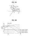
- FIGS. 3A and 3B are diagrams for explaining the operation of the conversion unit shown in FIG. 2 .
- the conversion unit 161 performs image conversion processing based on for example the distance from a reference position in each of the first image and the second image and an angle formed by a straight line passing through the reference position and a reference axis including the reference position to generate a first converted image and second converted image in the two-dimensional space defined by the distance and the angle.
- the conversion unit 161 performs the image processing for converting points in each image to patterns of curves based on a distance ⁇ 0 from the reference position O to the closest point P 0 on a straight line L 0 passing through the points in the image and an angle ⁇ 0 formed by a straight line n 0 passing through the reference position O and the closest point P 0 and the reference axis including the reference position O and converting the linear components in the image to a plurality of patterns of overlapped curves to generate the first converted image and second converted image.
- the points are converted to curves in the ⁇ - ⁇ space as shown in FIG. 3B .
- the conversion processing is for converting the point P 1 (x 1 ,y 1 ) to a curve PL 1 (x 1 ⁇ cos ⁇ +y 1 ⁇ sin ⁇ ), converting the point P 2 (x 2 ,y 2 ) to a curve PL 2 (x 2 ⁇ cos ⁇ +y 2 ⁇ sin ⁇ ), and converting the point P 3 (x 3 ,y 3 ) to a curve PL 3 (x 3 ⁇ cos ⁇ +y 3 ⁇ sin ⁇ ).
- the patterns of these curves PL 1 , PL 2 , and PL 3 cross at a crossing point CP ( ⁇ 0 , ⁇ 0 ) in the ⁇ - ⁇ space.
- the cross point CP ( ⁇ 0 , ⁇ 0 ) corresponds to the linear component L 0 on the x-y plane.
- the linear component L 0 on the x-y plane corresponds to the crossing point CP of patterns PL 1 , PL 2 , and PL 3 in the ⁇ - ⁇ space.
- image conversion processing for digitalization is carried out. It can be decided according to the degree of overlapping of the patterns of curves in the ⁇ - ⁇ space of the processing result which linear component is dominant on the x-y plane before the conversion.
- the rotation and parallel movement of the image on this x-y plane correspond to parallel movements in the ⁇ direction and the ⁇ direction in the ⁇ - ⁇ space after the image conversion processing.
- FIGS. 4A to 4F are diagrams for explaining the operation of the conversion unit shown in FIG. 2 .
- FIG. 4A is a diagram of a sample image va 1
- FIG. 4B is a diagram of an image va 2 obtained by rotating the image va 1 shown in FIG. 4A by exactly a predetermined angle ⁇
- FIG. 4C is a diagram of an image va 3 obtained by moving the image va 2 shown in FIG. 4B in parallel.
- the x-axis is plotted on the ordinate
- the y-axis is plotted on the abscissa.
- FIG. 4D is a diagram of an image hva 1 obtained by applying image conversion processing to the image va 1 shown in FIG.
- FIG. 4A and FIG. 4E is a diagram of an image hva 2 obtained by applying image conversion processing to the image va 2 shown in FIG. 4B .
- FIG. 4F is a diagram of an image hva 3 obtained by applying image conversion processing to the image va 3 shown in FIG. 4C .
- a ⁇ -axis is plotted on the ordinate, and a ⁇ -axis is plotted on the abscissa.
- the conversion unit 161 applies image conversion processing as shown in for example FIG. 4A to the image va 1 including the straight lines La 1 and La 2 , it generates an image hva 1 including the two points by the overlapping of the curve patterns in the image indicating the ⁇ - ⁇ space as shown in FIG. 4D .
- the conversion unit 161 applies image conversion processing as shown in FIG. 4B to the image va 2 obtained by rotating the image va 1 by exactly a predetermined angle ⁇ , it generates an image hva 2 shown in FIG. 4E .
- This image hva 2 is moved in parallel in the ⁇ direction by exactly an amount in accordance with the rotation angle ⁇ in the image indicating the ⁇ - ⁇ space in comparison with the image hva 1 shown in FIG. 4D .
- the conversion unit 161 applies image conversion processing as shown in FIG. 4C to an image va 3 obtained by moving the image va 2 in parallel by exactly a predetermined amount, it generates an image hva 3 shown in FIG. 4F .
- This image hva 3 moves in parallel in the ⁇ direction by exactly an amount in accordance with the amount of parallel movement in the image indicating the ⁇ - ⁇ space in comparison with the image hva 2 shown in FIG. 4E . From the above characteristic features, by calculating the degree of correlation by detecting the amount of parallel movement between images after the image conversion processing, it is possible to perform the matching considering the rotation angle and parallel movement of the image before the image conversion processing.
- FIGS. 5A to 5F are diagrams for explaining the operation of the conversion unit shown in FIG. 2 .
- the conversion unit 161 performs the image conversion processing on the registered image AIM shown in for example FIG. 5A , generates the image S 1611 shown in FIG. 5C , performs the image conversion processing on the match image RIM shown in FIG. 5B , and generates the image S 1612 .
- Values in accordance with the degrees of overlapping of patterns of curves are set in pixels in the images S 1611 and S 1612 .
- the higher the degree of overlapping of patterns of curves the whiter the displayed image.
- the matching unit 164 performs the matching processing based on this degree of overlapping of curve patterns, so performs the matching processing based on the linear components in the original x-y space.
- the extraction unit 162 extracts a region having a degree of overlapping of patterns of curves in one converted image more than a threshold value set in advance for each of the first converted image and second converted image.
- the extraction unit 162 extracts a region having a degree of overlapping of patterns of curves in one converted image more than a threshold value set in advance based on the signal S 1611 of the first converted image shown in FIG. 5C , generates the image signal S 1621 shown in FIG. 5E , and outputs the same to the correlation value generation unit 163 .
- the extraction unit 162 extracts a region having a degree of overlapping of patterns of curves in one converted image more than a threshold value set in advance based on the signal S 1612 of the second converted image shown in FIG. 5D , generates the image signal S 1622 shown in FIG. 5F , and outputs the same to the correlation value generation unit 163 .
- a noise component different from the linear component in the x-y space of for example the registered image AIM and the match image RIM for example, a point component, is eliminated.
- the extraction unit 162 makes the extraction processing unit 14 for performing the dedicated extraction processing (also referred to as the masking processing) in terms of for example hardware execute the extraction processing (masking processing) as the above extraction processing.
- the correlation value generation unit 163 performs the matching processing of the first image and second image based on results of the correlation processing at a plurality of different relative locations in a first direction and a second direction orthogonal to the first direction based on the signals S 1621 and S 1622 of the first converted image and the second converted image.
- the first direction and the second direction indicate the x-axis direction and the y-axis direction (or the ⁇ -axis direction and the ⁇ -axis direction) in the converted images.
- the correlation value generation unit 163 generates a correlation value based on the degree of overlapping of patterns in the first converted image and the second converted image and coincidence/incoincidence of patterns in the first converted image and second converted image based on the signals S 1621 and S 1622 of the first and second converted images and outputs the generated correlation value as a signal S 163 to the matching unit 164 .
- FIG. 6 is a functional block diagram of a concrete example of the correlation value generation unit 163 shown in FIG. 2 .
- the correlation value generation unit 163 has a correlation unit 1631 and a correlation value detection unit 1632 .
- the correlation unit 1631 performs the correlation processing using for example a phase limitation filter based on the signals S 1621 and S 1622 and outputs the processing result as a signal S 1631 to the correlation value detection unit 1632 .
- the correlation unit 1631 for example as shown in FIG. 6 , has Fourier transform units 16311 and 16312 , a combining unit 16313 , a phase extraction unit 16314 , and an inverse Fourier transform unit 16315 .
- the Fourier transform unit 16311 applies a Fourier transform to the signal S 1621 as shown in equation (2) in a case of for example an image pA(m,n) of M ⁇ N pixels, generates Fourier image data X(u,v), and outputs the same as a signal S 16311 to the combining unit 16313 .
- the Fourier transform unit 16312 applies the Fourier transform as shown in equation (3) to the signal S 1622 in a case of for example an image pB(m,n) of M ⁇ N pixels, generates Fourier image data Y(u,v), and outputs the same as a signal S 16312 to the combining unit 16313 .
- the Fourier image data X(u,v) is comprised of an amplitude spectrum C(u,v) and a phase spectrum ⁇ (u,v) as shown in equation (2), while the Fourier transform image data Y(u,v) is comprised of an amplitude spectrum D(u,v) and a phase spectrum ⁇ (u,v) as shown in equation (3).
- the combining unit 16313 combines the data X(u,v) and Y(u,v) generated at the Fourier transform units 16311 and 16312 and finds the correlation. For example, the combining unit 16313 generates X(u,v) ⁇ Y*(u,v) and outputs the same to the phase extraction unit 16314 .
- Y*(u,v) is a complex conjugate of Y(u,v).
- phase information is not limited to the above format.
- X ′( u,v ) e j ⁇ (u,v) (4)
- Y ′( u,v ) e j ⁇ (u,v) (5)
- the inverse Fourier transform unit 16315 performs the inverse Fourier transform processing based on the signal Z(u,v) of only the phase information output from the phase extraction unit 16314 to generate a correlation strength image.
- the inverse Fourier transform unit 16315 performs the inverse Fourier transform processing based on the signal Z(u,v) as shown in equation (7), generates the correlation strength image G(p,q), and outputs the same as the signal S 1631 to the correlation value detection unit 1632 .
- the correlation value detection unit 1632 detects a correlation value based on for example the peak strength in the correlation strength image G(p,q) based on the signal S 1631 output from the correlation unit 1631 and outputs the detected correlation value as the signal S 163 to the matching unit 164 .
- the correlation value detection unit 1632 defines the largest peak strength in the correlation strength image G(p,q) as the correlation value.
- FIGS. 7A to 7C are diagrams for explaining a correlation value of the correlation strength image G(p,q).
- FIGS. 7A and 7B are diagrams showing signals S 1621 and S 1622 of the converted images; and
- FIG. 7C is a diagram of the strength peak of the correlation strength image G(p,q).
- FIG. 8 is a diagram for explaining the correlation strength image G(p,q).
- the correlation value generation unit 163 performs correlation processing based on the images S 1621 and S 1622 as shown in for example FIGS. 7A and 7B , generates the correlation strength image G(p,q) as shown in FIG. 7C , and outputs the same as the signal S 1631 .
- FIG. 7A and 7B are diagrams showing signals S 1621 and S 1622 of the converted images
- FIG. 7C is a diagram of the strength peak of the correlation strength image G(p,q).
- FIG. 8 is a diagram for explaining the correlation strength image G(p,q).
- the z-axis indicates the correlation strength at the point (p,q).
- the correlation value detection unit 1632 outputs the correlation strength of the peak PP having the largest correlation strength as the correlation value signal S 163 to the matching unit 164 .
- the correlation strength image S 1631 is set so that the peak PP having the large correlation strength is formed at the image center position O of the correlation strength image S 1631 as shown in FIG. 8 .
- the correlation strength image S 1631 is set so that the peak PP is formed offset by exactly an amount in accordance with the rotation offset or parallel movement offset from the image center position O thereof.
- the correlation strength image is generated by the above correlation processing, even when there is rotation offset or parallel movement offset between the images S 1621 and S 1622 , the correlation peak can be found as the correlation value based on the correlation strength image.
- the matching unit 164 matches the registered image AIM and the match image RIM based on the signal S 163 indicating the correlation value output from the correlation value generation unit 163 .
- the matching unit 164 decides that a registered image AIM and the match image RIM coincide, while when the correlation value is less than the threshold value, it decides that they do not coincide.
- the CPU 16 makes the operation processing unit 17 perform predetermined processing such as unlocking of an electronic lock in accordance with the matching result of the matching unit 164 .
- FIG. 9 is a flow chart for explaining the operation of the image matching system shown in FIG. 1 .
- the operation of the image matching system 1 will be explained focusing on the operation of the CPU 16 by referring to FIGS. 3A and 3B , FIGS. 5A to 5F , and FIGS. 7A to 7C to FIG. 9 .
- the registered image AIM is input from the image input portion 11 in advance and stored in the memory 12 .
- the match image RIM is input from the image input portion 11 and stored in the memory 12 .
- the conversion unit 161 performs the image processing for converting points in the image to patterns of curves PL based on a distance ⁇ 0 from a reference position O to the closest point P 0 on the straight line L 0 passing through the point in the image and the angle ⁇ formed by the straight line n 0 passing through the reference position O and the closest point P 0 and the x-axis as the reference axis including the reference position O as shown in FIG. 3A based on for example the match image RIM shown in FIG. 5B and converting the linear component L in the image to patterns of a plurality of overlapped curves PL and generates the signal S 1612 as the converted image on the ⁇ - ⁇ space as shown in for example FIG. 5D .
- the extraction unit 162 performs the extraction processing (masking processing) for a region having the degree of overlapping of patterns of curves in one converted image more than the threshold value set in advance based on the converted image S 1612 .
- a value in accordance with the degree of overlapping of patterns of curves is set.
- the extraction unit 162 extracts a region having a degree of overlapping of patterns of curves in the converted image S 1612 shown in FIG. 5F more than the threshold value set in advance, generates the image S 1622 shown in for example FIG. 5E , and outputs the same to the correlation value generation unit 163 .
- the CPU 16 reads out a registered image AIM stored in the memory 12 .
- the conversion unit 161 performs the image processing for converting points in the image to patterns of curves PL based on the distance ⁇ 0 from the reference position O to the closest point P 0 on the straight line L 0 passing through the points in the image and the angle ⁇ formed by the straight line n 0 passing through the reference position O and the closest point P 0 and the x-axis as the reference axis including the reference position O as shown in FIG. 3A based on for example the registered image AIM shown in FIG. 5A and converting the linear components L in the image to patterns of a plurality of overlapped curves PL and generates the signal S 1611 as the converted image on the ⁇ - ⁇ space as shown in for example FIG. 5C .
- Steps ST 1 to ST 5 correspond to the first step of performing the image conversion processing based on the distance from the reference positions in each of the first image and the second image and the angle formed by the straight line passing through the reference position and the reference axis including the reference position and generating the first converted image and the second converted image in the two-dimensional space defined by the distance and the angle according to the present invention.
- the extraction unit 162 performs the extraction processing (masking processing) for a region having a degree of overlapping of patterns of curves in one converted image more than the threshold value set in advance based on the converted image S 1611 .
- the extraction unit 162 extracts a region having a degree of overlapping of patterns of curves in the converted image S 1611 shown in FIG. 5C more than the threshold value set in advance, generates the image S 1621 shown in for example FIG. 5E , and outputs the same to the correlation value generation unit 163 .
- the correlation value generation unit 163 generates the correlation value of the registered image AIM and the match image RIM based on the degree of overlapping of patterns in the converted image S 1621 and the converted image S 1622 and coincidence/incoincidence of the patterns in the converted image S 1621 and the converted image S 1622 .
- the Fourier transform units 16311 and 16312 of the correlation unit 1631 perform the Fourier transform processings as shown in for example equations (2) and (3) for the converted images S 1621 and S 1622 and outputs the processing results as signals S 16311 and S 16312 to the combining unit 16313 .
- steps ST 1 to ST 7 need not be in the above sequence either.
- the conversion unit 161 performs the conversion processing for the registered image AIM and the match image RIM, it is also possible to perform the extraction processing (masking processing) by the extraction unit 162 for the converted images.
- the combining unit 16313 performs the combining processing as mentioned above based on the signals S 16311 and S 16312 and outputs the processing result as the signal S 16313 to the phase extraction unit 16314 .
- the phase extraction unit 16314 extracts only the phase component based on the signal S 16313 and outputs the same as the signal S 16314 to the inverse Fourier transform unit 16315 .
- the inverse Fourier transform unit 16315 performs the inverse Fourier transform processing based on the signal S 16314 and outputs the same as the signal S 1631 as shown in for example FIG. 7C to the correlation value detection unit 1632 .
- the magnitude of the correlation strength peak of this correlation strength image S 1631 indicates the degree of the correlation between the converted images after the image conversion. For example, when there is parallel movement offset between the converted images, the location of the correlation strength peak of the correlation strength image S 1631 is offset from the center position O by exactly the amount corresponding to the amount of parallel movement offset between converted images, but does not exert an influence upon the correlation strength.
- the correlation value detection unit 1632 defines the strength of the correlation strength peak PP as the correlation value and outputs the signal S 163 to the matching unit 164 .
- the matching unit 164 performs the matching based on the signal S 163 indicating tye correlation value from the correlation value detection unit 1632 .
- the matching unit 164 decides whether or not the correlation value is larger than the threshold value determined in advance and, when deciding the correlation value is larger, outputs a matching result signal S 164 indicating that the registered image AIM and the match image RIM coincide (ST 13 ).
- the matching unit 164 when deciding that the correlation value is smaller than the threshold value determined in advance, outputs the matching result signal S 164 indicating that the registered image AIM and the match image RIM do not coincide (ST 14 ) and ends the series of processings.
- Steps ST 7 to ST 12 correspond to the second step of performing the matching processing of the first image and second image based on the results of correlation processing at a plurality of different relative locations in the first direction and the second direction orthogonal to the first direction in the first converted image and the second converted image generated in the first step according to the present invention.
- the conversion unit 161 for performing the image conversion processing based on the distance from a reference position in each of the first image and second image and the angle formed by the straight line passing through the reference position and the reference axis including the reference position and generating the first converted image and the second converted image in the two-dimensional space defined by the distances and the angle in more detail, the conversion unit 161 for performing the image processing based on the registered image AIM and the match image RIM for converting points in the image to patterns of curves PL based on the distance ⁇ from the reference position O to the closest point P 0 of the straight line L passing through the point in the image and the angle ⁇ formed by the straight line no passing through the reference position O and the closest point P 0 and the x-axis as the reference axis including the reference position O and converting the linear components in the image to patterns of a plurality of overlapped curves PL and generating the converted images S 1611 and S 1612 , the correlation value generation unit 163 for performing
- the matching unit 164 performs the matching based on the degree of overlapping in patterns in the converted image S 1611 and the converted image S 1612 generated by the conversion unit 161 and coincidence/incoincidence of the patterns in the converted image S 1611 and the converted image S 1612 , therefore can match images with a high precision. Further, even in the case where there is parallel movement offset or rotation angle offset between the registered image AIM and the match image RIM, the parallel movement offset and the rotation angle offset appear as parallel movement offset between the converted images S 1611 and S 1612 after the image conversion processing according to the present invention. In the correlation processing according to the present invention, even in the case where there is parallel movement offset between the converted images S 1611 and S 1612 , the correlation value can be generated, and matching can be carried out with a simple processing.
- the matching processing is carried out in units of pixels, but in the image matching according to the present embodiment, it is not necessary to perform such correction processing, so the matching processing can be carried out with a low load and at a high speed.
- FIG. 10 is a functional block diagram of the image matching system according to a second embodiment of the present invention.
- An image matching system 1 a according to the present embodiment performs Huff conversion processing based on the registered image AIM and the match image RIM, corrects the parallel movement offset of the converted images, generates the similarity as the correlation value between the converted images after the position correction, and performs the matching processing between the registered image AIM and the match image RIM based on the similarity.
- the image processing apparatus 1 a has the same components as those of the functional block diagram shown in FIG. 1 in terms of for example hardware, so the explanation will be omitted.
- the image processing apparatus 1 a in terms of software, for example as shown in FIG. 10 , realizes the conversion unit 161 , the extraction unit 162 , a correlation value generation unit 163 a , a position correction unit 170 , and a matching unit 164 a by executing the program PRG in the memory 12 by the CPU 16 .
- the difference between the first embodiment and the second embodiment resides in the point that the position correction unit 170 is added, the point that the correlation value generation unit 163 a outputs the signal S 1631 used for the position correction processing, and the point that the function of the matching unit 164 a is different.
- the components having the same functions between the first embodiment and the second embodiment are assigned the same notations, and explanations will be omitted.
- the correlation value generation unit 163 a performs the correlation processing based on the images S 1621 and S 1622 as shown in for example FIGS. 7A and 7B , generates the correlation strength image G(p,q) as shown in FIG. 7C , and outputs the same as the signal S 1631 .
- the position correction unit 170 performs the position correction processing based on the signal S 1631 output from the correlation value generation unit 163 a and the signals S 1621 and S 1622 output from the extraction unit 162 , that is, based on the patterns in the first converted image and the second converted image, and outputs the results of the position correction processing as a signal S 1701 and a signal S 1702 to the matching unit 164 a.
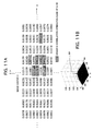
- FIGS. 11A and 11B are diagrams for explaining the operation of the position correction unit shown in FIG. 10 .
- the numerical values indicate the correlation peak strengths of the correlated image data on the X-Y plane of the correlated image data.
- the correlation peak strength also referred to as the correlation strength
- the correlation strength has the small value as shown in FIGS. 11A and 11B .
- the position correction unit 170 specifies N correlation values and correlation peak positions having higher correlation strengths, i.e., in the present embodiment, eight correlation values and correlation peak positions, as the candidates of positional relationships in the two dimensions between the registered image AIM and the match image RIM as shown in for example FIG. 11A .
- the position correction unit 170 performs the position correction by performing a plurality of position correction processings according to need, for example, parallel movement, so that the patterns between the registered image AIM and the match image RIM substantially coincide based on a plurality of correlation values and the correlation peak positions corresponding to them.
- the matching unit 164 a generates the correlation values based on patterns in two converted images and performs the matching processing between the registered image AIM and the match image RIM based on the generated correlation values and a threshold value set in advance. Further, the matching unit 164 a performs the matching processing based on the sum of correlation values corresponding to different positions and the threshold value set in advance based on results of a plurality of position correction processings.
- the matching unit 164 a has a similarity generation unit 1641 , a decision unit 1642 , and a summation unit 1643 .
- FIGS. 12A and 12B are diagrams for explaining the operation of the similarity generation unit 1641 .
- the similarity generation unit 1641 performs the comparison processing for each of for example a plurality of different positional relationships in the first converted image and the second converted image and generates the similarities as correlation values based on the results of the comparison processing.
- the similarity generation unit 1641 performs the comparison processing for each of a plurality of different positional relationships in two images based on the signal S 1701 and the signal S 1702 as shown in for example FIGS. 12A and 12B and generates similarities as correlation values based on the results of the comparison processing.
- the similarity generation unit 1641 calculates for example the similarity Sim by equation (8) and outputs the calculation result as S 1641 .
- FIGS. 13A to 13C are diagrams for explaining the operation of the similarity generation unit shown in FIG. 10 .
- the similarity generation unit 1641 When generating the similarity of two images including the linear components (also referred to as the linear shapes) shown in for example FIGS. 13A and 13B , the similarity generation unit 1641 generates similarity in accordance with the number of the cross points CP of the two images as shown in FIG. 13C .
- the linear component are indicated by black pixels having a bit value ‘1’, and the other components are indicated by white pixels having a bit value ‘0’.
- the summation unit 1643 sums up the similarities Sim based on the signal S 1641 and outputs the summation result as a signal S 1643 to the decision unit 1642 .
- the decision unit 1642 matches the registered image AIM and the match image RIM based on the signal S 1641 indicating similarity generated by the similarity generation unit 1641 . For example, when the similarity is larger than the predetermined value, the decision unit 1642 decides that the registered image AIM and the match image RIM coincide. Further, the decision unit 1642 decides that the registered image AIM and the match image RIM coincide when the signal S 1643 of the summed up value of the similarities Sim from the summation unit 1643 is larger than a predetermined threshold value.
- FIG. 14 is a flow chart for explaining the operation of the image matching system according to the second embodiment shown in FIG. 10 .
- An explanation will be given of the operation of the image matching system focusing on the operation of the CPU by referring to FIG. 14 .
- the same notations are assigned to the same operations as those in the first embodiment and the explanation is omitted. Only the differences will be explained.
- the processings of steps ST 1 to ST 10 are the same as those of the first embodiment, so the explanations will be omitted.
- Step ST 2 and step ST 6 correspond to the fourth step and fourth routine according to the present invention.
- the position correction unit 170 performs the position correction processing based on the correlation strength image G(p,q) output as the signal S 1631 from the correlation value generation unit 163 a and the signals S 1621 and S 1622 output from the extraction unit 162 , that is, the patterns in the first converted image and the second converted image, and outputs the results of the position correction processing as the signal S 1701 and the signal S 1702 to the matching unit 164 a .
- Step ST 111 corresponds to the third step and third routine according to the present invention.
- the position correction unit 170 based on the signal S 1631 , specifies (selects) for example eight correlation values and correlation peak positions in the present embodiment as shown in FIG. 11A as candidates of the positional relationships in the two-dimensional space between the registered image AIM and the match image RIM, for example, the higher N candidates Pi (P 0 , P 1 , . . . , PN ⁇ 1).
- the summation unit 1643 initializes the variables for the summation. For example, it initializes the variables i to 0 and initializes the summed up value S to 0.
- the position correction unit 170 performs the position correction processing of the registered image AIM and the match image RIM based on for example each candidate (coordinate) Pi and the amount of offset from the center of the correlated image data corresponding to that.
- the similarity Sim(i) is calculated by the similarity generation unit 1641 and output to the summation unit 1643 and the decision unit 1642 .
- the matching unit 1642 compares the summed up value S and the second threshold value th 2 set in advance. When the summed up value S is smaller than the second threshold value th 2 , it compares the variable i and the value N ⁇ 1 (ST 118 ).
- variable i When the variable i does not coincide with N ⁇ 1, it adds 1 to the variable i (ST 119 ) and returns to the processing of step ST 113 .
- step ST 118 when the variable i coincides with N ⁇ 1, it is decided that the images do not coincide (ST 120 ).
- step ST 115 when the similarity Sim(i) is more than the first threshold value, the matching unit 1642 decides that the images coincide.
- step ST 117 when the summed up value S is more than the second threshold value th 2 , the matching unit 1642 decides that the images coincide (ST 121 ).
- the operation processing unit 17 performs processing such as unlocking of the electronic lock.
- the position correction unit 170 generates a plurality of correlation values indicating the correction positions and performs a plurality of position correction processings of the registered image AIM and the match image RIM based on generated plurality of correlation values, and the decision unit 1642 performs the matching processing based on the summed up value of the similarities as the correlation value in accordance with the patterns in the converted images. Therefore, for example, even in a case where the correlation between two image data to be compared is small, by summing up the similarity calculated for each of the positional relationships of a plurality of candidates, the matching can be carried out with a high precision in comparison with the case where the matching is carried out solely by the similarity.
- the matching processing can be carried out at a high speed.
- the similarity generation unit calculated the similarity by equation (8), but the invention is not limited to this format.
- the similarity generation unit may perform the processing for calculating similarity suitable for correlation of the linear components (linear patterns).
- first threshold value th 1 and the second threshold value th 2 were fixed values, but the present invention is not limited to this format. For example, matching of a higher precision can be carried out by making each of the threshold values variable according to the image pattern.
- the image matching system 1 b stores a plurality of images as the registered images or the matching images, performs the correlation processing between converted images having a low resolution (that is, having a small image size) at first when performing the matching processing of the images, and performs the matching processing according to the first embodiment or the second embodiment between images having normal resolutions (that is, normal image size) based on the correlation processing results.
- the image matching system 1 b performs for example image conversion processing based on the distance from the reference position in each of the first image and the second image and the angle formed by the straight line passing through the reference position and the reference axis including the reference position, generates a third converted image and a fourth converted image having a lower resolution than that of the first converted image and the second converted image in the two-dimensional space defined by the distance and angle, decides whether or not the high resolution (normal resolution) correlation processing and the matching processing are to be performed based on the results of the correlation processing at a plurality of different relative locations in the first direction and the second direction orthogonal to the first direction in the generated third converted image and fourth converted image, suspends the matching processing and performs the matching processing for the other image when the correlation value is lower than the predetermined threshold value, and continuously performs the high resolution matching processing for only an image having a resolution higher than the threshold value.
- the functional block diagram of the image matching system 1 b according to the present embodiment has the same components as those of the image matching system according
- FIG. 15 is a diagram for explaining the operation of an image matching system according to a third embodiment of the present invention. It is determined according to the size of the ⁇ - ⁇ plane (also referred to as a parameter space) generated by the image conversion processing according to the present embodiment to which extent the straight line on the x-y plane of the image is finely sectioned as a parameter. The larger the size of the parameter space, the finer the straight line can be sectioned, so the higher the resolution by that amount.
- the conversion unit 161 performs the image conversion processing with a parameter space size of a high resolution (for example, 180 ⁇ 180 pixels) based on an image vb 1 including the straight line having a rotation angle offset shown in FIG.
- the conversion unit 161 generates an image vb 3 indicating the result of the image conversion processing with a parameter space size of a low resolution (for example 30 ⁇ 30 pixels) based on the image vb 1 including the straight lines having the rotation angle offset shown in FIG. 15A .
- a parameter space size of a low resolution for example 30 ⁇ 30 pixels
- each of the straight lines having an angle offset before the image conversion are classified to other ⁇ parameters ( ⁇ 1 , ⁇ 2 ), but in contrast, in the image vb 3 of low resolution shown in FIG. 15C , they are classified as the same ⁇ parameter ( ⁇ 3 ).
- the processing speed of the matching processing between images after the image conversion processing according to the present invention depends upon the processing speed of the parameter space. In more detail, for example, the larger the size of the parameter space, that is, the higher the resolution, the longer the processing time and the larger the processing load.
- the smaller the size of the parameter space that is, the lower the resolution, the shorter the processing time and the smaller the processing load.
- the image matching system when the matching is carried out between the input match image RIM and a plurality of registered images AIM stored in the memory 12 , first, based on the result of calculation of the correlation value in the parameter space having a low resolution, by excluding an image having a low correlation value as the result of this from the coincidence candidates, the time taken for the entire matching processing is shortened.
- FIG. 16 is a flow chart for explaining the operation of the image matching system according to the third embodiment of the present invention. Only the differences from the first embodiment and the second embodiment will be explained focusing on the operation of the CPU of the image matching system by referring to FIG. 16 .
- a plurality of registered images AIM are input from the image input portion 11 in advance and stored in the memory 12 .
- a match image RIM is input from the image input portion 11 and stored in the memory 12 .
- image conversion processing is performed based on the distance from a reference position in each of the first image and the second image and the angle formed by the straight line passing through the reference position and the reference axis including the reference position, a third converted image and a fourth converted image having a lower resolution than that of the first converted image and the second converted image in a two-dimensional space defined by the distance and angle are generated, and it is decided whether or not high resolution conversion processing and matching processing are to be performed based on the results of the correlation processing at a plurality of different relative locations in the first direction and the second direction orthogonal to the first direction in the generated third converted image and fourth converted image.
- a parameter space of a low resolution is set.
- the conversion unit 161 performs image processing of converting points in the image to pattern of curves PL based on the distance ⁇ 0 from the reference position O to the closest point P 0 on the straight line L 0 passing through the points in the image and the angle ⁇ formed by the straight line n 0 passing through the reference position O and the closest point P 0 and the x-axis as the reference axis including the reference position O as shown in FIG. 3A based on for example the match image RIM and converting the linear components L in the image to patterns of a plurality of overlapped curves PL and generates the signal S 1612 as the converted image in the ⁇ - ⁇ space.
- the extraction unit 162 performs the extraction processing (masking processing) for a region having a degree of overlapping of patterns of curves in one converted image more than the threshold value set in advance based on the converted image S 1612 .
- the extraction processing masking processing
- a value in accordance with the degree of overlapping of patterns of curves is set.
- the extraction unit 162 extracts a region having a degree of overlapping of patterns of curves in the converted image S 1612 more than a threshold value set in advance, generates the image S 1622 , and outputs the same to the correlation value generation unit 163 .
- the CPU 16 reads out a registered image AIM stored in the memory 12 .
- the conversion unit 161 performs image processing for converting points in the image to patterns of the curves PL based on the distance ⁇ 0 from the reference position O to the closest point P 0 on the straight line L 0 passing through the points in the image and the angle ⁇ formed by the straight line n 0 passing through the reference position O and the closest point P 0 and the x-axis as the reference axis including the reference position O as shown in FIG. 3A based on for example the registered image AIM and converting the linear components L in the image to patterns of a plurality of overlapped curves PL and generates the signal S 1611 as the converted image in the ⁇ - ⁇ space.
- the extraction unit 162 performs the extraction processing (masking processing) for a region having a degree of overlapping of patterns of curves in one converted image more than a threshold value set in advance based on the converted image S 1611 .
- the extraction unit 162 extracts a region having a degree of overlapping of patterns of curves in the converted image S 1611 more than the threshold value set in advance, generates the image S 1621 , and outputs the same to the correlation value generation unit 163 .
- the correlation value generation unit 163 generates correlation values between the registered image AIM and the match image RIM based on the degree of overlapping of patterns in the converted image S 1621 and the converted image S 1622 and coincidence/incoincidence of patterns in the converted image S 1621 and the converted image S 1622 .
- the Fourier transform units 16311 and 16312 of the correlation unit 1631 perform Fourier transform processings for the converted images S 1621 and 1622 as shown in for example equations (2) and (3) and outputs the processing results as signals S 16311 and S 16312 to the combining unit 16313 .
- steps ST 201 to ST 208 need not be in the above sequence.
- the combining unit 16313 performs the combining processing as mentioned above based on the signals S 16311 and S 16312 and outputs the processing result as the signal S 16313 to the phase extraction unit 16314 .
- the phase extraction unit 16314 extracts only the phase component based on the signal S 16313 and outputs the same as the signal S 16314 to the inverse Fourier transform unit 16315 .
- the inverse Fourier transform unit 16315 performs the inverse Fourier transform processing based on the signal S 16314 and outputs the same as the signal S 1631 to the correlation value detection unit 1632 as shown in for example FIG. 7C .
- the magnitude of the correlation strength peak of this correlation strength image S 1631 indicates the degree of the correlation between the converted images after the image conversion. For example, when there is parallel movement offset between the converted images, the position of the correlation strength peak of the correlation strength image S 1631 is offset from the center position O by exactly the amount corresponding to the amount of parallel movement offset between converted images, but does not exert an influence upon the correlation strength.
- the correlation value detection unit 1632 defines the strength of the correlation strength peak PP as the correlation value and outputs the signal S 163 to the matching unit 164 .
- the matching unit 164 performs the matching based on the signal S 163 indicating the correlation value from the correlation value detection unit 1632 .
- the matching unit 164 decides whether or not the correlation value is larger than a threshold value determined in advance and, when deciding that the correlation value is smaller, suspends the matching of the registered image AIM, reads out another registered image AIM in the memory 12 , and returns to the processing of step 206 .
- the matching unit 164 decides that the registered image AIM is a coincidence candidate of the match image RIM and sets a parameter space of a high resolution.
- step ST 203 to step ST 212 are carried out for the image of the high resolution parameter space (ST 216 to ST 224 ).
- the matching unit 164 performs the matching based on the signal S 163 indicating the correlation value from the correlation value detection unit 1632 .
- the matching unit 164 decides whether or not the correlation value is larger than the threshold value determined in advance. When deciding that the correlation value is larger, it outputs the matching result signal S 164 indicating that the registered image AIM and the match image RIM coincide (ST 226 ).
- the matching unit 164 when deciding that the correlation value is smaller than the threshold value determined in advance at step ST 225 , the matching unit 164 outputs the matching result signal S 164 indicating that the registered image AIM and the match image RIM do not coincide (ST 227 ), reads out another registered image AIM in the memory 12 (ST 228 ), sets the low resolution (ST 229 ), and returns to the processing of step 206 .
- the image conversion processing is performed based on the distance from the reference position in each of the first image and the second image and the angle formed by the straight line passing through the reference position and the reference axis including the reference position, the third converted image and the fourth converted image having a lower resolution than that of the first converted image and the second converted image in the two-dimensional space defined by the distance and angle are generated, and it is decided whether or not the high resolution conversion processing and matching processing are to be performed based on the results of the correlation processing at a plurality of different relative locations in the first direction and the second direction orthogonal to the first direction in the generated third converted image and fourth converted image.
- the correlation value is lower, the matching of the images is suspended and the matching processing of another image is carried out, so the processing time of the overall matching processing can be shortened. Further, the low resolution image matching processing is first carried out, so the processing load is reduced.
- the present invention is not limited to the present embodiment. Any suitable modification is possible. For example, by performing the low resolution image conversion processing for the registered image AIM in advance and performing the matching processing between these images, the matching time can be shortened more.
- the present invention can also be applied to security related applications for matching two images of blood vessel images, fingerprint images, still images, and moving images based on the linear components in the images.
- an image matching method capable of matching images with a high precision and a program and an image matching system for the same can be provided.
Abstract
Description
ρ=x·cos θ+y·sin θ (1)
X′(u,v)=e jθ(u,v) (4)
Y′(u,v)=e jθ(u,v) (5)
Z(u,v)=X′(u,v)(Y′(u,v))*=e j(θ(u,v)−φ(u,v)) (6)
Claims (12)
Priority Applications (1)
| Application Number | Priority Date | Filing Date | Title |
|---|---|---|---|
| US12/656,722 US7860279B2 (en) | 2003-10-07 | 2010-02-16 | Image matching method, program, and image matching system |
Applications Claiming Priority (2)
| Application Number | Priority Date | Filing Date | Title |
|---|---|---|---|
| JP2003-348293 | 2003-10-07 | ||
| JP2003348293A JP4345426B2 (en) | 2003-10-07 | 2003-10-07 | Image collation method, program, and image collation apparatus |
Related Child Applications (1)
| Application Number | Title | Priority Date | Filing Date |
|---|---|---|---|
| US12/656,722 Continuation US7860279B2 (en) | 2003-10-07 | 2010-02-16 | Image matching method, program, and image matching system |
Publications (2)
| Publication Number | Publication Date |
|---|---|
| US20050111738A1 US20050111738A1 (en) | 2005-05-26 |
| US7720307B2 true US7720307B2 (en) | 2010-05-18 |
Family
ID=34309206
Family Applications (2)
| Application Number | Title | Priority Date | Filing Date |
|---|---|---|---|
| US10/949,211 Expired - Fee Related US7720307B2 (en) | 2003-10-07 | 2004-09-27 | Image matching method, program, and image matching system |
| US12/656,722 Expired - Fee Related US7860279B2 (en) | 2003-10-07 | 2010-02-16 | Image matching method, program, and image matching system |
Family Applications After (1)
| Application Number | Title | Priority Date | Filing Date |
|---|---|---|---|
| US12/656,722 Expired - Fee Related US7860279B2 (en) | 2003-10-07 | 2010-02-16 | Image matching method, program, and image matching system |
Country Status (8)
| Country | Link |
|---|---|
| US (2) | US7720307B2 (en) |
| EP (2) | EP1876554B1 (en) |
| JP (1) | JP4345426B2 (en) |
| KR (1) | KR101038639B1 (en) |
| CN (3) | CN101149789A (en) |
| DE (1) | DE602004030495D1 (en) |
| HK (1) | HK1073372A1 (en) |
| TW (1) | TW200523818A (en) |
Cited By (17)
| Publication number | Priority date | Publication date | Assignee | Title |
|---|---|---|---|---|
| US20100322485A1 (en) * | 2009-06-18 | 2010-12-23 | Research In Motion Limited | Graphical authentication |
| US20110007271A1 (en) * | 2009-07-09 | 2011-01-13 | Canon Kabushiki Kaisha | Ophthalmologic imaging apparatus and ophthalmologic imaging method |
| US20120159594A1 (en) * | 2010-12-16 | 2012-06-21 | Research In Motion Limited | Adjusting the position of an endpoint reference for increasing security during device log-on |
| US8631487B2 (en) | 2010-12-16 | 2014-01-14 | Research In Motion Limited | Simple algebraic and multi-layer passwords |
| US8635676B2 (en) | 2010-12-16 | 2014-01-21 | Blackberry Limited | Visual or touchscreen password entry |
| US8650635B2 (en) | 2010-12-16 | 2014-02-11 | Blackberry Limited | Pressure sensitive multi-layer passwords |
| US8650624B2 (en) | 2010-12-16 | 2014-02-11 | Blackberry Limited | Obscuring visual login |
| US8661530B2 (en) | 2010-12-16 | 2014-02-25 | Blackberry Limited | Multi-layer orientation-changing password |
| US8769641B2 (en) | 2010-12-16 | 2014-07-01 | Blackberry Limited | Multi-layer multi-point or pathway-based passwords |
| US8769668B2 (en) | 2011-05-09 | 2014-07-01 | Blackberry Limited | Touchscreen password entry |
| US20140193768A1 (en) * | 2011-09-28 | 2014-07-10 | Telesystems Co., Ltd | Image processing apparatus and image processing method |
| US8863271B2 (en) | 2010-12-16 | 2014-10-14 | Blackberry Limited | Password entry using 3D image with spatial alignment |
| US8931083B2 (en) | 2010-12-16 | 2015-01-06 | Blackberry Limited | Multi-layer multi-point or randomized passwords |
| US9135426B2 (en) | 2010-12-16 | 2015-09-15 | Blackberry Limited | Password entry using moving images |
| US20150264046A1 (en) * | 2013-05-03 | 2015-09-17 | Morpho | Method for identifying/authenticating a person using the venous network thereof |
| US9223948B2 (en) | 2011-11-01 | 2015-12-29 | Blackberry Limited | Combined passcode and activity launch modifier |
| US9258123B2 (en) | 2010-12-16 | 2016-02-09 | Blackberry Limited | Multi-layered color-sensitive passwords |
Families Citing this family (34)
| Publication number | Priority date | Publication date | Assignee | Title |
|---|---|---|---|---|
| JP4428067B2 (en) * | 2004-01-28 | 2010-03-10 | ソニー株式会社 | Image collation apparatus, program, and image collation method |
| US8989349B2 (en) * | 2004-09-30 | 2015-03-24 | Accuray, Inc. | Dynamic tracking of moving targets |
| US7812986B2 (en) | 2005-08-23 | 2010-10-12 | Ricoh Co. Ltd. | System and methods for use of voice mail and email in a mixed media environment |
| US9171202B2 (en) | 2005-08-23 | 2015-10-27 | Ricoh Co., Ltd. | Data organization and access for mixed media document system |
| US9530050B1 (en) | 2007-07-11 | 2016-12-27 | Ricoh Co., Ltd. | Document annotation sharing |
| US9495385B2 (en) | 2004-10-01 | 2016-11-15 | Ricoh Co., Ltd. | Mixed media reality recognition using multiple specialized indexes |
| US8156115B1 (en) | 2007-07-11 | 2012-04-10 | Ricoh Co. Ltd. | Document-based networking with mixed media reality |
| US9373029B2 (en) | 2007-07-11 | 2016-06-21 | Ricoh Co., Ltd. | Invisible junction feature recognition for document security or annotation |
| US9384619B2 (en) | 2006-07-31 | 2016-07-05 | Ricoh Co., Ltd. | Searching media content for objects specified using identifiers |
| US9405751B2 (en) | 2005-08-23 | 2016-08-02 | Ricoh Co., Ltd. | Database for mixed media document system |
| US7702673B2 (en) | 2004-10-01 | 2010-04-20 | Ricoh Co., Ltd. | System and methods for creation and use of a mixed media environment |
| WO2007070051A1 (en) * | 2005-12-16 | 2007-06-21 | Thomson Licensing | Method, apparatus and system for color component registration |
| JP4038777B2 (en) | 2006-02-28 | 2008-01-30 | ソニー株式会社 | Registration device and authentication device |
| US20080021300A1 (en) * | 2006-06-29 | 2008-01-24 | Allison John W | Four-dimensional target modeling and radiation treatment |
| US8201076B2 (en) | 2006-07-31 | 2012-06-12 | Ricoh Co., Ltd. | Capturing symbolic information from documents upon printing |
| US9176984B2 (en) | 2006-07-31 | 2015-11-03 | Ricoh Co., Ltd | Mixed media reality retrieval of differentially-weighted links |
| US9063952B2 (en) * | 2006-07-31 | 2015-06-23 | Ricoh Co., Ltd. | Mixed media reality recognition with image tracking |
| US8489987B2 (en) | 2006-07-31 | 2013-07-16 | Ricoh Co., Ltd. | Monitoring and analyzing creation and usage of visual content using image and hotspot interaction |
| EP1912160B1 (en) * | 2006-10-11 | 2012-05-16 | Mitsubishi Electric R&D Centre Europe B.V. | Image descriptor for image recognition |
| JP5003092B2 (en) * | 2006-10-17 | 2012-08-15 | ソニー株式会社 | Registration device, verification device, authentication method, and authentication program |
| GB0700468D0 (en) * | 2007-01-10 | 2007-02-21 | Mitsubishi Electric Inf Tech | Improved image identification |
| JP2009140076A (en) * | 2007-12-04 | 2009-06-25 | Sony Corp | Authentication apparatus and authentication method |
| KR100889026B1 (en) * | 2008-07-22 | 2009-03-17 | 김정태 | Searching system using image |
| CN102165465B (en) * | 2008-09-23 | 2014-02-19 | 美国医软科技公司 | Methods for interactive labeling of tubular structures in medical imaging |
| TWI585596B (en) * | 2009-10-01 | 2017-06-01 | Alibaba Group Holding Ltd | How to implement image search and website server |
| US9058331B2 (en) | 2011-07-27 | 2015-06-16 | Ricoh Co., Ltd. | Generating a conversation in a social network based on visual search results |
| WO2013078404A1 (en) * | 2011-11-22 | 2013-05-30 | The Trustees Of Dartmouth College | Perceptual rating of digital image retouching |
| US10157306B2 (en) * | 2015-02-27 | 2018-12-18 | Idex Asa | Curve matching and prequalification |
| JP6333871B2 (en) * | 2016-02-25 | 2018-05-30 | ファナック株式会社 | Image processing apparatus for displaying an object detected from an input image |
| GB2555675B (en) * | 2016-08-05 | 2019-05-08 | Secr Defence | Method and apparatus for generating an enhanced digital image of a physical object or environment |
| CN108133492B (en) | 2016-12-01 | 2022-04-26 | 京东方科技集团股份有限公司 | Image matching method, device and system |
| CN107563293A (en) * | 2017-08-03 | 2018-01-09 | 广州智慧城市发展研究院 | A kind of new finger vena preprocess method and system |
| JPWO2020145004A1 (en) * | 2019-01-10 | 2021-10-28 | 日本電気株式会社 | Shooting guide device |
| CN113588667A (en) * | 2019-05-22 | 2021-11-02 | 合肥联宝信息技术有限公司 | Method and device for detecting object appearance |
Citations (18)
| Publication number | Priority date | Publication date | Assignee | Title |
|---|---|---|---|---|
| JPH04295973A (en) | 1991-03-25 | 1992-10-20 | Matsushita Electric Ind Co Ltd | Pattern curve applying method by hough transformation |
| US5430810A (en) * | 1990-11-20 | 1995-07-04 | Imra America, Inc. | Real time implementation of the hough transform |
| US5583956A (en) * | 1993-01-12 | 1996-12-10 | The Board Of Trustees Of The Leland Stanford Junior University | Estimation of skew angle in text image |
| JPH0954827A (en) | 1995-08-14 | 1997-02-25 | Nippon Telegr & Teleph Corp <Ntt> | High-speed image template matching method |
| JPH09282458A (en) | 1996-04-18 | 1997-10-31 | Glory Ltd | Image collating device |
| JPH09330414A (en) | 1996-06-12 | 1997-12-22 | Yoshihiko Nomura | Picture matching method and device therefor |
| JPH1021391A (en) | 1996-06-28 | 1998-01-23 | Glory Ltd | Method and device for collating picture |
| TW328576B (en) | 1996-07-16 | 1998-03-21 | Chen Bor Ning | Automatic seal-imprint comparing method and apparatus |
| JPH10162139A (en) | 1996-11-28 | 1998-06-19 | Nikon Corp | Image processor, and medium where image processing program is recorded |
| US6032167A (en) | 1997-04-30 | 2000-02-29 | Fujitsu Limited | Data processing circuit adapted for use in pattern matching |
| JP2001175864A (en) | 1999-12-21 | 2001-06-29 | Nec Corp | Device and method for image matching |
| US6301375B1 (en) | 1997-04-14 | 2001-10-09 | Bk Systems | Apparatus and method for identifying individuals through their subcutaneous vein patterns and integrated system using said apparatus and method |
| US20020028027A1 (en) * | 2000-09-07 | 2002-03-07 | Fuji Xerox Co., Ltd. | Image processing device, image processing method, and recording medium storing image processing program |
| US6408105B1 (en) * | 1998-05-12 | 2002-06-18 | Advantest Corporation | Method for detecting slope of image data utilizing hough-transform |
| US20020126901A1 (en) * | 2001-01-31 | 2002-09-12 | Gretag Imaging Trading Ag | Automatic image pattern detection |
| US6687421B1 (en) * | 2000-03-17 | 2004-02-03 | International Business Machines Corporation | Skew detection of text in a noisy digitized image |
| US20080232713A1 (en) * | 2004-06-18 | 2008-09-25 | Ken Iizuka | Image Matching Method, Image Matching Apparatus, and Program |
| JP4295973B2 (en) | 2002-11-08 | 2009-07-15 | 株式会社岡村製作所 | Chair transport |
Family Cites Families (9)
| Publication number | Priority date | Publication date | Assignee | Title |
|---|---|---|---|---|
| US5548667A (en) * | 1991-05-24 | 1996-08-20 | Sony Corporation | Image processing system and method thereof in which three dimensional shape is reproduced from two dimensional image data |
| US5812252A (en) * | 1995-01-31 | 1998-09-22 | Arete Associates | Fingerprint--Acquisition apparatus for access control; personal weapon and other systems controlled thereby |
| JP2776340B2 (en) * | 1995-11-08 | 1998-07-16 | 日本電気株式会社 | Fingerprint feature extraction device |
| US6373970B1 (en) * | 1998-12-29 | 2002-04-16 | General Electric Company | Image registration using fourier phase matching |
| KR100308456B1 (en) * | 1999-07-09 | 2001-11-02 | 오길록 | Texture description method and texture retrieval method in frequency space |
| KR100355404B1 (en) * | 1999-12-03 | 2002-10-11 | 삼성전자 주식회사 | Texture description method and texture retrieval method using Gabor filter in frequency domain |
| JP4128001B2 (en) * | 2001-11-19 | 2008-07-30 | グローリー株式会社 | Distortion image association method, apparatus, and program |
| JP4428067B2 (en) * | 2004-01-28 | 2010-03-10 | ソニー株式会社 | Image collation apparatus, program, and image collation method |
| JP4038777B2 (en) * | 2006-02-28 | 2008-01-30 | ソニー株式会社 | Registration device and authentication device |
-
2003
- 2003-10-07 JP JP2003348293A patent/JP4345426B2/en not_active Expired - Fee Related
-
2004
- 2004-09-27 US US10/949,211 patent/US7720307B2/en not_active Expired - Fee Related
- 2004-09-29 CN CNA2007101370487A patent/CN101149789A/en active Pending
- 2004-09-29 CN CNA2007101697535A patent/CN101174301A/en active Pending
- 2004-09-29 CN CNB2004101047590A patent/CN100362524C/en not_active Expired - Fee Related
- 2004-10-05 DE DE602004030495T patent/DE602004030495D1/en active Active
- 2004-10-05 EP EP07116647A patent/EP1876554B1/en not_active Expired - Fee Related
- 2004-10-05 EP EP04023696.0A patent/EP1522953B1/en not_active Expired - Fee Related
- 2004-10-06 KR KR1020040079381A patent/KR101038639B1/en active IP Right Grant
- 2004-10-07 TW TW093130434A patent/TW200523818A/en not_active IP Right Cessation
-
2005
- 2005-07-11 HK HK05105836A patent/HK1073372A1/en not_active IP Right Cessation
-
2010
- 2010-02-16 US US12/656,722 patent/US7860279B2/en not_active Expired - Fee Related
Patent Citations (19)
| Publication number | Priority date | Publication date | Assignee | Title |
|---|---|---|---|---|
| US5430810A (en) * | 1990-11-20 | 1995-07-04 | Imra America, Inc. | Real time implementation of the hough transform |
| JPH04295973A (en) | 1991-03-25 | 1992-10-20 | Matsushita Electric Ind Co Ltd | Pattern curve applying method by hough transformation |
| US5583956A (en) * | 1993-01-12 | 1996-12-10 | The Board Of Trustees Of The Leland Stanford Junior University | Estimation of skew angle in text image |
| JPH0954827A (en) | 1995-08-14 | 1997-02-25 | Nippon Telegr & Teleph Corp <Ntt> | High-speed image template matching method |
| JPH09282458A (en) | 1996-04-18 | 1997-10-31 | Glory Ltd | Image collating device |
| JPH09330414A (en) | 1996-06-12 | 1997-12-22 | Yoshihiko Nomura | Picture matching method and device therefor |
| JPH1021391A (en) | 1996-06-28 | 1998-01-23 | Glory Ltd | Method and device for collating picture |
| TW328576B (en) | 1996-07-16 | 1998-03-21 | Chen Bor Ning | Automatic seal-imprint comparing method and apparatus |
| JPH10162139A (en) | 1996-11-28 | 1998-06-19 | Nikon Corp | Image processor, and medium where image processing program is recorded |
| US6301375B1 (en) | 1997-04-14 | 2001-10-09 | Bk Systems | Apparatus and method for identifying individuals through their subcutaneous vein patterns and integrated system using said apparatus and method |
| US6032167A (en) | 1997-04-30 | 2000-02-29 | Fujitsu Limited | Data processing circuit adapted for use in pattern matching |
| US6408105B1 (en) * | 1998-05-12 | 2002-06-18 | Advantest Corporation | Method for detecting slope of image data utilizing hough-transform |
| JP2001175864A (en) | 1999-12-21 | 2001-06-29 | Nec Corp | Device and method for image matching |
| US6687421B1 (en) * | 2000-03-17 | 2004-02-03 | International Business Machines Corporation | Skew detection of text in a noisy digitized image |
| US20020028027A1 (en) * | 2000-09-07 | 2002-03-07 | Fuji Xerox Co., Ltd. | Image processing device, image processing method, and recording medium storing image processing program |
| US7016552B2 (en) * | 2000-09-07 | 2006-03-21 | Fuji Xerox Co., Ltd. | Image processing device, image processing method, and recording medium storing image processing program |
| US20020126901A1 (en) * | 2001-01-31 | 2002-09-12 | Gretag Imaging Trading Ag | Automatic image pattern detection |
| JP4295973B2 (en) | 2002-11-08 | 2009-07-15 | 株式会社岡村製作所 | Chair transport |
| US20080232713A1 (en) * | 2004-06-18 | 2008-09-25 | Ken Iizuka | Image Matching Method, Image Matching Apparatus, and Program |
Non-Patent Citations (11)
| Title |
|---|
| Derek C. W. Pao, et al., "Shapes Recognition Using the Straight Line Hough Transform: Theory and Generalization", IEEE Transactions on Pattern Analysis and Machine Intelligence, XP000327681, vol. 14, No. 11, Nov. 1, 1992, pp. 1076-1089. |
| F. Zana, et al., "A Multimodal Registration Algorithm of Eye Fundus Images Using Vessels Detection and Hough Transform", IEEE Transactions on Medical Imaging, vol. 18; No. 5, XP-002308873, May 1999, pp. 419-428. |
| Hiroyuki Onishi, et al., "Detection of Rotation and Parallel Translation Using Hough and Fourier Transforms", Proceedings. International Conference on Image Processing., vol. 3, XP-002308872, Sep. 1996, pp. 827-830. |
| Huei-Fen Jiang, et al., "A Fast Approach to the Detection and Correction of Skew Documents", Pattern Recognition Letter, vol. 18, No. 7, XP-004093848, Jul. 1997, pp. 675-686. |
| Ishiwatari, et al., "Writer Identification of the Hand Written Character by the Hough Conversion", Institute of Television Engineers of Japan technical Report, vol. 19, No. 73, Dec. 15, 1995, pp. 73-78 (with English Abstract). |
| Jiang H-F et al: "A fast approach to teh detection and correction of skew documents" Pattern Recognition Letters, North Holland Publ. Amsterdam, NL. vol. 18, No. 7, Jul. 1997, pp. 675-686, XP004093848 ISSN: 0167-8655. * |
| Nalini K. Ratha, et al., "A Real-Time Matching System for Large Fingerprint Databases", IEEE Transactions on Pattern Analysis and Machine Intelligence, IEEE Inc., vol. 18, No. 8, XP-000632861, Aug. 1996, pp. 799-812. |
| Onishi H et al: "Detection of rotation and parallel translation using Hough and Fourier transforms" Proceedings. International Conference on Image Processing (CAT. No. 96CH35919) IEEE New York, NY, USA, vol. 3, Sep. 1996 pp. 827-830, XP002308872 ISBN 0-7803-2539-8. * |
| Onishi, H., Suzuki, H., "Detection of rotation and parallel translation using Hough and Fourier transforms", Image Processing, 1996. Proceedings., International Conference on, Sep. 16-19, 1996, vol. 3, pp. 827-830. * |
| Pasi Franti, et al., "Hough Transform for Rotation Invariant matching of Line-Drawing Images" Pattern Recognition, vol. 4, XP010533101, Sep. 3, 2000, pp. 389-392. |
| W. W. Boles, et al., "Personal Identification Using Images of the Human Palm", IEEE TENCON-Speech and Image Technologies for Computing and Telecommunications, XP-010264168, Dec. 2, 1997, pp. 295-298. |
Cited By (25)
| Publication number | Priority date | Publication date | Assignee | Title |
|---|---|---|---|---|
| US20100322485A1 (en) * | 2009-06-18 | 2010-12-23 | Research In Motion Limited | Graphical authentication |
| US10176315B2 (en) | 2009-06-18 | 2019-01-08 | Blackberry Limited | Graphical authentication |
| US10325086B2 (en) | 2009-06-18 | 2019-06-18 | Blackberry Limited | Computing device with graphical authentication interface |
| US9064104B2 (en) | 2009-06-18 | 2015-06-23 | Blackberry Limited | Graphical authentication |
| US20110007271A1 (en) * | 2009-07-09 | 2011-01-13 | Canon Kabushiki Kaisha | Ophthalmologic imaging apparatus and ophthalmologic imaging method |
| US7926946B2 (en) * | 2009-07-09 | 2011-04-19 | Canon Kabushiki Kaisha | Ophthalmologic imaging apparatus and ophthalmologic imaging method |
| US8769641B2 (en) | 2010-12-16 | 2014-07-01 | Blackberry Limited | Multi-layer multi-point or pathway-based passwords |
| US8863271B2 (en) | 2010-12-16 | 2014-10-14 | Blackberry Limited | Password entry using 3D image with spatial alignment |
| US8661530B2 (en) | 2010-12-16 | 2014-02-25 | Blackberry Limited | Multi-layer orientation-changing password |
| US8745694B2 (en) * | 2010-12-16 | 2014-06-03 | Research In Motion Limited | Adjusting the position of an endpoint reference for increasing security during device log-on |
| US9258123B2 (en) | 2010-12-16 | 2016-02-09 | Blackberry Limited | Multi-layered color-sensitive passwords |
| US20120159594A1 (en) * | 2010-12-16 | 2012-06-21 | Research In Motion Limited | Adjusting the position of an endpoint reference for increasing security during device log-on |
| US8650635B2 (en) | 2010-12-16 | 2014-02-11 | Blackberry Limited | Pressure sensitive multi-layer passwords |
| US8650624B2 (en) | 2010-12-16 | 2014-02-11 | Blackberry Limited | Obscuring visual login |
| US10621328B2 (en) | 2010-12-16 | 2020-04-14 | Blackberry Limited | Password entry using 3D image with spatial alignment |
| US8931083B2 (en) | 2010-12-16 | 2015-01-06 | Blackberry Limited | Multi-layer multi-point or randomized passwords |
| US8635676B2 (en) | 2010-12-16 | 2014-01-21 | Blackberry Limited | Visual or touchscreen password entry |
| US9135426B2 (en) | 2010-12-16 | 2015-09-15 | Blackberry Limited | Password entry using moving images |
| US8631487B2 (en) | 2010-12-16 | 2014-01-14 | Research In Motion Limited | Simple algebraic and multi-layer passwords |
| US8769668B2 (en) | 2011-05-09 | 2014-07-01 | Blackberry Limited | Touchscreen password entry |
| US20140193768A1 (en) * | 2011-09-28 | 2014-07-10 | Telesystems Co., Ltd | Image processing apparatus and image processing method |
| US8891845B2 (en) * | 2011-09-28 | 2014-11-18 | Telesystems Co., Ltd. | Image processing apparatus and image processing method |
| US9223948B2 (en) | 2011-11-01 | 2015-12-29 | Blackberry Limited | Combined passcode and activity launch modifier |
| US9325707B2 (en) * | 2013-05-03 | 2016-04-26 | Morpho | Method for identifying/authenticating a person using the venous network thereof |
| US20150264046A1 (en) * | 2013-05-03 | 2015-09-17 | Morpho | Method for identifying/authenticating a person using the venous network thereof |
Also Published As
| Publication number | Publication date |
|---|---|
| TW200523818A (en) | 2005-07-16 |
| KR101038639B1 (en) | 2011-06-03 |
| JP4345426B2 (en) | 2009-10-14 |
| EP1876554B1 (en) | 2010-12-08 |
| TWI298854B (en) | 2008-07-11 |
| HK1073372A1 (en) | 2005-09-30 |
| EP1876554A2 (en) | 2008-01-09 |
| CN1619574A (en) | 2005-05-25 |
| EP1876554A3 (en) | 2008-04-16 |
| CN101149789A (en) | 2008-03-26 |
| CN101174301A (en) | 2008-05-07 |
| JP2005115615A (en) | 2005-04-28 |
| EP1522953A1 (en) | 2005-04-13 |
| US20100158342A1 (en) | 2010-06-24 |
| CN100362524C (en) | 2008-01-16 |
| KR20050033827A (en) | 2005-04-13 |
| DE602004030495D1 (en) | 2011-01-20 |
| US7860279B2 (en) | 2010-12-28 |
| EP1522953B1 (en) | 2013-06-05 |
| US20050111738A1 (en) | 2005-05-26 |
Similar Documents
| Publication | Publication Date | Title |
|---|---|---|
| US7720307B2 (en) | Image matching method, program, and image matching system | |
| US7747103B2 (en) | Image matching system, program, and image matching method | |
| US7778467B2 (en) | Image matching system and image matching method and program | |
| US7848576B2 (en) | Image matching method, image matching apparatus, and program | |
| US7769206B2 (en) | Finger/palm print image processing system and finger/palm print image processing method | |
| US7136505B2 (en) | Generating a curve matching mapping operator by analyzing objects of interest and background information | |
| US20020164056A1 (en) | System and method for processing fingerprint/palmprint image | |
| KR101506060B1 (en) | Feature-based signatures for image identification | |
| US20030198389A1 (en) | Image pattern matching utilizing discrete curve matching with a mapping operator | |
| US20020164055A1 (en) | Fingerprint/palmprint image processor and processing method | |
| US7171048B2 (en) | Pattern matching system utilizing discrete curve matching with a mapping operator | |
| US10223583B2 (en) | Object detection apparatus | |
| Pan et al. | An efficient method for skew correction of license plate | |
| KR101991461B1 (en) | Character recognition system and method using vectorization of feature points | |
| JP2001175864A (en) | Device and method for image matching | |
| JP2007179267A (en) | Pattern matching device | |
| Yuan et al. | MSTAR 10-Class classification and confuser and clutter rejection using SVRDM | |
| Sankari et al. | Verification of bank cheque images using Hamming measures | |
| JP4380205B2 (en) | Image collation device and image collation method | |
| Zhang et al. | A novel arc segmentation approach for document image processing | |
| Warfield et al. | The importance of good plumbing-reconsidering infrastructure in distributed systems | |
| US20070165944A1 (en) | Figure reading apparatus, method and program | |
| JPH07129773A (en) | Method and device for image pr0cessing | |
| Buesching et al. | E cient pictograph detection | |
| JP2001134757A (en) | Pattern collating device |
Legal Events
| Date | Code | Title | Description |
|---|---|---|---|
| AS | Assignment |
Owner name: SONY CORPORATION, JAPAN Free format text: ASSIGNMENT OF ASSIGNORS INTEREST;ASSIGNOR:IIZUKA, KEN;REEL/FRAME:016183/0935 Effective date: 20050105 Owner name: SONY CORPORATION,JAPAN Free format text: ASSIGNMENT OF ASSIGNORS INTEREST;ASSIGNOR:IIZUKA, KEN;REEL/FRAME:016183/0935 Effective date: 20050105 |
|
| FEPP | Fee payment procedure |
Free format text: PAYOR NUMBER ASSIGNED (ORIGINAL EVENT CODE: ASPN); ENTITY STATUS OF PATENT OWNER: LARGE ENTITY |
|
| STCF | Information on status: patent grant |
Free format text: PATENTED CASE |
|
| FPAY | Fee payment |
Year of fee payment: 4 |
|
| MAFP | Maintenance fee payment |
Free format text: PAYMENT OF MAINTENANCE FEE, 8TH YEAR, LARGE ENTITY (ORIGINAL EVENT CODE: M1552) Year of fee payment: 8 |
|
| FEPP | Fee payment procedure |
Free format text: MAINTENANCE FEE REMINDER MAILED (ORIGINAL EVENT CODE: REM.); ENTITY STATUS OF PATENT OWNER: LARGE ENTITY |
|
| LAPS | Lapse for failure to pay maintenance fees |
Free format text: PATENT EXPIRED FOR FAILURE TO PAY MAINTENANCE FEES (ORIGINAL EVENT CODE: EXP.); ENTITY STATUS OF PATENT OWNER: LARGE ENTITY |
|
| STCH | Information on status: patent discontinuation |
Free format text: PATENT EXPIRED DUE TO NONPAYMENT OF MAINTENANCE FEES UNDER 37 CFR 1.362 |
|
| FP | Lapsed due to failure to pay maintenance fee |
Effective date: 20220518 |