US8004503B2 - Auto-calibration of a touch screen - Google Patents
Auto-calibration of a touch screen Download PDFInfo
- Publication number
- US8004503B2 US8004503B2 US11/358,816 US35881606A US8004503B2 US 8004503 B2 US8004503 B2 US 8004503B2 US 35881606 A US35881606 A US 35881606A US 8004503 B2 US8004503 B2 US 8004503B2
- Authority
- US
- United States
- Prior art keywords
- writing surface
- user input
- computer
- user
- location
- Prior art date
- Legal status (The legal status is an assumption and is not a legal conclusion. Google has not performed a legal analysis and makes no representation as to the accuracy of the status listed.)
- Expired - Fee Related, expires
Links
Images


Classifications
-
- G—PHYSICS
- G06—COMPUTING; CALCULATING OR COUNTING
- G06F—ELECTRIC DIGITAL DATA PROCESSING
- G06F3/00—Input arrangements for transferring data to be processed into a form capable of being handled by the computer; Output arrangements for transferring data from processing unit to output unit, e.g. interface arrangements
- G06F3/01—Input arrangements or combined input and output arrangements for interaction between user and computer
- G06F3/048—Interaction techniques based on graphical user interfaces [GUI]
- G06F3/0487—Interaction techniques based on graphical user interfaces [GUI] using specific features provided by the input device, e.g. functions controlled by the rotation of a mouse with dual sensing arrangements, or of the nature of the input device, e.g. tap gestures based on pressure sensed by a digitiser
- G06F3/0488—Interaction techniques based on graphical user interfaces [GUI] using specific features provided by the input device, e.g. functions controlled by the rotation of a mouse with dual sensing arrangements, or of the nature of the input device, e.g. tap gestures based on pressure sensed by a digitiser using a touch-screen or digitiser, e.g. input of commands through traced gestures
- G06F3/04883—Interaction techniques based on graphical user interfaces [GUI] using specific features provided by the input device, e.g. functions controlled by the rotation of a mouse with dual sensing arrangements, or of the nature of the input device, e.g. tap gestures based on pressure sensed by a digitiser using a touch-screen or digitiser, e.g. input of commands through traced gestures for inputting data by handwriting, e.g. gesture or text
-
- G—PHYSICS
- G06—COMPUTING; CALCULATING OR COUNTING
- G06F—ELECTRIC DIGITAL DATA PROCESSING
- G06F3/00—Input arrangements for transferring data to be processed into a form capable of being handled by the computer; Output arrangements for transferring data from processing unit to output unit, e.g. interface arrangements
- G06F3/01—Input arrangements or combined input and output arrangements for interaction between user and computer
- G06F3/03—Arrangements for converting the position or the displacement of a member into a coded form
- G06F3/041—Digitisers, e.g. for touch screens or touch pads, characterised by the transducing means
- G06F3/0416—Control or interface arrangements specially adapted for digitisers
- G06F3/0418—Control or interface arrangements specially adapted for digitisers for error correction or compensation, e.g. based on parallax, calibration or alignment
- G06F3/04186—Touch location disambiguation
Definitions
- Computers accept human user input in various ways.
- One of the most common input devices is the keyboard.
- Additional types of input mechanisms include mice and other pointing devices. Although useful for many purposes, keyboards and mice (as well as other pointing devices) sometimes lack flexibility. For example, many persons find it easier to write, take notes, etc. with a pen and paper instead of a keyboard. Mice and other types of pointing devices do not generally provide a true substitute for pen and paper.
- Electronic tablets or other types of electronic writing devices offer an attractive alternative to keyboards and mice. These devices typically include a stylus with which a user can write upon a display screen in a manner similar to using a pen and paper.
- a digitizer nested within the display converts movement of the stylus across the display into an “electronic ink” representation of the user's writing.
- the electronic ink is stored as coordinate values for a collection of points along the line(s) drawn by the user.
- Software may then be used to analyze the electronic ink to recognize shapes, gestures, characters, or sequences or characters such as words, sentences, paragraphs. In many cases, the recognized shapes may be converted to Unicode, ASCII or other code values for what the user has written.
- a stylus may be used to “select” or otherwise interact with buttons or other graphical representations on the writing device.
- touchscreen displays have been widely used in computer terminal applications, such as with portable and hand-held computers and with informational and point-of-purchase terminals, eliminating the need for less portable input devices, such as keyboards.
- these touchscreen displays comprise a touch-sensitive or electromagnetic panel, which reports the two-dimensional touchpoint location (that is, the X axis and the Y axis) at which it has been touched, coupled to a display, which may show icons or buttons to be “selected” for data entry.
- a touch-sensitive or electromagnetic panel which reports the two-dimensional touchpoint location (that is, the X axis and the Y axis) at which it has been touched, coupled to a display, which may show icons or buttons to be “selected” for data entry.
- proper operation of the touchscreen display requires calibration of the panel coordinates to corresponding points on the display.
- the emitting EM field that registered the “touching” with the writing surface is located not in the pen tip that makes contact with the writing surface, but located up to an inch away (e.g. inside the shaft of the stylus).
- pen is held at an angle (which is often the case)
- the X and Y coordinates reported will be off. This is known as parallax caused by pen tilt.
- Different users may hold the stylus at differing angles, thus requiring the writing surface to be recalibrated each time a different user uses the computing device.
- modifications in one or more configuration parameters may cause systematic disturbances in the EM field, such as the power source of the computer and the usage of drives.
- an automated method is implemented to calibrate the writing surface based on one or more user inputs attempting to use the computer for functions other than calibration.
- the user inputs may be, for example, a user selecting a button within a non-calibration software application.
- the application may be any arbitrary program having functions other than calibration of the touchscreen.
- the automated method may generate a miscalibration vector based upon where the user input was received and where the user input was expected.
- the miscalibration vector may be used to recalibrate the writing surface on one or more axes.
- the method may be initiated upon detecting a modification in the computer's configuration, such as a change in the power source.
- a bias field may be generated for the writing surface.
- a weighted sum of the bias vectors may be calculated.
- a computing device may comprise computer-executable instructions for performing one or methods of calibrating the writing surface.
- FIG. 1 illustrates an exemplary computer system in which embodiments of the invention may be implemented.
- FIG. 2 illustrates an example of a hand-held device or tablet-and-stylus computer that can be used in accordance with various aspects of the invention.
- FIG. 3 is a flow diagram of an exemplary method of calibrating a pointing device respective to a writing surface according to one embodiment of the invention.
- FIG. 4 shows an exemplary screen shot of data being displayed on a display device having a writing surface disposed thereon.
- FIG. 5 shows another exemplary screen shot of data being displayed on a display device having a writing surface disposed thereon.
- FIG. 1 illustrates a functional block diagram of an exemplary conventional general-purpose digital computing environment that can be used to implement various aspects of the invention.
- the invention may also be implemented in other versions of computer 100 , for example without limitation, a hand-held computing device or a tablet-and-stylus computer.
- the invention may also be implemented in connection with a multiprocessor system, a microprocessor-based or programmable consumer electronic device, a network PC, a minicomputer, a mainframe computer, hand-held devices, and the like.
- Computer 100 includes a processing unit 110 , a system memory 120 , and a system bus 130 that couples various system components including the system memory to the processing unit 110 .
- the system bus 130 may be any of various types of bus structures including a memory bus or memory controller, a peripheral bus, and a local bus using any of a variety of bus architectures.
- the system memory 120 includes read only memory (ROM) 140 and random access memory (RAM) 150 .
- a basic input/output system 160 which is stored in the ROM 140 , contains the basic routines that help to transfer information between elements within the computer 100 , such as during start-up.
- the computer 100 also includes a hard disk drive 170 for reading from and writing to a hard disk (not shown), a magnetic disk drive 180 for reading from or writing to a removable magnetic disk 190 , and an optical disk drive 191 for reading from or writing to a removable optical disk 182 such as a CD ROM, DVD or other optical media.
- the hard disk drive 170 , magnetic disk drive 180 , and optical disk drive 191 are connected to the system bus 130 by a hard disk drive interface 192 , a magnetic disk drive interface 193 , and an optical disk drive interface 194 , respectively.
- the drives and their associated computer-readable media provide nonvolatile storage of computer readable instructions, data structures, program modules and other data for computer 100 . Other types of computer readable media may also be used.
- a number of program modules can be stored on the hard disk drive 170 , magnetic disk 190 , optical disk 182 , ROM 140 or RAM 150 , including an operating system 195 , one or more application programs 196 , other program modules 197 , and program data 198 .
- a user can enter commands and information into the computer 100 through input devices such as a keyboard 101 and/or a pointing device 102 .
- input devices are often connected to the processing unit 110 through a serial port interface 106 that is coupled to the system bus, but may be connected by other interfaces, such as a parallel port, game port, a universal serial bus (USB) or a BLUETOOTH interface. Further still, these devices may be coupled directly to the system bus 130 via an appropriate interface (not shown).
- a monitor 107 or other type of display device is also connected to the system bus 130 via an interface, such as a video adapter 108 .
- a pen digitizer 165 and accompanying pen or stylus 166 are provided in order to digitally capture freehand input.
- the pen digitizer 165 may be coupled to the processing unit 110 via a serial port, parallel port or other interface and the system bus 130 as known in the art.
- the digitizer 165 is shown apart from the monitor 107 , it is preferred that the usable input area of the digitizer 165 be co-extensive with the display area of the monitor 107 .
- the digitizer 165 may be integrated in the monitor 107 , or may exist as a separate device overlaying or otherwise appended to the monitor 107 .
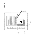
- FIG. 2 illustrates an example of a hand-held device or tablet-and-stylus computer 201 that can be used in accordance with various aspects of the invention. Any or all of the features, subsystems, and functions in the system of FIG. 1 can be included in the computer of FIG. 2 .
- Hand-held device or tablet-and-stylus computer 201 includes a large display surface 202 , e.g., a digitizing flat panel display, preferably, a liquid crystal display (LCD) screen, on which a plurality of windows 203 is displayed.
- a digitizing flat panel display e.g., a digitizing flat panel display, preferably, a liquid crystal display (LCD) screen
- a user can select, highlight, and/or write on the digitizing display surface 202 .
- LCD liquid crystal display
- Hand-held device or tablet-and-stylus computer 201 interprets gestures made using stylus 204 in order to manipulate data, enter text, create drawings, and/or execute conventional computer application tasks such as spreadsheets, word processing programs, and the like.
- a window 203 a allows a user to create electronic ink 206 using stylus 204 .
- the stylus 204 may be equipped with one or more buttons or other features to augment its selection capabilities.
- the stylus 204 could be implemented as a “pencil” or “pen,” in which one end constitutes a writing portion and the other end constitutes an “eraser” end, and which, when moved across the display, indicates to interested software that portions of the display are to be erased.
- Other types of input devices such as a mouse, trackball, or the like could be used.
- a user's finger could be the stylus 204 and used for selecting or indicating portions of the displayed image on a touch-sensitive or proximity-sensitive display.
- Region 205 shows a feedback region or contact region permitting the user to determine where the stylus 204 has contacted the display surface 202 .
- FIG. 3 is an illustrative method of calibrating a point device, such as a stylus 204 , respective to a writing surface, such as display surface 202 .
- the process may initiate for example, upon start up of the computing device, upon the passing of a predetermined period of time, or upon the occurrence of a specific event.
- data may be displayed to one or more users through a writing surface.
- the data may comprise text, graphics, or a combination thereof.
- the data is a graphical user interface (GUI), employing one or more applications, such as Microsoft® Windows® operating system.
- GUIs may comprise a plurality of graphical representations a user may interact with.
- Microsoft® Windows® operating system for example, comprises a GUI that includes buttons, tabs, toggle switches, windows that may be adjusted, such as resized, opened or closed, and a plurality of other mechanism for users to interact with the computing device. It is to be understood that operating systems are not the only application that may be utilized according to the many aspects of the invention. Indeed, the application may be software or hardware-based. In one embodiment, a plurality of applications may be concurrently displayed on a single display surface, such as display surface 202 , wherein a user may provide a user input, such as the input of step 310 (described below) to one or more applications.
- an operational user input is received at the computing device displaying the data of step 305 .
- the term operational user input relates to any user input from one or more input devices that is received to perform an intended function other than exclusively for calibration of the writing surface.
- Exemplary operational user inputs may include, but are not limited to, attempts from the user to click a button, resize, move or close a window, select a hyperlink or predetermined area of the display surface, toggle a switch, or otherwise interact with the writing surface. While the user input may be utilized for calibrating the writing surface, it is not received from the user for calibrating the writing surface.
- FIG. 4 shows an exemplary screen shot of data being displayed on a display device having a writing surface disposed thereon.
- the data comprises, inter alia, a button 405 , a hyperlink 410 , and an adjustable window 415 .
- FIG. 4 there are also exemplary groups of operational user inputs such as inputs 421 , 422 , and 423 (shown in close proximity to button 405 ) and inputs 426 , 427 , and 428 (shown in close proximity to hyperlink 410 ).
- the user inputs are shown merely for illustrative purpose to demonstrate the location on the writing surface that the operational user input was received.
- One skilled in the art will realize there may not be an actual graphical representation displayed on a display device to show the location of the operational user inputs, rather the inputs are shown for illustrative purposes to convey aspects of the invention.
- a miscalibration vector between the location on the writing surface of one or more operational user inputs and at least one expected location on the writing surface for the one or more operational user inputs is determined.
- proximity to a user selectable element may determine the intended or expected location of the operational user input(s).
- operational user input 421 is located in close proximity to button 405 .
- a “cut-off” value for determining a proximate user selectable input may be utilized. For example, a distance of 2 mm may be considered too distant to be considered the expected location.
- the type of user selectable element may determine the “cut-off” value. For example, a large button, such as button 405 may have a cut-off distance of 20 pixels, while a textual hyperlink may have a lesser cut-off value, for example, 0.5 mm.
- button 405 may be determined to be the expected or intended location of user input 421 if the user input is within the cut-off value.
- the cut-off distance may vary between the x-axis and the y-axis, for example, the user-selectable element is not square in shape, or proximity to other user-selectable elements.
- the cut-off distance is derived from what is “comfortably easy” to the target using a stylus or finger.
- the distance may readily be translated into pixels for one or more display devices by querying display characteristics from the display device(s).
- display characteristics from the display device(s).
- other units may be used to determine an expected location of a user input.
- the manner in which a particular user-selectable element may be selected by one or more users is considered when determining the intended or expected location of a received operational user input. This is especially useful when the user input(s) received in step 305 is in close proximity to a plurality of user-selectable elements.
- button 405 may only be selected or otherwise activated by receiving a signal indicated the user had “double tapped”, yet other elements, such as window 415 , are resized by users providing a “dragging” user input.
- FIG. 5 shows an exemplary screen shot of graphical data being displayed on a display device having a writing surface.
- Window 515 which may be similar to window 415 , is capable of being manipulated, such as being resized. Note, however, that window 515 is in close proximity to a plurality of buttons, text fields, and other user-selectable elements displayed on the display device.
- operational user inputs 520 and 550 have been received from a user and generally indicate a “dragging” motion, as the inputs begin with a starting point and proceed to the left to terminate in a ending point. Utilizing proximity alone, it would be difficult to determine intended location of the inputs.
- the type of user input received may aid in the determination of the expected or intended location 410 .
- a “dragging input” is received in close proximity to a button and a resizable window, it may be determined to be more likely to be intended to resize the window than to push the button. In this case, it may be readily determined that operational user inputs 520 , 525 were intended to resize window 515 .
- the intended location(s) of the operational input(s) is readily determinable.
- computer-executable instructions may “inspect” the type of object being dragged in a “dragging input” to determine whether the target location is the likely location. For example, text is often dragged to a text area while icons representing files are often dragged to file areas, for example, into a window of Windows® Explorer®.
- a plurality or user inputs may be required to be considered operational user inputs. This would be especially advantageous where a single stray user input may erroneously be utilized as an operational user input.
- optional step 320 may be utilized to determine if a plurality of user inputs have been received within a certain frame, such as for example, 5 seconds. In one such embodiment, only those inputs received within a predetermined period of time will be utilized.
- optional step 325 may be utilized in conjunction with or independent of step 320 to determine if a series of user inputs exhibit a level of precision to be considered operational user inputs where the user is attempting to interact with a particular user-selectable element.
- step 330 may be implemented to use that portion of the user inputs for calibration.
- the precision required for each type, class, or independent user-selectable element may vary in different embodiments of the invention.
- activation or button 405 , hyperlink 410 , and/or resizing of the window 415 performs a function other than calibration of the writing surface.
- miscalibration vector may be performed through any number of mechanisms known to those skilled in the art.
- a simple vector from the actual location of the user input to the expected or intended location is constructed on one or more axis (such as the x-axis representing the horizontal miscalibration and the y-axis representing the vertical miscalibration).
- non-calibration user input 421 may be estimated to be approximately +3 units miscalibrated in the x axis and approximately +4y units miscalibrated in the y axis. In one embodiment, these measurements will be used to construct a miscalibration vector for that particular location of the writing surface.
- the averages of a plurality of operational user inputs may be used, such as user inputs 421 , 422 , and 423 to determine the bias vector for that particular location (see, e.g., steps 320 / 325 ).
- buttons such as button 405 may provide a bias vector having x and y coordinates
- other user selectable elements provide more precise bias vectors on a single axis than may be obtainable with other elements.
- hyperlinks such as hyperlink 410
- operational user inputs 426 , 427 , and 428 may have a horizontal and a vertical coordinates, in at least one embodiment, only the vertical coordinate(s) may be used when constructing a miscalibration vector.
- hyperlink is shown as a mechanism for calibrating only the vertical axis, one skilled in the art will readily understand that any user-selectable element, including hyperlinks may also be utilized when determining vectors.
- EM fields whether from the computing device or an external source may cause miscalibration of the writing surface.
- the miscalibration may be permanent or temporary while the disturbing EM field is proximate to the computing device. Indeed, modifications in the configuration of the computer itself may warrant calibration.
- one or more modifications in a configuration parameter of the computing device are detected. Possible configuration modifications may include, but are not limited to changes in power sources, utilization of a hard drive, processors, and the location of the computing device. For example, it is known in the art that upon changing a computing device from direct current (DC) power to alternating current (AC) power, different electromagnetic fields may be produced on portions of the writing surface. Likewise, the location of a battery or power source may change the calibration.
- DC direct current
- AC alternating current
- the computing environment itself may cause different EM fields.
- a user who utilizes the computer at home may have different miscalibration vectors when the computer is used in his/her office. Therefore, upon detecting the computing device has switched to a new location, such as by detection of a new network, a modification of a configuration parameter is determined to have occurred.
- different users may hold the pointing device or stylus in a different manner, so switching users may be determined to be a modification in the configuration parameters.
- any alteration in the computing environment or computing device may alter the EM field on any portion of the writing surface may be considered a modification in a configuration parameter.
- step 310 may be reinitiated or otherwise increased to capture more operational user inputs.
- one or more schemes may be set up that automatically “adjust” the calibration of the writing surface upon specific modifications occurring, wherein the adjustment is determined by a plurality of operational user inputs previously collected.
- step 340 may be initiated to calculate a bias field for the writing surface.
- step 340 interpolates bias values for a given point on the writing surface based on the vectors of step 315 . As one skilled in the art will understand, there are many possibilities for interpolation methods.
- a weighted sum of all the vectors collected is computed.
- the weight of each vector is 1/R 2 , where R is the distance to the beginning point of that particular vector.
- the weighted sum may then be divided by a normalizing coefficient, such as for example, the sum of all the different weights.
- the inventors have found the above and similar approaches to work exceptionally well for their purposes as the result is a weighted average vector where the importance of all adjacent vectors drops off with R 2 .
- the 1/R 2 function is aggressively decaying, thus causing vectors close by to strongly dominate the weighted average.
- weighted average scheme allows two vectors that approximately equally close to a point to have approximately equal effect on the resulting vector, as opposed to just using the closest vector as the bias which would cause a vector just a little bit further than the closest to carry no weight at all.
- a weighted average vector where the weight is an exponential decay or some other aggressively decaying function could also work quite well.
- the bias field may be routinely updated as new operational user inputs are received in step 305 .
- modifications of configuration parameters may require the need for recalculation or adjustment of the bias field.
- the processes described above may occur without the user's knowledge, therefore the calibration may seem seamless and effortless to the user.
Abstract
Description
Claims (18)
Priority Applications (1)
| Application Number | Priority Date | Filing Date | Title |
|---|---|---|---|
| US11/358,816 US8004503B2 (en) | 2006-02-21 | 2006-02-21 | Auto-calibration of a touch screen |
Applications Claiming Priority (1)
| Application Number | Priority Date | Filing Date | Title |
|---|---|---|---|
| US11/358,816 US8004503B2 (en) | 2006-02-21 | 2006-02-21 | Auto-calibration of a touch screen |
Publications (2)
| Publication Number | Publication Date |
|---|---|
| US20070195067A1 US20070195067A1 (en) | 2007-08-23 |
| US8004503B2 true US8004503B2 (en) | 2011-08-23 |
Family
ID=38427694
Family Applications (1)
| Application Number | Title | Priority Date | Filing Date |
|---|---|---|---|
| US11/358,816 Expired - Fee Related US8004503B2 (en) | 2006-02-21 | 2006-02-21 | Auto-calibration of a touch screen |
Country Status (1)
| Country | Link |
|---|---|
| US (1) | US8004503B2 (en) |
Cited By (10)
| Publication number | Priority date | Publication date | Assignee | Title |
|---|---|---|---|---|
| US20110241907A1 (en) * | 2010-03-31 | 2011-10-06 | 3M Innovative Properties Company | Baseline update procedure for touch sensitive device |
| US20110296352A1 (en) * | 2010-05-27 | 2011-12-01 | Microsoft Corporation | Active calibration of a natural user interface |
| WO2013142958A1 (en) * | 2012-03-30 | 2013-10-03 | Smart Technologies Ulc | Method for generally continuously calibrating an interactive input system |
| US20140195923A1 (en) * | 2008-11-11 | 2014-07-10 | Adobe Systems Incorporated | Biometric Adjustments for Touchscreens |
| US20140267177A1 (en) * | 2013-03-15 | 2014-09-18 | Elwha, Llc | Systems and methods for parallax compensation |
| US8884928B1 (en) * | 2012-01-26 | 2014-11-11 | Amazon Technologies, Inc. | Correcting for parallax in electronic displays |
| US9389728B2 (en) | 2013-03-15 | 2016-07-12 | Elwha Llc | Systems and methods for parallax compensation |
| US9395902B2 (en) | 2013-03-15 | 2016-07-19 | Elwha Llc | Systems and methods for parallax compensation |
| US9898675B2 (en) | 2009-05-01 | 2018-02-20 | Microsoft Technology Licensing, Llc | User movement tracking feedback to improve tracking |
| US10025427B2 (en) | 2014-06-27 | 2018-07-17 | Microsoft Technology Licensing, Llc | Probabilistic touch sensing |
Families Citing this family (24)
| Publication number | Priority date | Publication date | Assignee | Title |
|---|---|---|---|---|
| AU2007237180B2 (en) * | 2006-11-27 | 2009-10-29 | Aristocrat Technologies Australia Pty Ltd | Gaming machine with touch screen |
| US8665225B2 (en) * | 2007-01-07 | 2014-03-04 | Apple Inc. | Portable multifunction device, method, and graphical user interface for interpreting a finger gesture |
| US8237665B2 (en) * | 2008-03-11 | 2012-08-07 | Microsoft Corporation | Interpreting ambiguous inputs on a touch-screen |
| US20090231282A1 (en) * | 2008-03-14 | 2009-09-17 | Steven Fyke | Character selection on a device using offset contact-zone |
| US8928595B2 (en) * | 2008-06-24 | 2015-01-06 | Microsoft Corporation | Touch screen calibration sensor |
| US8355022B2 (en) * | 2008-11-25 | 2013-01-15 | Sony Computer Entertainment America Llc | Method and apparatus for aggregating light sources per-vertex in computer graphics |
| US20100128038A1 (en) * | 2008-11-25 | 2010-05-27 | Sony Computer Entertainment America Inc. | Method and apparatus for interpolating color and direction as one entity in computer graphics |
| US9262073B2 (en) | 2010-05-20 | 2016-02-16 | John W. Howard | Touch screen with virtual joystick and methods for use therewith |
| US9542091B2 (en) | 2010-06-04 | 2017-01-10 | Apple Inc. | Device, method, and graphical user interface for navigating through a user interface using a dynamic object selection indicator |
| CN105659310B (en) | 2013-08-13 | 2021-02-26 | 飞利斯有限公司 | Optimization of electronic display area |
| CN105793781B (en) | 2013-08-27 | 2019-11-05 | 飞利斯有限公司 | Attachable device with deflection electronic component |
| WO2015031426A1 (en) | 2013-08-27 | 2015-03-05 | Polyera Corporation | Flexible display and detection of flex state |
| WO2015038684A1 (en) | 2013-09-10 | 2015-03-19 | Polyera Corporation | Attachable article with signaling, split display and messaging features |
| JP2017508493A (en) | 2013-12-24 | 2017-03-30 | ポリエラ コーポレイション | Support structure for flexible electronic components |
| WO2015100396A1 (en) | 2013-12-24 | 2015-07-02 | Polyera Corporation | Support structures for a flexible electronic component |
| WO2015100224A1 (en) | 2013-12-24 | 2015-07-02 | Polyera Corporation | Flexible electronic display with user interface based on sensed movements |
| JP6639400B2 (en) | 2013-12-24 | 2020-02-05 | フレックステラ, インコーポレイテッドFlexterra, Inc. | Support structure for attachable two-dimensional flexible electronic device |
| US20150227245A1 (en) | 2014-02-10 | 2015-08-13 | Polyera Corporation | Attachable Device with Flexible Electronic Display Orientation Detection |
| TWI692272B (en) | 2014-05-28 | 2020-04-21 | 美商飛利斯有限公司 | Device with flexible electronic components on multiple surfaces |
| US9898162B2 (en) | 2014-05-30 | 2018-02-20 | Apple Inc. | Swiping functions for messaging applications |
| US9971500B2 (en) | 2014-06-01 | 2018-05-15 | Apple Inc. | Displaying options, assigning notification, ignoring messages, and simultaneous user interface displays in a messaging application |
| WO2016138356A1 (en) | 2015-02-26 | 2016-09-01 | Polyera Corporation | Attachable device having a flexible electronic component |
| US10078410B1 (en) * | 2015-03-30 | 2018-09-18 | Electronic Arts Inc. | System to locomote an entity in three dimensional space |
| US10620812B2 (en) | 2016-06-10 | 2020-04-14 | Apple Inc. | Device, method, and graphical user interface for managing electronic communications |
Citations (17)
| Publication number | Priority date | Publication date | Assignee | Title |
|---|---|---|---|---|
| US4638119A (en) | 1984-11-16 | 1987-01-20 | Pencept, Inc. | Position indicating apparatus for use in a digitizing tablet system |
| US4697050A (en) | 1985-07-09 | 1987-09-29 | Alain Farel | Device for digitalizing graphical data |
| US5283559A (en) | 1992-09-21 | 1994-02-01 | International Business Machines Corp. | Automatic calibration of a capacitive touch screen used with a fixed element flat screen display panel |
| US5414227A (en) | 1993-04-29 | 1995-05-09 | International Business Machines Corporation | Stylus tilt detection apparatus for communication with a remote digitizing display |
| US5491706A (en) | 1993-04-07 | 1996-02-13 | Sharp Kabushiki Kaisha | Display-integrated type tablet device capable of detecting correct coordinates at a tip end of a detection pen by detecting external noise |
| US5751276A (en) | 1996-05-23 | 1998-05-12 | Microsoft Corporation | Method for calibrating touch panel displays |
| US5854449A (en) | 1995-09-11 | 1998-12-29 | Calcomp Inc. | High accuracy digitizer system |
| US6259436B1 (en) * | 1998-12-22 | 2001-07-10 | Ericsson Inc. | Apparatus and method for determining selection of touchable items on a computer touchscreen by an imprecise touch |
| US6262718B1 (en) * | 1994-01-19 | 2001-07-17 | International Business Machines Corporation | Touch-sensitive display apparatus |
| US6456952B1 (en) * | 2000-03-29 | 2002-09-24 | Ncr Coporation | System and method for touch screen environmental calibration |
| US6583676B2 (en) | 2001-06-20 | 2003-06-24 | Apple Computer, Inc. | Proximity/touch detector and calibration circuit |
| US20030169239A1 (en) | 2002-03-06 | 2003-09-11 | International Business Machines Corporation | Touch panel, control method, program, and storage medium |
| US6727896B2 (en) | 2001-08-01 | 2004-04-27 | Microsoft Corporation | Correction of alignment and linearity errors in a stylus input system |
| US6809726B2 (en) | 2000-12-11 | 2004-10-26 | Xerox Corporation | Touchscreen display calibration using results history |
| US20050093831A1 (en) | 2003-10-29 | 2005-05-05 | Han-Che Wang | Computer system and related method for calibrating a digitizer without utilizing calibration software |
| US20060007182A1 (en) * | 2004-07-08 | 2006-01-12 | Sony Corporation | Information-processing apparatus and programs used therein |
| US7190351B1 (en) * | 2002-05-10 | 2007-03-13 | Michael Goren | System and method for data input |
-
2006
- 2006-02-21 US US11/358,816 patent/US8004503B2/en not_active Expired - Fee Related
Patent Citations (17)
| Publication number | Priority date | Publication date | Assignee | Title |
|---|---|---|---|---|
| US4638119A (en) | 1984-11-16 | 1987-01-20 | Pencept, Inc. | Position indicating apparatus for use in a digitizing tablet system |
| US4697050A (en) | 1985-07-09 | 1987-09-29 | Alain Farel | Device for digitalizing graphical data |
| US5283559A (en) | 1992-09-21 | 1994-02-01 | International Business Machines Corp. | Automatic calibration of a capacitive touch screen used with a fixed element flat screen display panel |
| US5491706A (en) | 1993-04-07 | 1996-02-13 | Sharp Kabushiki Kaisha | Display-integrated type tablet device capable of detecting correct coordinates at a tip end of a detection pen by detecting external noise |
| US5414227A (en) | 1993-04-29 | 1995-05-09 | International Business Machines Corporation | Stylus tilt detection apparatus for communication with a remote digitizing display |
| US6262718B1 (en) * | 1994-01-19 | 2001-07-17 | International Business Machines Corporation | Touch-sensitive display apparatus |
| US5854449A (en) | 1995-09-11 | 1998-12-29 | Calcomp Inc. | High accuracy digitizer system |
| US5751276A (en) | 1996-05-23 | 1998-05-12 | Microsoft Corporation | Method for calibrating touch panel displays |
| US6259436B1 (en) * | 1998-12-22 | 2001-07-10 | Ericsson Inc. | Apparatus and method for determining selection of touchable items on a computer touchscreen by an imprecise touch |
| US6456952B1 (en) * | 2000-03-29 | 2002-09-24 | Ncr Coporation | System and method for touch screen environmental calibration |
| US6809726B2 (en) | 2000-12-11 | 2004-10-26 | Xerox Corporation | Touchscreen display calibration using results history |
| US6583676B2 (en) | 2001-06-20 | 2003-06-24 | Apple Computer, Inc. | Proximity/touch detector and calibration circuit |
| US6727896B2 (en) | 2001-08-01 | 2004-04-27 | Microsoft Corporation | Correction of alignment and linearity errors in a stylus input system |
| US20030169239A1 (en) | 2002-03-06 | 2003-09-11 | International Business Machines Corporation | Touch panel, control method, program, and storage medium |
| US7190351B1 (en) * | 2002-05-10 | 2007-03-13 | Michael Goren | System and method for data input |
| US20050093831A1 (en) | 2003-10-29 | 2005-05-05 | Han-Che Wang | Computer system and related method for calibrating a digitizer without utilizing calibration software |
| US20060007182A1 (en) * | 2004-07-08 | 2006-01-12 | Sony Corporation | Information-processing apparatus and programs used therein |
Non-Patent Citations (8)
| Title |
|---|
| Microsoft Windows XP, "Windows XP Tablet PC Edition 2005 Features" [online] Aug. 25, 2004 [retrieved on Feb. 2, 2006] Retrieved from the Internet: . |
| Microsoft Windows XP, "Windows XP Tablet PC Edition 2005 Features" [online] Aug. 25, 2004 [retrieved on Feb. 2, 2006] Retrieved from the Internet: <URL: http://ww.microsoft.com/windowsxp/tabletpc/evaluation/features.mspx?pf=true>. |
| NEC Solutions (America), Inc., "NEC Versa LitePad Tablet PC Digital Pen Set" [online] Feb. 2003 [retrieved on Feb. 2, 2006] Retrieved from the Internet: . |
| NEC Solutions (America), Inc., "NEC Versa LitePad Tablet PC Digital Pen Set" [online] Feb. 2003 [retrieved on Feb. 2, 2006] Retrieved from the Internet: <URL: http://support.necsam.com/mobilesolutions/hardware/TabletPCs/litepad/819-201012-000med.pdf>. |
| Ted Anthony, GlobeAndMail.com, "ThinkPad Tablet Gets It Right" [online] Jul. 29, 2005 [retrieved on Feb. 2, 2006] Associated Press, Copyright 2006 Bell Globemedia Publishing Inc. Retrieved from the Internet: . |
| Ted Anthony, GlobeAndMail.com, "ThinkPad Tablet Gets It Right" [online] Jul. 29, 2005 [retrieved on Feb. 2, 2006] Associated Press, Copyright 2006 Bell Globemedia Publishing Inc. Retrieved from the Internet: <URL: http://www.globetechnology.com/servlet/story/RTGAM.20050729.gtpadd0729/BNStory/TechReviews/>. |
| Wacom Company Ltd., "Wacom Graphire 3 Studio XL" [online] 2006 Wacom Europe GmbH [retrieved on Feb. 2, 2006] Retrieved from the Internet: . |
| Wacom Company Ltd., "Wacom Graphire 3 Studio XL" [online] 2006 Wacom Europe GmbH [retrieved on Feb. 2, 2006] Retrieved from the Internet: <URL: http://www.wacom-europe.com/int/products/graphire/product.asp?lang=en&type=14>. |
Cited By (16)
| Publication number | Priority date | Publication date | Assignee | Title |
|---|---|---|---|---|
| US20140195923A1 (en) * | 2008-11-11 | 2014-07-10 | Adobe Systems Incorporated | Biometric Adjustments for Touchscreens |
| US9927960B2 (en) * | 2008-11-11 | 2018-03-27 | Adobe Systems Incorporated | Biometric adjustments for touchscreens |
| US9898675B2 (en) | 2009-05-01 | 2018-02-20 | Microsoft Technology Licensing, Llc | User movement tracking feedback to improve tracking |
| US20110241907A1 (en) * | 2010-03-31 | 2011-10-06 | 3M Innovative Properties Company | Baseline update procedure for touch sensitive device |
| US8339286B2 (en) * | 2010-03-31 | 2012-12-25 | 3M Innovative Properties Company | Baseline update procedure for touch sensitive device |
| US20110296352A1 (en) * | 2010-05-27 | 2011-12-01 | Microsoft Corporation | Active calibration of a natural user interface |
| US8884928B1 (en) * | 2012-01-26 | 2014-11-11 | Amazon Technologies, Inc. | Correcting for parallax in electronic displays |
| US10019107B2 (en) | 2012-01-26 | 2018-07-10 | Amazon Technologies, Inc. | Correcting for parallax in electronic displays |
| US9360966B2 (en) | 2012-03-30 | 2016-06-07 | Smart Technologies Ulc | Method for generally continuously calibrating an interactive input system |
| WO2013142958A1 (en) * | 2012-03-30 | 2013-10-03 | Smart Technologies Ulc | Method for generally continuously calibrating an interactive input system |
| US9047002B2 (en) * | 2013-03-15 | 2015-06-02 | Elwha Llc | Systems and methods for parallax compensation |
| US9389728B2 (en) | 2013-03-15 | 2016-07-12 | Elwha Llc | Systems and methods for parallax compensation |
| US9395902B2 (en) | 2013-03-15 | 2016-07-19 | Elwha Llc | Systems and methods for parallax compensation |
| US9405402B2 (en) | 2013-03-15 | 2016-08-02 | Elwha Llc | Systems and methods for parallax compensation |
| US20140267177A1 (en) * | 2013-03-15 | 2014-09-18 | Elwha, Llc | Systems and methods for parallax compensation |
| US10025427B2 (en) | 2014-06-27 | 2018-07-17 | Microsoft Technology Licensing, Llc | Probabilistic touch sensing |
Also Published As
| Publication number | Publication date |
|---|---|
| US20070195067A1 (en) | 2007-08-23 |
Similar Documents
| Publication | Publication Date | Title |
|---|---|---|
| US8004503B2 (en) | Auto-calibration of a touch screen | |
| US9996176B2 (en) | Multi-touch uses, gestures, and implementation | |
| US10228833B2 (en) | Input device user interface enhancements | |
| EP1674976B1 (en) | Improving touch screen accuracy | |
| US7441202B2 (en) | Spatial multiplexing to mediate direct-touch input on large displays | |
| US8847904B2 (en) | Gesture recognition method and touch system incorporating the same | |
| JP6115867B2 (en) | Method and computing device for enabling interaction with an electronic device via one or more multi-directional buttons | |
| EP2507698B1 (en) | Three-state touch input system | |
| US20120154313A1 (en) | Multi-touch finger registration and its applications | |
| US20150185865A1 (en) | Keyboard with ntegrated touch surface | |
| US20100328236A1 (en) | Method for Controlling a Computer System and Related Computer System | |
| EP3100151B1 (en) | Virtual mouse for a touch screen device | |
| JP2013527539A5 (en) | ||
| US20140082559A1 (en) | Control area for facilitating user input | |
| WO2011045805A1 (en) | Gesture processing | |
| US20080062138A1 (en) | Computer system and control method therefor | |
| TW201319884A (en) | Touch control device and method | |
| US20140340335A1 (en) | System and method for data selection by means of a touch-sensitive surface | |
| Madhvanath et al. | GeCCo: Finger gesture-based command and control for touch interfaces | |
| JP5165624B2 (en) | Information input device, object display method, and computer-executable program | |
| Chen et al. | ScrollTest: Evaluating Scrolling Speed and Accuracy | |
| Go et al. | Touchscreen software keyboard for finger typing |
Legal Events
| Date | Code | Title | Description |
|---|---|---|---|
| AS | Assignment |
Owner name: MICROSOFT CORPORATION, WASHINGTON Free format text: ASSIGNMENT OF ASSIGNORS INTEREST;ASSIGNORS:TOWNSEND, REED;SHARIFF, SAMEER;DODGE, STEVE;AND OTHERS;REEL/FRAME:017447/0842;SIGNING DATES FROM 20050213 TO 20060214 Owner name: MICROSOFT CORPORATION, WASHINGTON Free format text: ASSIGNMENT OF ASSIGNORS INTEREST;ASSIGNORS:TOWNSEND, REED;SHARIFF, SAMEER;DODGE, STEVE;AND OTHERS;SIGNING DATES FROM 20050213 TO 20060214;REEL/FRAME:017447/0842 |
|
| FEPP | Fee payment procedure |
Free format text: PAYOR NUMBER ASSIGNED (ORIGINAL EVENT CODE: ASPN); ENTITY STATUS OF PATENT OWNER: LARGE ENTITY |
|
| STCF | Information on status: patent grant |
Free format text: PATENTED CASE |
|
| AS | Assignment |
Owner name: MICROSOFT TECHNOLOGY LICENSING, LLC, WASHINGTON Free format text: ASSIGNMENT OF ASSIGNORS INTEREST;ASSIGNOR:MICROSOFT CORPORATION;REEL/FRAME:034543/0001 Effective date: 20141014 |
|
| FPAY | Fee payment |
Year of fee payment: 4 |
|
| FEPP | Fee payment procedure |
Free format text: MAINTENANCE FEE REMINDER MAILED (ORIGINAL EVENT CODE: REM.); ENTITY STATUS OF PATENT OWNER: LARGE ENTITY |
|
| LAPS | Lapse for failure to pay maintenance fees |
Free format text: PATENT EXPIRED FOR FAILURE TO PAY MAINTENANCE FEES (ORIGINAL EVENT CODE: EXP.); ENTITY STATUS OF PATENT OWNER: LARGE ENTITY |
|
| STCH | Information on status: patent discontinuation |
Free format text: PATENT EXPIRED DUE TO NONPAYMENT OF MAINTENANCE FEES UNDER 37 CFR 1.362 |
|
| FP | Lapsed due to failure to pay maintenance fee |
Effective date: 20190823 |