US8089778B2 - Hand-held electronic device - Google Patents

Hand-held electronic device Download PDF

Info

Publication number
US8089778B2
US8089778B2 US12/139,572 US13957208A US8089778B2 US 8089778 B2 US8089778 B2 US 8089778B2 US 13957208 A US13957208 A US 13957208A US 8089778 B2 US8089778 B2 US 8089778B2
Authority
US
United States
Prior art keywords
touch
sensing
hand
electronic device
display area
Prior art date
Legal status (The legal status is an assumption and is not a legal conclusion. Google has not performed a legal analysis and makes no representation as to the accuracy of the status listed.)
Active, expires
Application number
US12/139,572
Other versions
US20090091545A1 (en
Inventor
Yi-Shen WANG
Yi-Chi Lin
Current Assignee (The listed assignees may be inaccurate. Google has not performed a legal analysis and makes no representation or warranty as to the accuracy of the list.)
HTC Corp
Original Assignee
HTC Corp
Priority date (The priority date is an assumption and is not a legal conclusion. Google has not performed a legal analysis and makes no representation as to the accuracy of the date listed.)
Filing date
Publication date
Application filed by HTC Corp filed Critical HTC Corp
Assigned to HIGH TECH COMPUTER CORP. reassignment HIGH TECH COMPUTER CORP. ASSIGNMENT OF ASSIGNORS INTEREST (SEE DOCUMENT FOR DETAILS). Assignors: LIN, YI-CHI, WANG, YI-SHEN
Publication of US20090091545A1 publication Critical patent/US20090091545A1/en
Assigned to HTC CORPORATION reassignment HTC CORPORATION ASSIGNMENT OF ASSIGNORS INTEREST (SEE DOCUMENT FOR DETAILS). Assignors: HIGH TECH COMPUTER CORP.
Application granted granted Critical
Publication of US8089778B2 publication Critical patent/US8089778B2/en
Active legal-status Critical Current
Adjusted expiration legal-status Critical

Links

Images

Classifications

    • GPHYSICS
    • G06COMPUTING; CALCULATING OR COUNTING
    • G06FELECTRIC DIGITAL DATA PROCESSING
    • G06F1/00Details not covered by groups G06F3/00 - G06F13/00 and G06F21/00
    • G06F1/16Constructional details or arrangements
    • G06F1/1613Constructional details or arrangements for portable computers
    • G06F1/1626Constructional details or arrangements for portable computers with a single-body enclosure integrating a flat display, e.g. Personal Digital Assistants [PDAs]
    • GPHYSICS
    • G06COMPUTING; CALCULATING OR COUNTING
    • G06FELECTRIC DIGITAL DATA PROCESSING
    • G06F1/00Details not covered by groups G06F3/00 - G06F13/00 and G06F21/00
    • G06F1/16Constructional details or arrangements
    • G06F1/1613Constructional details or arrangements for portable computers
    • G06F1/1633Constructional details or arrangements of portable computers not specific to the type of enclosures covered by groups G06F1/1615 - G06F1/1626
    • G06F1/1637Details related to the display arrangement, including those related to the mounting of the display in the housing
    • G06F1/1643Details related to the display arrangement, including those related to the mounting of the display in the housing the display being associated to a digitizer, e.g. laptops that can be used as penpads
    • GPHYSICS
    • G06COMPUTING; CALCULATING OR COUNTING
    • G06FELECTRIC DIGITAL DATA PROCESSING
    • G06F1/00Details not covered by groups G06F3/00 - G06F13/00 and G06F21/00
    • G06F1/16Constructional details or arrangements
    • G06F1/1613Constructional details or arrangements for portable computers
    • G06F1/1633Constructional details or arrangements of portable computers not specific to the type of enclosures covered by groups G06F1/1615 - G06F1/1626
    • G06F1/1656Details related to functional adaptations of the enclosure, e.g. to provide protection against EMI, shock, water, or to host detachable peripherals like a mouse or removable expansions units like PCMCIA cards, or to provide access to internal components for maintenance or to removable storage supports like CDs or DVDs, or to mechanically mount accessories
    • GPHYSICS
    • G06COMPUTING; CALCULATING OR COUNTING
    • G06FELECTRIC DIGITAL DATA PROCESSING
    • G06F3/00Input arrangements for transferring data to be processed into a form capable of being handled by the computer; Output arrangements for transferring data from processing unit to output unit, e.g. interface arrangements
    • G06F3/01Input arrangements or combined input and output arrangements for interaction between user and computer
    • G06F3/048Interaction techniques based on graphical user interfaces [GUI]
    • G06F3/0487Interaction techniques based on graphical user interfaces [GUI] using specific features provided by the input device, e.g. functions controlled by the rotation of a mouse with dual sensing arrangements, or of the nature of the input device, e.g. tap gestures based on pressure sensed by a digitiser
    • G06F3/0488Interaction techniques based on graphical user interfaces [GUI] using specific features provided by the input device, e.g. functions controlled by the rotation of a mouse with dual sensing arrangements, or of the nature of the input device, e.g. tap gestures based on pressure sensed by a digitiser using a touch-screen or digitiser, e.g. input of commands through traced gestures

Definitions

  • the invention relates in general to a hand-held electronic device, and more particularly to a hand-held electronic device having a touch-sensing display area and a holding area for avoiding an unexpected operation of the hand-held electronic device when the touch-sensing display area is touched unintentionally.
  • FIG. 1 shows a front view of a conventional hand-held electronic device 100 .
  • input keys 111 ⁇ 113 of the electronic device 100 are all located at two sides of a front surface.
  • a user's hand may still touch the input keys 111 ⁇ 113 to unintentionally operate the electronic device 100 via the input keys 111 ⁇ 113 while the user simply holds the device to read the displayed contents or only take a rest.
  • the user's hand unexpectedly presses at least one of the input keys 111 ⁇ 113 , an unexpected operation of the electronic device 100 would occur.
  • the invention is directed to a hand-held electronic device including a touch-sensing area and a holding area which are disposed separately.
  • the touch-sensing area is used for controlling the electronic device.
  • the holding area is used for allowing a user's hand to be rested thereon when the user does not operate the electronic device.
  • a hand-held electronic device including a body, a touch-sensing display area and a holding area.
  • the touch-sensing display area located at a surface of the body is divided into several sub-touch-sensing areas disposed at a part of a surrounding region of the touch-sensing display area.
  • the sub-touch-sensing areas have at least one access-sensing region.
  • the access-sensing region is used for sensing a touch-control action so as to render the hand-held electronic device to perform a function corresponding to the touch-control action.
  • the holding area is disposed outside the touch-sensing display area.
  • FIG. 1 (Prior Art) shows a front view of a conventional hand-held electronic device
  • FIG. 2A shows a front view of a hand-held electronic device according to an embodiment of the invention
  • FIG. 2B shows the hand-held electronic device in FIG. 2A held by the user
  • FIG. 2C shows the hand-held electronic device in FIG. 2A controlled by the user
  • FIGS. 3A , 3 B, 3 C, 3 D, 3 E and 3 F respectively show an example of a side view of the hand-held electronic device in FIG. 2A ;
  • FIG. 3G shows another example of a front view of the hand-held electronic device in FIG. 2A .
  • a hand-held electronic device includes a body, a touch-sensing display area and a holding area.
  • the touch-sensing display area located at a surface of the body is divided into several sub-touch-sensing areas disposed at a part of a surrounding region of the touch-sensing display area.
  • the sub-touch-sensing areas have at least one access-sensing region.
  • the access-sensing region is used for sensing a touch-control action so as to render the electronic device to perform a function corresponding to the touch-control action.
  • the holding area is disposed outside the touch-sensing display area.
  • the hand-held electronic device 200 includes a body (not illustrated), a touch-sensing display area 210 and a holding area 230 .
  • the touch-sensing display area 210 includes several sub-touch-sensing areas 220 disposed at a right side and a left side of the touch-sensing display area 210 .
  • the sub-touch-sensing areas 220 include several access-sensing regions 221 , 222 , 223 and 224 . When a user performs a touch-control action to one of the access-sensing regions, the hand-held electronic device 200 performs a corresponding function.
  • the holding area 230 is disposed outside the sub-touch-sensing areas 220 .
  • the hand-held electronic device 200 does not perform any corresponding function.
  • FIG. 2B shows the hand-held electronic device 200 in FIG. 2A held by the user.
  • the user can place his hand on the holding area 230 comfortably without an unexpected operation of the hand-held electronic device 200 resulting from the unintentional touch of the sub-touch-sensing areas 220 .
  • the holding area 230 further has the advantage of relaxing the user's hands.
  • FIG. 2C shows the hand-held electronic device 200 in FIG. 2A controlled by the user.
  • a touch-control action such as clicks the access-sensing region or drags on the access-sensing region, to at least one of the access-sensing regions 221 ⁇ 224 of the hand-held electronic device 200 in FIG. 2A , the hand-held electronic device 200 would perform a corresponding function.
  • FIG. 3A is an example of a side view of the hand-held electronic device 200 in FIG. 2A .
  • the holding area 230 of the hand-held electronic device 200 has a rougher surface structure.
  • the user can distinguish the sub-touch-sensing areas 220 from the holding area 230 only by the way of touch feeling without viewing it, so that the operation is more smoothly.
  • FIG. 3B and FIG. 3C are other two examples of side views of the hand-held electronic device 200 in FIG. 2A .
  • the surface of the holding area 230 of the hand-held electronic device 200 in FIG. 3B further has several protrusions.
  • the surface of the holding area 230 of the hand-held electronic device 200 in FIG. 3C further has several indentations.
  • the hand-held electronic device 200 in FIGS. 3A , 3 B and 3 C not only provides the convenient way to distinguish the sub-touch-sensing areas 220 from the holding area 230 by the way of touch feeling but also have the skidproof effect.
  • the different touch feelings are provided by the surface of the holding area 230 and that of the sub-touch-sensing areas 220 .
  • any designs enabling the surface of the holding area 230 and that of the sub-touch-sensing areas 220 to provide different touch feelings for being distinguished are within the scope of the invention.
  • FIG. 3D shows an example of a side view of the hand-held electronic device 200 in FIG. 2A .
  • the surface of the sub-touch-sensing areas 220 is located at a first plane, and the surface of the holding area 230 is located at a second plane. Thus, the sub-touch-sensing areas 220 and the holding area 230 are not co-planar.
  • FIG. 3E shows another example of a side view of the hand-held electronic device 200 in FIG. 2A .
  • the surface of the sub-touch-sensing areas 220 and the surface of the holding area 230 of the hand-held electronic device 200 form an inclined angle. The above two examples both allow the user to distinguish the sub-touch-sensing areas 220 from the holding area 230 by the way of viewing or touching.
  • FIG. 3F shows another example of a side view of the hand-held electronic device 200 in FIG. 2A .
  • At least one separation structure 240 is disposed between the sub-touch-sensing areas 220 and the holding area 230 , so that the user can distinguish the position of the sub-touch-sensing areas 220 from that of the holding area 230 by the way of viewing or touching.
  • the separation structure 240 of the hand-held electronic device 200 is exemplified by a protruded structure.
  • any separation structures such as an indented structure or a light-emitting warning structure (LED or backlight), enabling the user to distinguish the position of the sub-touch-sensing areas 220 from that of the holding area 230 can be used in the hand-held electronic device 200 .
  • FIG. 3G shows another example of a front view of the hand-held electronic device 200 in FIG. 2A .
  • a width between a first side 233 and a second side 234 of the holding area 230 of the hand-held electronic device 200 is not less than 10 mm.
  • the interval between the first side 233 and the second side 234 of the holding area 230 is designed to be an appropriate width W, so that the user would not unexpectedly touch the sub-touch-sensing areas 220 while merely holding the hand-held electronic device 200 and placing his hand on the holding area 230 . Meanwhile, the user's hand can avoid being tired.
  • the first side 233 is adjacent to the sub-touch-sensing areas 220 , and the second side 234 is disposed at a side edge of the body of the hand-held electronic device 200 .
  • the appropriate width W is not less than 10 mm.
  • the hand-held electronic device 200 disposed with the sub-touch-sensing areas 220 at the right side and the left side of the touch-sensing display area 210 is illustrated, but the practical applications are not limited thereto. Any hand-held electronic device having touch-sensing areas at any regions of the surrounding of the display area is within the scope of the invention.
  • the hand-held electronic device 200 having four access-sensing regions 221 ⁇ 224 is illustrated, but practical applications are not limited to the four access-sensing regions. Any hand-held electronic devices having any number of access-sensing regions or having access-sensing regions disposed at any part of the sub-touch-sensing areas 220 are within the scope of the invention.
  • the input keys of the conventional hand-held electronic device are replaced by the several sub-touch-sensing areas of the hand-held electronic device according to the embodiment of the invention.
  • the sub-touch-sensing areas further cooperate with the holding area, so that the sub-touch-sensing areas are not touched unexpectedly when the user does not operate the hand-held electronic device. Therefore, the risk of the unexpected operation of the hand-held electronic device is reduced.
  • the sub-touch-sensing areas divided into several access-sensing regions can save space and increase the space utilization.
  • the space outside the touch-sensing display area of the hand-held electronic device can be saved.
  • the user is provided with smooth control experience by using the access-sensing region of the hand-held electronic device without increasing the size and sacrificing functions of the hand-held electronic device.
  • another advantage of replacing the input keys of the conventional technology with the sub-touch-sensing areas is that the size of the mechanical structure can be reduced and the hand-held electronic device becomes further thinned.

Abstract

A hand-held electronic device including a body, a touch-sensing display area, and a holding area is provided. The touch-sensing display area located at a surface of the body is divided into several sub-touch-sensing areas disposed at a part of a surrounding region of the touch-sensing display area. The sub-touch-sensing areas have at least one access-sensing region. The access-sensing region is used for sensing a touch-control action so as to render the hand-held electronic device to perform a function corresponding to the touch-control action. The holding area is disposed outside the sub-touch-sensing areas. When a user only intends to hold the hand-held electronic device, the user's hands can put on the holding area and the hand-held electronic device would not perform any corresponding function.

Description

This application claims the benefit of Taiwan application Serial No. 096137155, filed Oct. 03, 2007, the subject matter of which is incorporated herein by reference.
BACKGROUND OF THE INVENTION
1. Field of the Invention
The invention relates in general to a hand-held electronic device, and more particularly to a hand-held electronic device having a touch-sensing display area and a holding area for avoiding an unexpected operation of the hand-held electronic device when the touch-sensing display area is touched unintentionally.
2. Description of the Related Art
The development trend of hand-held electronic device directs toward smaller, thinner and lighter for being conveniently bringing. However, many conventional hand-held electronic devices are disposed with input control keys on front surfaces thereof, so that a large portion of the devices' tiny front surfaces are occupied. As the space of the front surface is limited, users frequently touch the input control keys unintentionally to cause an unexpected operation of the device while simply holding the device.
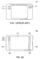
FIG. 1 shows a front view of a conventional hand-held electronic device 100. Referring to FIG. 1, input keys 111˜113 of the electronic device 100 are all located at two sides of a front surface. As the space of the front surface of the electronic device 100 is limited, a user's hand may still touch the input keys 111˜113 to unintentionally operate the electronic device 100 via the input keys 111˜113 while the user simply holds the device to read the displayed contents or only take a rest. At this time, if the user's hand unexpectedly presses at least one of the input keys 111˜113, an unexpected operation of the electronic device 100 would occur.
SUMMARY OF THE INVENTION
The invention is directed to a hand-held electronic device including a touch-sensing area and a holding area which are disposed separately. The touch-sensing area is used for controlling the electronic device. The holding area is used for allowing a user's hand to be rested thereon when the user does not operate the electronic device. With the separate disposition of the touch-sensing area and the holding area, the invention resolves an unexpected operation problem occurring to the conventional hand-held electronic device due to the input keys often being unintentionally touched when the user merely holds the electronic device.
According to the present invention, a hand-held electronic device including a body, a touch-sensing display area and a holding area is provided. The touch-sensing display area located at a surface of the body is divided into several sub-touch-sensing areas disposed at a part of a surrounding region of the touch-sensing display area. The sub-touch-sensing areas have at least one access-sensing region. The access-sensing region is used for sensing a touch-control action so as to render the hand-held electronic device to perform a function corresponding to the touch-control action. The holding area is disposed outside the touch-sensing display area.
The invention will become apparent from the following detailed description of the preferred but non-limiting embodiments. The following description is made with reference to the accompanying drawings.
BRIEF DESCRIPTION OF THE DRAWINGS
FIG. 1 (Prior Art) shows a front view of a conventional hand-held electronic device;
FIG. 2A shows a front view of a hand-held electronic device according to an embodiment of the invention;
FIG. 2B shows the hand-held electronic device in FIG. 2A held by the user;
FIG. 2C shows the hand-held electronic device in FIG. 2A controlled by the user;
FIGS. 3A, 3B, 3C, 3D, 3E and 3F respectively show an example of a side view of the hand-held electronic device in FIG. 2A; and
FIG. 3G shows another example of a front view of the hand-held electronic device in FIG. 2A.
DETAILED DESCRIPTION OF THE INVENTION
A hand-held electronic device according to the invention includes a body, a touch-sensing display area and a holding area. The touch-sensing display area located at a surface of the body is divided into several sub-touch-sensing areas disposed at a part of a surrounding region of the touch-sensing display area. The sub-touch-sensing areas have at least one access-sensing region. The access-sensing region is used for sensing a touch-control action so as to render the electronic device to perform a function corresponding to the touch-control action. The holding area is disposed outside the touch-sensing display area.
Referring to FIG. 2A, a front view of a hand-held electronic device according to an embodiment of the invention is shown. The hand-held electronic device 200 includes a body (not illustrated), a touch-sensing display area 210 and a holding area 230. The touch-sensing display area 210 includes several sub-touch-sensing areas 220 disposed at a right side and a left side of the touch-sensing display area 210. The sub-touch-sensing areas 220 include several access- sensing regions 221, 222, 223 and 224. When a user performs a touch-control action to one of the access-sensing regions, the hand-held electronic device 200 performs a corresponding function.
The holding area 230 is disposed outside the sub-touch-sensing areas 220. When the user's hand is merely placed on the holding area 230, the hand-held electronic device 200 does not perform any corresponding function. FIG. 2B shows the hand-held electronic device 200 in FIG. 2A held by the user. When the user only wants to hold the hand-held electronic device 200 by one hand or both hands, the user can place his hand on the holding area 230 comfortably without an unexpected operation of the hand-held electronic device 200 resulting from the unintentional touch of the sub-touch-sensing areas 220. It shows that no matter the user holds the hand-held electronic device 200 by one hand or both hands, the user's hand would not be taut because of worrying about the unexpection touch of the sub-touch-sensing areas 220. Therefore, the holding area 230 further has the advantage of relaxing the user's hands.
FIG. 2C shows the hand-held electronic device 200 in FIG. 2A controlled by the user. When the user performs a touch-control action, such as clicks the access-sensing region or drags on the access-sensing region, to at least one of the access-sensing regions 221˜224 of the hand-held electronic device 200 in FIG. 2A, the hand-held electronic device 200 would perform a corresponding function.
In order to operate smoothly, the distinguishability between the sub-touch-sensing areas 220 and the holding area 230 is needed. To further distinguish the sub-touch-sensing areas 220 from the holding area 230, the sub-touch-sensing areas 220 and the holding area 230 can be designed to have different surface structures, so that the user can distinguish the sub-touch-sensing areas 220 from the holding area 230 by the way of different touch feeling. Practically, the user can be reminded or warned that if his hand is placed at an appropriate position. FIG. 3A is an example of a side view of the hand-held electronic device 200 in FIG. 2A. Compared to the sub-touch-sensing areas 220, the holding area 230 of the hand-held electronic device 200 has a rougher surface structure. When the user operates the hand-held electronic device 200, the user can distinguish the sub-touch-sensing areas 220 from the holding area 230 only by the way of touch feeling without viewing it, so that the operation is more smoothly. FIG. 3B and FIG. 3C are other two examples of side views of the hand-held electronic device 200 in FIG. 2A. The surface of the holding area 230 of the hand-held electronic device 200 in FIG. 3B further has several protrusions. The surface of the holding area 230 of the hand-held electronic device 200 in FIG. 3C further has several indentations. The hand-held electronic device 200 in FIGS. 3A, 3B and 3C not only provides the convenient way to distinguish the sub-touch-sensing areas 220 from the holding area 230 by the way of touch feeling but also have the skidproof effect.
In the above three examples, the different touch feelings are provided by the surface of the holding area 230 and that of the sub-touch-sensing areas 220. However, in practical applications, any designs enabling the surface of the holding area 230 and that of the sub-touch-sensing areas 220 to provide different touch feelings for being distinguished are within the scope of the invention.
FIG. 3D shows an example of a side view of the hand-held electronic device 200 in FIG. 2A. The surface of the sub-touch-sensing areas 220 is located at a first plane, and the surface of the holding area 230 is located at a second plane. Thus, the sub-touch-sensing areas 220 and the holding area 230 are not co-planar. FIG. 3E shows another example of a side view of the hand-held electronic device 200 in FIG. 2A. The surface of the sub-touch-sensing areas 220 and the surface of the holding area 230 of the hand-held electronic device 200 form an inclined angle. The above two examples both allow the user to distinguish the sub-touch-sensing areas 220 from the holding area 230 by the way of viewing or touching.
FIG. 3F shows another example of a side view of the hand-held electronic device 200 in FIG. 2A. At least one separation structure 240 is disposed between the sub-touch-sensing areas 220 and the holding area 230, so that the user can distinguish the position of the sub-touch-sensing areas 220 from that of the holding area 230 by the way of viewing or touching. In FIG. 3F, the separation structure 240 of the hand-held electronic device 200 is exemplified by a protruded structure. In practical applications, any separation structures, such as an indented structure or a light-emitting warning structure (LED or backlight), enabling the user to distinguish the position of the sub-touch-sensing areas 220 from that of the holding area 230 can be used in the hand-held electronic device 200.
FIG. 3G shows another example of a front view of the hand-held electronic device 200 in FIG. 2A. A width between a first side 233 and a second side 234 of the holding area 230 of the hand-held electronic device 200 is not less than 10 mm. The interval between the first side 233 and the second side 234 of the holding area 230 is designed to be an appropriate width W, so that the user would not unexpectedly touch the sub-touch-sensing areas 220 while merely holding the hand-held electronic device 200 and placing his hand on the holding area 230. Meanwhile, the user's hand can avoid being tired. The first side 233 is adjacent to the sub-touch-sensing areas 220, and the second side 234 is disposed at a side edge of the body of the hand-held electronic device 200. In the present embodiment of the invention, the appropriate width W is not less than 10 mm.
In the present embodiment of the invention, the hand-held electronic device 200 disposed with the sub-touch-sensing areas 220 at the right side and the left side of the touch-sensing display area 210 is illustrated, but the practical applications are not limited thereto. Any hand-held electronic device having touch-sensing areas at any regions of the surrounding of the display area is within the scope of the invention.
In the present embodiment of the invention, the hand-held electronic device 200 having four access-sensing regions 221˜224 is illustrated, but practical applications are not limited to the four access-sensing regions. Any hand-held electronic devices having any number of access-sensing regions or having access-sensing regions disposed at any part of the sub-touch-sensing areas 220 are within the scope of the invention.
In the present embodiment of the invention, the input keys of the conventional hand-held electronic device are replaced by the several sub-touch-sensing areas of the hand-held electronic device according to the embodiment of the invention. The sub-touch-sensing areas further cooperate with the holding area, so that the sub-touch-sensing areas are not touched unexpectedly when the user does not operate the hand-held electronic device. Therefore, the risk of the unexpected operation of the hand-held electronic device is reduced. Compared with the conventional hand-held electronic device disposed with the separate input keys, the sub-touch-sensing areas divided into several access-sensing regions can save space and increase the space utilization. Under the condition of the same-size displaying area, the space outside the touch-sensing display area of the hand-held electronic device can be saved. In addition, the user is provided with smooth control experience by using the access-sensing region of the hand-held electronic device without increasing the size and sacrificing functions of the hand-held electronic device. Furthermore, another advantage of replacing the input keys of the conventional technology with the sub-touch-sensing areas is that the size of the mechanical structure can be reduced and the hand-held electronic device becomes further thinned.
While the invention has been described by way of example and in terms of a preferred embodiment, it is to be understood that the invention is not limited thereto. On the contrary, it is intended to cover various modifications and similar arrangements and procedures, and the scope of the appended claims therefore should be accorded the broadest interpretation so as to encompass all such modifications and similar arrangements and procedures.

Claims (17)

1. A hand-held electronic device, comprising: a body; a touch-sensing display area located at a surface of the body, wherein the touch-sensing display area further comprises a plurality of sub-touch-sensing areas disposed at a part of a surrounding region of the touch-sensing display area; a holding area disposed outside the touch-sensing display area; and a separation structure disposed between the holding area and the touch-sensing display area, wherein a first side of the holding area is adjacent to the touch-sensing display area, a second side of the holding area is disposed at a side edge of the body, and a width between the first side and the second side is not less than 10 mm.
2. The device according to claim 1, wherein the sub-touch-sensing areas have at least one access-sensing region for sensing a touch-control action so as to render the hand-held electronic device to perform a function corresponding to the touch-control action.
3. The device according to claim 1, wherein a surface of the holding area is located at a first plane and a surface of the touch-sensing display area is located at a second plane.
4. The device according to claim 1, wherein a surface of the holding area and a surface of the touch-sensing display area form an inclined angle.
5. The device according to claim 1, wherein the holding area has a first surface structure and the touch-sensing display area has a second surface structure.
6. The device according to claim 1, wherein a surface of the holding area further has a plurality of protrusions.
7. The device according to claim 1, wherein a surface of the holding area further has a plurality of indentations.
8. The device according to claim 1, the separation structure is a protruded structure, an indented structure or a light-emitting structure.
9. The device according to claim 1, one of the sub-touch-sensing areas is disposed at a left side and/or a right side of the touch-sensing display area.
10. A hand-held electronic device, comprising:
a body;
a touch-sensing display area located at a surface of the body, wherein the touch-sensing display area further comprises a plurality of sub-touch-sensing areas disposed at a part of a surrounding region of the touch-sensing display area; and
a holding area disposed outside the touch-sensing display area;
wherein the holding area has a first surface structure and the touch-sensing display area has a second surface structure, the first surface structure having a plurality of protrusions or a plurality of indentations.
11. The device according to claim 10, wherein the sub-touch-sensing areas have at least one access-sensing region for sensing a touch-control action so as to render the hand-held electronic device to perform a function corresponding to the touch-control action.
12. The device according to claim 10, wherein a surface of the holding area is located at a first plane and a surface of the touch-sensing display area is located at a second plane.
13. The device according to claim 10, wherein a surface of the holding area and a surface of the touch-sensing display area form an inclined angle.
14. The device according to claim 10, wherein the device further comprises a separation structure disposed between the holding area and the touch-sensing display area.
15. The device according to claim 14, the separation structure is a protruded structure, an indented structure or a light-emitting structure.
16. The device according to claim 10, one of the sub-touch-sensing areas is disposed at a left side and/or a right side of the touch-sensing display area.
17. The device according to claim 10, wherein a first side of the holding area is adjacent to the touch-sensing display area, a second side of the holding area is disposed at a side edge of the body, and a width between the first side and the second side is not less than 10 mm.
US12/139,572 2007-10-03 2008-06-16 Hand-held electronic device Active 2030-10-12 US8089778B2 (en)

Applications Claiming Priority (3)

Application Number Priority Date Filing Date Title
TW96137155A 2007-10-03
TW96137155 2007-10-03
TW096137155A TWI375161B (en) 2007-10-03 2007-10-03 Hand-held electronic device

Publications (2)

Publication Number Publication Date
US20090091545A1 US20090091545A1 (en) 2009-04-09
US8089778B2 true US8089778B2 (en) 2012-01-03

Family

ID=40522858

Family Applications (1)

Application Number Title Priority Date Filing Date
US12/139,572 Active 2030-10-12 US8089778B2 (en) 2007-10-03 2008-06-16 Hand-held electronic device

Country Status (2)

Country Link
US (1) US8089778B2 (en)
TW (1) TWI375161B (en)

Cited By (4)

* Cited by examiner, † Cited by third party
Publication number Priority date Publication date Assignee Title
US20120154408A1 (en) * 2010-12-20 2012-06-21 Yukawa Shuhei Information processing apparatus and information processing method
US20120326984A1 (en) * 2009-12-20 2012-12-27 Benjamin Firooz Ghassabian Features of a data entry system
US20130067397A1 (en) * 2011-09-12 2013-03-14 Microsoft Corporation Control area for a touch screen
US9389703B1 (en) * 2014-06-23 2016-07-12 Amazon Technologies, Inc. Virtual screen bezel

Families Citing this family (9)

* Cited by examiner, † Cited by third party
Publication number Priority date Publication date Assignee Title
JP4670970B2 (en) * 2009-01-28 2011-04-13 ソニー株式会社 Display input device
WO2011065249A1 (en) * 2009-11-25 2011-06-03 日本電気株式会社 Portable information terminal, input control method, and program
KR20110069476A (en) * 2009-12-17 2011-06-23 주식회사 아이리버 Hand hrld electronic device to reflecting grip of user and method thereof
JP5485245B2 (en) * 2011-10-26 2014-05-07 シャープ株式会社 Input device for image forming apparatus and image forming apparatus
JP5913005B2 (en) * 2012-08-29 2016-04-27 京セラ株式会社 Portable terminal, control method and control program
JP2014106937A (en) * 2012-11-30 2014-06-09 Toshiba Corp Electronic apparatus
CN103927144B (en) * 2014-04-17 2019-03-15 努比亚技术有限公司 The method and device of contact action
US10209821B2 (en) * 2016-04-05 2019-02-19 Google Llc Computing devices having swiping interfaces and methods of operating the same
KR20230071927A (en) * 2021-11-16 2023-05-24 삼성디스플레이 주식회사 Touch sensor and display device including the same

Citations (8)

* Cited by examiner, † Cited by third party
Publication number Priority date Publication date Assignee Title
US4969647A (en) * 1989-06-02 1990-11-13 Atari Corporation Invertible hand-held electronic game apparatus
US6088024A (en) 1997-06-13 2000-07-11 Nec Corporation Touch panel and method for detecting a pressed position on a touch panel
CN1638616A (en) 2004-01-07 2005-07-13 索尼公司 Electronic device with display screen
TW200526306A (en) 2003-09-26 2005-08-16 Sony Computer Entertainment Inc Portable electronic apparatus
US20060238517A1 (en) 2005-03-04 2006-10-26 Apple Computer, Inc. Electronic Device Having Display and Surrounding Touch Sensitive Bezel for User Interface and Control
US20070152980A1 (en) * 2006-01-05 2007-07-05 Kenneth Kocienda Touch Screen Keyboards for Portable Electronic Devices
US20080007539A1 (en) * 2006-07-06 2008-01-10 Steve Hotelling Mutual capacitance touch sensing device
US7499284B2 (en) * 2005-05-16 2009-03-03 Nintendo Co., Ltd. Hand-held game machine and cover

Patent Citations (9)

* Cited by examiner, † Cited by third party
Publication number Priority date Publication date Assignee Title
US4969647A (en) * 1989-06-02 1990-11-13 Atari Corporation Invertible hand-held electronic game apparatus
US6088024A (en) 1997-06-13 2000-07-11 Nec Corporation Touch panel and method for detecting a pressed position on a touch panel
TW200526306A (en) 2003-09-26 2005-08-16 Sony Computer Entertainment Inc Portable electronic apparatus
CN1638616A (en) 2004-01-07 2005-07-13 索尼公司 Electronic device with display screen
US7365808B2 (en) 2004-01-07 2008-04-29 Sony Corporation Electronic device having a display
US20060238517A1 (en) 2005-03-04 2006-10-26 Apple Computer, Inc. Electronic Device Having Display and Surrounding Touch Sensitive Bezel for User Interface and Control
US7499284B2 (en) * 2005-05-16 2009-03-03 Nintendo Co., Ltd. Hand-held game machine and cover
US20070152980A1 (en) * 2006-01-05 2007-07-05 Kenneth Kocienda Touch Screen Keyboards for Portable Electronic Devices
US20080007539A1 (en) * 2006-07-06 2008-01-10 Steve Hotelling Mutual capacitance touch sensing device

Non-Patent Citations (3)

* Cited by examiner, † Cited by third party
Title
English language translation of abstract of CN 1638616 (published Jul. 13, 2005).
English language translation of abstract of TW 200526306 (published Aug. 16, 2005).
Taiwanese language office action dated May 4, 2011.

Cited By (7)

* Cited by examiner, † Cited by third party
Publication number Priority date Publication date Assignee Title
US20120326984A1 (en) * 2009-12-20 2012-12-27 Benjamin Firooz Ghassabian Features of a data entry system
US9304602B2 (en) * 2009-12-20 2016-04-05 Keyless Systems Ltd. System for capturing event provided from edge of touch screen
US20120154408A1 (en) * 2010-12-20 2012-06-21 Yukawa Shuhei Information processing apparatus and information processing method
US10955958B2 (en) * 2010-12-20 2021-03-23 Sony Corporation Information processing apparatus and information processing method
US20130067397A1 (en) * 2011-09-12 2013-03-14 Microsoft Corporation Control area for a touch screen
US10318146B2 (en) * 2011-09-12 2019-06-11 Microsoft Technology Licensing, Llc Control area for a touch screen
US9389703B1 (en) * 2014-06-23 2016-07-12 Amazon Technologies, Inc. Virtual screen bezel

Also Published As

Publication number Publication date
TW200917096A (en) 2009-04-16
TWI375161B (en) 2012-10-21
US20090091545A1 (en) 2009-04-09

Similar Documents

Publication Publication Date Title
US8089778B2 (en) Hand-held electronic device
TWI527072B (en) Keyboard assembly for an electronic device, and method and system of keyboard configurations for an electronic device
CN104238808B (en) Hand-hold electronic equipments, handheld device and its operating method
US20150335116A1 (en) Protective case for mobile device
WO2012049942A1 (en) Mobile terminal device and display method for touch panel in mobile terminal device
TWI539327B (en) Dual configuration computer
JP5667002B2 (en) Computer input device and portable computer
JP2003140804A (en) Information processor
JPH0651865A (en) Portable computer system, keyboard of computer system and pointing device of computer system
US7705827B1 (en) Ergonomic computer mouse
US20060044281A1 (en) Portable electronic device
US7929282B2 (en) Keyboard
US20080024957A1 (en) Portable apparatus with thumb control interface
US8125775B2 (en) Thin type mouse
US20070036603A1 (en) Portable keyboard
JP2008176720A (en) Input auxiliary implement
US8482528B2 (en) Ultra mobile personal computer
US20130174319A1 (en) Handpad for touchscreen of an electric device
US8350813B2 (en) Digitizer and input device
JP2000105630A (en) Portable computer
KR101616668B1 (en) Mouse pad device for using in touchpad mouse
JP2014099109A (en) Keyboard panel and input device
JP2004220506A (en) Writing input device and pen
JP6865920B2 (en) Touch panel sheet and information terminal
JP3241590U (en) mobile phone cover

Legal Events

Date Code Title Description
AS Assignment

Owner name: HIGH TECH COMPUTER CORP., TAIWAN

Free format text: ASSIGNMENT OF ASSIGNORS INTEREST;ASSIGNORS:WANG, YI-SHEN;LIN, YI-CHI;REEL/FRAME:021099/0199

Effective date: 20080610

AS Assignment

Owner name: HTC CORPORATION, TAIWAN

Free format text: ASSIGNMENT OF ASSIGNORS INTEREST;ASSIGNOR:HIGH TECH COMPUTER CORP.;REEL/FRAME:027289/0821

Effective date: 20080613

STCF Information on status: patent grant

Free format text: PATENTED CASE

FPAY Fee payment

Year of fee payment: 4

MAFP Maintenance fee payment

Free format text: PAYMENT OF MAINTENANCE FEE, 8TH YEAR, LARGE ENTITY (ORIGINAL EVENT CODE: M1552); ENTITY STATUS OF PATENT OWNER: LARGE ENTITY

Year of fee payment: 8

MAFP Maintenance fee payment

Free format text: PAYMENT OF MAINTENANCE FEE, 12TH YEAR, LARGE ENTITY (ORIGINAL EVENT CODE: M1553); ENTITY STATUS OF PATENT OWNER: LARGE ENTITY

Year of fee payment: 12