US9069428B2 - Method for the operator control of a matrix touchscreen - Google Patents
Method for the operator control of a matrix touchscreen Download PDFInfo
- Publication number
- US9069428B2 US9069428B2 US13/982,325 US201113982325A US9069428B2 US 9069428 B2 US9069428 B2 US 9069428B2 US 201113982325 A US201113982325 A US 201113982325A US 9069428 B2 US9069428 B2 US 9069428B2
- Authority
- US
- United States
- Prior art keywords
- matrix
- touch screen
- signal level
- touch
- sampling time
- Prior art date
- Legal status (The legal status is an assumption and is not a legal conclusion. Google has not performed a legal analysis and makes no representation as to the accuracy of the status listed.)
- Active, expires
Links
- 239000011159 matrix material Substances 0.000 title claims abstract description 198
- 238000000034 method Methods 0.000 title claims abstract description 29
- 238000005070 sampling Methods 0.000 claims description 79
- 230000003247 decreasing effect Effects 0.000 claims description 3
- 230000006870 function Effects 0.000 description 36
- 238000006073 displacement reaction Methods 0.000 description 6
- 210000003813 thumb Anatomy 0.000 description 6
- 238000001514 detection method Methods 0.000 description 3
- 210000003811 finger Anatomy 0.000 description 3
- 230000000007 visual effect Effects 0.000 description 3
- 238000004378 air conditioning Methods 0.000 description 2
- 230000001419 dependent effect Effects 0.000 description 2
- 238000010586 diagram Methods 0.000 description 2
- 238000002372 labelling Methods 0.000 description 2
- 238000002485 combustion reaction Methods 0.000 description 1
- 238000004519 manufacturing process Methods 0.000 description 1
- 102220184965 rs117987946 Human genes 0.000 description 1
- 102220131033 rs145667920 Human genes 0.000 description 1
- 102220062245 rs1800369 Human genes 0.000 description 1
- 102220039198 rs7243081 Human genes 0.000 description 1
- 102220139156 rs774350715 Human genes 0.000 description 1
- 102220059961 rs786201335 Human genes 0.000 description 1
- 230000005236 sound signal Effects 0.000 description 1
Images


Classifications
-
- G—PHYSICS
- G06—COMPUTING; CALCULATING OR COUNTING
- G06F—ELECTRIC DIGITAL DATA PROCESSING
- G06F3/00—Input arrangements for transferring data to be processed into a form capable of being handled by the computer; Output arrangements for transferring data from processing unit to output unit, e.g. interface arrangements
- G06F3/01—Input arrangements or combined input and output arrangements for interaction between user and computer
- G06F3/03—Arrangements for converting the position or the displacement of a member into a coded form
- G06F3/041—Digitisers, e.g. for touch screens or touch pads, characterised by the transducing means
- G06F3/044—Digitisers, e.g. for touch screens or touch pads, characterised by the transducing means by capacitive means
-
- B—PERFORMING OPERATIONS; TRANSPORTING
- B60—VEHICLES IN GENERAL
- B60K—ARRANGEMENT OR MOUNTING OF PROPULSION UNITS OR OF TRANSMISSIONS IN VEHICLES; ARRANGEMENT OR MOUNTING OF PLURAL DIVERSE PRIME-MOVERS IN VEHICLES; AUXILIARY DRIVES FOR VEHICLES; INSTRUMENTATION OR DASHBOARDS FOR VEHICLES; ARRANGEMENTS IN CONNECTION WITH COOLING, AIR INTAKE, GAS EXHAUST OR FUEL SUPPLY OF PROPULSION UNITS IN VEHICLES
- B60K35/00—Arrangement of adaptations of instruments
-
- B60K35/10—
-
- B60K35/81—
-
- B—PERFORMING OPERATIONS; TRANSPORTING
- B60—VEHICLES IN GENERAL
- B60K—ARRANGEMENT OR MOUNTING OF PROPULSION UNITS OR OF TRANSMISSIONS IN VEHICLES; ARRANGEMENT OR MOUNTING OF PLURAL DIVERSE PRIME-MOVERS IN VEHICLES; AUXILIARY DRIVES FOR VEHICLES; INSTRUMENTATION OR DASHBOARDS FOR VEHICLES; ARRANGEMENTS IN CONNECTION WITH COOLING, AIR INTAKE, GAS EXHAUST OR FUEL SUPPLY OF PROPULSION UNITS IN VEHICLES
- B60K37/00—Dashboards
- B60K37/04—Arrangement of fittings on dashboard
- B60K37/06—Arrangement of fittings on dashboard of controls, e.g. controls knobs
-
- G—PHYSICS
- G06—COMPUTING; CALCULATING OR COUNTING
- G06F—ELECTRIC DIGITAL DATA PROCESSING
- G06F3/00—Input arrangements for transferring data to be processed into a form capable of being handled by the computer; Output arrangements for transferring data from processing unit to output unit, e.g. interface arrangements
- G06F3/01—Input arrangements or combined input and output arrangements for interaction between user and computer
- G06F3/03—Arrangements for converting the position or the displacement of a member into a coded form
- G06F3/033—Pointing devices displaced or positioned by the user, e.g. mice, trackballs, pens or joysticks; Accessories therefor
- G06F3/0354—Pointing devices displaced or positioned by the user, e.g. mice, trackballs, pens or joysticks; Accessories therefor with detection of 2D relative movements between the device, or an operating part thereof, and a plane or surface, e.g. 2D mice, trackballs, pens or pucks
-
- G—PHYSICS
- G06—COMPUTING; CALCULATING OR COUNTING
- G06F—ELECTRIC DIGITAL DATA PROCESSING
- G06F3/00—Input arrangements for transferring data to be processed into a form capable of being handled by the computer; Output arrangements for transferring data from processing unit to output unit, e.g. interface arrangements
- G06F3/01—Input arrangements or combined input and output arrangements for interaction between user and computer
- G06F3/03—Arrangements for converting the position or the displacement of a member into a coded form
- G06F3/041—Digitisers, e.g. for touch screens or touch pads, characterised by the transducing means
- G06F3/0416—Control or interface arrangements specially adapted for digitisers
-
- G—PHYSICS
- G06—COMPUTING; CALCULATING OR COUNTING
- G06F—ELECTRIC DIGITAL DATA PROCESSING
- G06F3/00—Input arrangements for transferring data to be processed into a form capable of being handled by the computer; Output arrangements for transferring data from processing unit to output unit, e.g. interface arrangements
- G06F3/01—Input arrangements or combined input and output arrangements for interaction between user and computer
- G06F3/03—Arrangements for converting the position or the displacement of a member into a coded form
- G06F3/041—Digitisers, e.g. for touch screens or touch pads, characterised by the transducing means
- G06F3/044—Digitisers, e.g. for touch screens or touch pads, characterised by the transducing means by capacitive means
- G06F3/0446—Digitisers, e.g. for touch screens or touch pads, characterised by the transducing means by capacitive means using a grid-like structure of electrodes in at least two directions, e.g. using row and column electrodes
-
- G—PHYSICS
- G06—COMPUTING; CALCULATING OR COUNTING
- G06F—ELECTRIC DIGITAL DATA PROCESSING
- G06F3/00—Input arrangements for transferring data to be processed into a form capable of being handled by the computer; Output arrangements for transferring data from processing unit to output unit, e.g. interface arrangements
- G06F3/01—Input arrangements or combined input and output arrangements for interaction between user and computer
- G06F3/048—Interaction techniques based on graphical user interfaces [GUI]
- G06F3/0487—Interaction techniques based on graphical user interfaces [GUI] using specific features provided by the input device, e.g. functions controlled by the rotation of a mouse with dual sensing arrangements, or of the nature of the input device, e.g. tap gestures based on pressure sensed by a digitiser
- G06F3/0488—Interaction techniques based on graphical user interfaces [GUI] using specific features provided by the input device, e.g. functions controlled by the rotation of a mouse with dual sensing arrangements, or of the nature of the input device, e.g. tap gestures based on pressure sensed by a digitiser using a touch-screen or digitiser, e.g. input of commands through traced gestures
-
- B60K2350/1004—
-
- B60K2350/1028—
-
- B60K2350/352—
-
- B60K2360/11—
-
- B60K2360/1438—
Definitions
- Disclosed embodiments relate to a method for the operator control of a capacitive, matrix touch screen, in particular a touch screen arranged in a motor vehicle, wherein touching the matrix touch screen in the region of a matrix element prompts a signal level associated with the matrix element to be produced.
- a touch screen is known from DE 201 02 197 U1, for example.
- DE 201 02 197 U1 discloses a touch screen for the visual display of electronic signals and confirmational touch input of characters and symbols comprising a function level for the visual display and key input and a corresponding, higher-level, selectively deformable protection level.
- DE 602 20 933 T2 discloses a method for distinguishing between two or more temporally overlapping pieces of touch information in a touch screen system.
- US 2006/0161871 A1 discloses an input/output platform which has an input/output interface having one or more input/output devices. Furthermore, a proximity system for detecting whether there is a finger in the close surroundings of the input/output interface without touching it is provided.
- EP 1 517 228 A2 discloses a method for gesture recognition, wherein an image is presented on a touch surface, wherein a touch of this contact face is detected and it is ascertained whether multiple touches correspond to a gesture, the image presented being altered when a particular gesture is recognized.
- U.S. patent application Ser. No. 11/928,629 dated Oct. 30, 2007 describes a motor vehicle having a touch screen arranged in a passenger compartment of the motor vehicle for the output of an output signal which is dependent on a touch of the touch screen and having a control arrangement for evaluating the output signal for the purpose of handwriting recognition for the recognition of a text in a language based on an alphabet, a language based on syllabary and/or a language based on graphic characters.
- WO 2009/007704 A1 discloses a touch panel having a plurality of sensor elements which are distributed over the face of the touch panel, wherein a capacitance measuring circuit is connected to the sensor elements in order to obtain capacitance signals. On the basis of these capacitance signals, the coordinates of touches of the touch panel are ascertained.
- US 2009/0284491 A1 discloses a matrix-based touch screen for detecting multiple touches.
- US 2008/0309629 A1 discloses a method for processing areas which are identified when a touch screen is touched on the basis of a plurality of pixels which have touch values from a touch sensor panel, wherein pixels which have touch values which indicate no touch are removed. By contrast, pixels which are not removed are processed using a watershed algorithm.
- US 2008/0158145 A1 discloses a method for processing values from a touch screen (touch sensor device). This involves the production of an image which is segmented for the purpose of identifying a plurality of touch areas.
- US 2009/0095540 A1 discloses a method for classifying an input for a multitouch sensitive digitizer. This involves the identification of a plurality of discrete regions and the determination of a relationship between at least two regions.
- Disclosed embodiments specify an improved operator control device and to improve the operator control, particularly of a motor vehicle.
- a motor vehicle requires reliable operator control to be effected without a user needing to look at an operator control device for a relatively long time.
- Reliable and robust operator control needs to be ensured when a user throws a glance at an operator control device for a short time.
- FIG. 1 shows a disclosed embodiment of a detail from an interior view of a motor vehicle
- FIG. 2 shows a block diagram of the motor vehicle shown in FIG. 1 ;
- FIG. 3 shows a disclosed embodiment of an operator control apparatus
- FIG. 4 shows a disclosed embodiment of a contrast correction module
- FIG. 5 shows the contrast correction module shown in FIG. 4 ;
- FIG. 6 shows an explanation of the functioning or operation of a vertical projection module and of a horizontal projection module
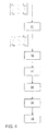
- FIG. 7 shows a disclosed embodiment of a function implemented in a correction module
- FIG. 8 shows an explanation of the functioning or operation of a contrast adjustment module
- FIG. 9 shows a disclosed embodiment of the signal levels of a matrix touch screen when the ball of a thumb is placed onto the matrix touch screen
- FIG. 10 shows a disclosed embodiment of the signal levels shown in FIG. 9 following contrast adjustment by means of a contrast adjustment module as shown in FIG. 8 ;
- FIG. 11 shows a disclosed embodiment of the signal levels of a matrix touch screen when three fingertips are placed onto the matrix touch screen
- FIG. 12 shows a disclosed embodiment of the signal levels shown in FIG. 11 following contrast adjustment by means of a contrast adjustment module as shown in FIG. 8 ;
- FIG. 13 shows a disclosed embodiment of the signal levels shown in FIG. 12 following quadrupling of the pixels by interpolation
- FIG. 14 shows a disclosed embodiment of the signal levels shown in FIG. 13 following fresh contrast adjustment
- FIG. 15 shows a disclosed embodiment of a method for the operator control of a motor vehicle
- FIG. 16 shows a disclosed embodiment of detected touches of a multitouch screen at a sampling time i ⁇ 1;
- FIG. 17 shows a disclosed embodiment of detected touches of a multitouch screen at a sampling time I
- FIG. 18 shows a disclosed embodiment of detected touches of a multitouch screen at a sampling time i and at a sampling time i ⁇ 1;
- FIG. 19 shows a disclosed embodiment of detected touches of a multitouch screen at a sampling time i and at a sampling time i ⁇ 1;
- FIG. 20 shows a disclosed embodiment of a table containing designations of distances
- FIG. 21 shows a disclosed embodiment of associations between detected touches of a multitouch screen at a sampling time i and detected touches of a multitouch screen at a sampling time i ⁇ 1;
- FIG. 22 shows another disclosed embodiment of associations between detected touches of a multitouch screen at a sampling time i and detected touches of a multitouch screen at a sampling time i ⁇ 1;
- FIG. 23 shows a further disclosed embodiment of associations between detected touches of a multitouch screen and a sampling time i and detected touches of a multitouch screen at a sampling time i ⁇ 1;
- FIG. 24 shows yet another disclosed embodiment of associations between identified touches of a multitouch screen and a sampling time i and a detected touches of a multitouch screen at a sampling time i ⁇ 1;
- FIG. 25 shows a disclosed embodiment of a virtual rotary control.
- Disclosed embodiments provide a method for operating a capacitive, matrix touch screen, in particular for use in a motor vehicle, wherein touching the matrix touch screen in the region of a matrix element prompts a signal level associated with the matrix element to be produced, wherein the signal level associated with the matrix element which is produced when the matrix touch screen is touched in the region of the matrix element is modified such that the signal level is increased when this signal level exceeds an upper signal level limit value, in particular at a maximum signal level, is decreased when this signal level is below a lower signal level limit value, particularly at a minimum signal level, and/or is scaled when this signal level is below the upper signal level limit value but exceeds a lower signal level limit value, and wherein the modified signal levels of two adjacent matrix elements are advantageously taken as a basis for determining whether the two matrix elements have been touched as part of a joint two-dimensional touch of the matrix touch screen.
- a matrix element may be a pixel.
- a matrix touch screen may be a matrix touch screen segmented into columns and rows.
- a matrix touch screen may be a matrix touch screen in which the matrix elements or pixels are associated with one row each and one column each.
- a matrix touch screen may be a multitouch screen for detecting the position of at least two simultaneously occurring touches of the multitouch screen.
- At least one disclosed embodiment of a matrix touch screen is the touch input system disclosed in US 2009/0284495 A1, for example, or the touch sensor 110 .
- Another disclosed embodiment of a matrix touch screen is the touch sensor panel 124 disclosed in US 2008/0309629 A1, for example.
- a matrix touch screen may be arranged in a motor vehicle.
- a matrix touch screen may be used for the operator control of the function of a motor vehicle.
- a function of a motor vehicle may be the reception frequency of a radio, the volume of an audible output in the motor vehicle, a tone setting (nature and balance), a selection of a map detail, a title selection, a selection of a destination and/or a temperature setting.
- a function of a motor vehicle may be a function for which a setpoint value from a selection of, in particular continuous, values is intended to be met.
- a function of a motor vehicle may be a function that can be set on an analog basis, in particular following a scale.
- the function of the motor vehicle comprises scrolling through a list.
- the function of the motor vehicle comprises the displacement of a map detail.
- the function of the motor vehicle comprises the scaling of a map detail.
- the function of the motor vehicle comprises the movement of an element presented on the display.
- a signal level associated with a matrix element is not a binary value but rather an analog value or a digitized value which can assume more than two values.
- a signal level may be a digitized value for an analog output variable of a matrix touch screen.
- the region between the upper signal level limit value and the lower signal level limit value is projected onto a region between zero and the maximum possible value of the signal level (maximum signal level).
- maximum signal level Such a projection is shown by way of example in FIG. 8 .
- An upper signal level limit value is not smaller than a lower signal level limit value.
- An upper signal level limit value may be the same as a lower signal limit value.
- a suitable algorithm for determining whether the matrix elements are touched as part of a joint two-dimensional touch of the matrix touch screen is disclosed by the article “A Linear-Time Component-Labeling Algorithm Using Contour Tracing Technique”, Fu Chang, Chun-Jen Chen and Chi-Jen Lu, Institute of Information Science, Academia Sinica, 128 Academia Road, Section 2, Nankang, Taipei 115 Taiwan, www.iis.sinica.edu.tw/ ⁇ fchang/paper/component_labeling_cviu.pdf. The method described in this article presupposes binary values.
- the latter are assigned to a first variable when they are above a particular limit value and are assigned to a second variable when they are not above this limit value.
- the signal levels reduced to binary signals in this manner are then processed by means of the aforementioned algorithm, advantageously only a neighborhood of four being assumed.
- a matrix element below, this may also be a reference to a pseudo matrix element.
- a signal level of a matrix element below, this may also be a reference to a signal level (calculated by interpolation) of a pseudo matrix element.
- the modified signal levels of a matrix element and of (at least, but in particular precisely) four matrix elements adjacent to this matrix element are taken as a basis for determining whether the matrix element and the adjacent matrix elements are touched as part of a joint two-dimensional touch of the matrix touch screen.
- the upper signal level limit value for a matrix element is determined on the basis of the sum of the signal levels of a plurality of matrix elements in the row of the matrix element or the sum of the signal levels of (essentially) all or all essential matrix elements in the row of the matrix element. In yet another disclosed, the upper signal level limit value for a matrix element is determined on the basis of the sum of the signal levels of a plurality of matrix elements in the column of the matrix element or the sum of the signal levels of (essentially) all or all essential matrix elements in the column of the matrix element.
- a plurality of matrix elements in a row or in a column may be a fixed or predetermined number of matrix elements or pixels.
- a plurality of matrix elements in a row or in a column may be a number of matrix elements or pixels which is stipulated independently of the touch of the matrix touch screen.
- a row may be a horizontal arrangement of matrix elements or pixels.
- a column may be a vertical arrangement of matrix elements or pixels.
- the sum of the signal levels is set (essentially) to zero when it is below a limit value.
- the sum of the signal levels is scaled when it exceeds a or the limit value, and yet another disclosed embodiment, the sum of the signal levels is multiplied by a scaling factor when it exceeds a or the limit value.
- the distance of a detected two-dimensional touch of the matrix touch screen at a sampling time from a detected two-dimensional touch of the matrix touch screen at a preceding sampling time is ascertained, with provision advantageously being made for the ascertained distance to be taken as a basis for determining whether the detected two-dimensional touches are part of the same touching movement over the matrix touch screen.
- the distances of the detected two-dimensional touches of the matrix touch screen at a sampling time from the detected two-dimensional touches of the matrix touch screen at a preceding sampling time are ascertained, with provision advantageously being made for the ascertained distances to be taken as a basis for determining whether the detected two-dimensional touches are part of the same touching movement over the matrix touch screen.
- a distance needs to be ascertained particularly from the centroid of the face and/or from another point which defines or describes the center of the touch.
- a preceding sampling time may be the directly preceding sampling time. If the touch of a matrix touch screen is ascertained at the sampling time i, the preceding sampling time may be the sampling time i ⁇ 1.
- sampling time relates to the digitization or the digital capture of touches of the matrix touch screen.
- a touching movement over the matrix touch screen is intended to be translated into a trajectory.
- a trajectory can be used for displacing a graphical element on a display or for identifying a letter, a graphic character or a number, for example.
- touches or the touches are not categorized as part of the same touching movement over the matrix touch screen when the distance between these touches exceeds a limit value.
- the limit value is dependent on the function which is intended to be controlled by means of the touching movement.
- a function may be a function of the motor vehicle.
- a function may be displayed on a display.
- a sampling interval is the interval of time between two sampling times.
- An interpolation factor indicates how many intermediate steps between two sensor lines of the matrix touch screen are used for position finding by interpolation.
- the speed limit value is not greater than 0.25 m/s when the function is the displacement of a graphical element on a display.
- a graphical element for the may be an icon, a virtual operator control element and/or a map or a map detail.
- the speed limit value is 0.25 m/s when the function is the displacement of a graphical element on a display.
- the speed limit value is not greater than 0.5 m/s when the function is handwriting input.
- the speed limit value is 0.5 m/s when the function is handwriting input.
- the speed limit value is not greater than 1 m/s when the function is the scrolling of list entries displayed on a display. In still another disclosed embodiment, the speed limit value is 1 m/s when the function is the scrolling of list entries displayed on a display. In a further disclosed embodiment, the speed limit value is lower when the function is the displacement of a graphical element on a display than when the function is handwriting input. In yet another disclosed embodiment, the speed limit value is lower when the function is the displacement of a graphical element on a display than when the function is the scrolling of list entries displayed on a display. In still another disclosed embodiment, the speed limit value is lower when the function is handwriting input than when the function is the scrolling of list entries displayed on a display. In another disclosed embodiment, the speed limit value is greater than 1 m/s when the function is a swiping movement.
- a touch of the matrix touch screen at a sampling time has that touch of the matrix touch screen at a preceding sampling time that is at the shortest distance from the touch of the matrix touch screen at the sampling time associated with it.
- every touch of the matrix touch screen at a sampling time has that touch of the matrix touch screen at a preceding sampling time that is at the shortest distance from the touch of the matrix touch screen at the sampling time associated with it.
- when a touch of the matrix touch screen at the sampling time has more than one touch of the matrix touch screen at a preceding sampling time associated with it all associations between these touches except for the association at the shortest distance are erased.
- Disclosed embodiments are suitable for use in motor vehicles or for touch screens which are provided in motor vehicles for the operator control of the motor vehicle or for the operator control of functions of the motor vehicle.
- the vibration and the shortest possible visual contact with the touch screen mean that there are, in particular, imprecise and/or two-dimensional and/or multiple touches which result in not insubstantial fuzziness of the input.
- Disclosed embodiments allow better identification of the desired touch to be ensured.
- Disclosed embodiments can be used to detect touches by the ball of a thumb and touches for the operator control of a virtual rotary control on a display in a particularly suitable manner.
- a motor vehicle may be a land vehicle which can be used individually in road traffic.
- Motor vehicles are not limited to land vehicles with an internal combustion engine.
- FIG. 1 shows a disclosed embodiment of a detail from an interior view of a motor vehicle 1 which is shown in a block diagram in FIG. 2 .
- the motor vehicle 1 comprises an operator control apparatus 4 which is arranged on the dashboard 3 next to the steering wheel 2 .
- the operator control apparatus 4 can be used to control a navigation system 23 and also, by way of example, an automatic air conditioning system 24 , an infotainment system 25 and—via a mobile telephone interface 22 —a mobile telephone 21 .
- the operator control apparatus 4 is coupled to a display controller 10 which is connected to the telephone interface 22 , to the navigation system 23 , to the automatic air conditioning system 24 and to the infotainment system 25 by means of a bus system.
- the operator control apparatus 4 comprises—as FIG. 3 shows—a display 12 for presenting variable information and a transparent matrix touch screen 11 which is arranged above the display 12 . Provision may (alternatively or additionally) also be made for the matrix touch screen 11 to be arranged so as to be physically separate from the display 12 .
- the matrix touch screen 11 may thus be arranged in the region of the central console 5 of the motor vehicle 1 .
- the matrix touch screen 11 may also be arranged in the region of a gear lever knob 6 in the motor vehicle 1 .
- the matrix touch screen 11 comprises a matrix-like structure of conductive lines/faces with columns and rows.
- this structure may consist of or comprise ITO faces or fine wires.
- FIG. 4 shows a method implemented in the display controller 10 for processing the output value
- the display controller 10 comprises—as shown in FIG. 5 —a contrast correction module 60 .
- the values I ji denote the signal levels of the relevant matrix elements or pixels in the j-th row and in the i-th column.
- the contrast correction module 60 comprises a vertical projection module 61 and a horizontal projection module 62 for ascertaining what is known as a vertical projection, that is to say
- the contrast correction module 60 also comprises correction modules 63 and 64 which are used to convert the elements of the matrix
- C denotes the elements of the matrix [ C V1 . . . C Vi . . . C Vm ] and the matrix
- I′ max,ji is an input variable into a contrast adjustment module 66 which is used to convert the signal levels
- signal levels I ji which are greater than the upper signal level limit value I′ max,ji are set at a maximum possible signal level MAX.
- Signal levels which are less than a lower signal level limit value I min are set at a minimum value MIN, particularly zero.
- Signal levels I ji which are greater than the lower signal level limit value I min and are less than the upper signal level limit value I′ max,ji are scaled in line with their level to a value between MAX and MIN, with the coarsely hatched region in FIG. 8 being mapped onto the finely hatched region.
- FIG. 9 shows
- FIG. 10 shows
- Step 31 is followed by an optional interpolation step 32 in which interpolation is used, for example, to generate four pseudo matrix elements from a matrix element.
- the interpolation step 32 is optionally followed by a step 33 with a further contrast adjustment, which can be made in conventional fashion or line with the method described with reference to step 31 .
- FIG. 11 , FIG. 12 , FIG. 13 and FIG. 14 illustrate the mode of action of steps 31 to 33 with reference to a touch of the multitouch screen 11 by means of three fingertips, wherein FIG. 11 shows the input signal
- FIG. 12 shows—in the form of a grayscale image—the adjusted signal levels
- FIG. 13 shows—in the form of a grayscale image—the signal levels following the interpolation step 32 and
- FIG. 14 shows—in the form of a grayscale image—the signal levels following fresh contrast adjustment as per step 33 .
- steps 31 , 32 and 33 allow contiguous areas, such as the touches which are respectively associated with a finger or a fingertip, to be detected.
- This detection of contiguous areas takes place in a step 34 by using the algorithm disclosed in the article “A Linear-Time Component-Labeling Algorithm Using Contour Tracing Technique”, Fu Chang, Chun-Jen Chen and Chi-Jen Lu, Institute of Information Science, Academia Sinica, 128 Academia Road, Section 2, Nankang, Taipei 115 Taiwan, www.iis.sinica.edu.tw/ ⁇ fchang/paper/component_labeling_cviu.pdf, with signal levels being assigned to a first variable beforehand when they are above a particular limit value and being assigned to a second variable when they are not above this limit value.
- the signal levels reduced to binary signals in this manner are then processed by means of the aforementioned algorithm, only a neighborhood of four being assumed, however.
- Step 34 is followed by what is known as a tracking step 35 , which is used to detect contiguous movements from touches for different sampling steps.
- FIG. 15 shows a method for implementing this tracking step 35 .
- FIG. 16 and FIG. 17 disclose embodiments of detected touches, with FIG. 16 showing the touches 41 , 42 , 43 of the matrix touch screen 11 at a sampling time i ⁇ 1 and FIG. 17 showing the detected touches 51 and 52 of the matrix touch screen 11 at a sampling time i.
- the method described with reference to FIG. 15 begins with a step 71 , in which the distances of the touches 51 and 52 of the matrix touch screen 11 at the sampling time i from the touches 41 , 42 , 43 of the matrix touch screen 11 at the preceding sampling time i ⁇ 1 are ascertained, as shown by way of example in FIG. 18 and FIG. 19 .
- FIG. 18 and FIG. 19 show the touches 51 and 52 of the matrix touch screen 11 at the sampling time i.
- the touches 41 , 42 , 43 of the matrix touch screen 11 at the sampling time i ⁇ 1 are merely shown in dashes.
- D 11 denotes the distance between the touch 51 of the matrix touch screen 11 at the sampling time i and the touch 41 of the matrix touch screen 11 at the sampling time i ⁇ 1
- D 12 denotes the distance between the touch 51 of the matrix touch screen 11 at the sampling time i and the touch 42 of the matrix touch screen 11 at the sampling time i ⁇ 1
- D 13 denotes the distance between the touch 51 of the matrix touch screen 11 at the sampling time i and the touch 43 of the matrix touch screen 11 at the sampling time i ⁇ 1
- D 21 denotes the distance between the touch 52 of the matrix touch screen 11 at the sampling time i and the touch 41 of the matrix touch screen 11 at the sampling time i ⁇ 1
- D 22 denotes the distance between the touch 52 of the matrix touch screen 11 at the sampling time i and the touch 42 of the matrix touch screen 11 at the sampling time i ⁇ 1
- D 23 denotes the distance between the touch 52 of the matrix touch screen 11 at the sampling time i and the touch 43 of the matrix touch screen 11 at the sampling time i
- FIG. 20 shows a table containing the relevant designations of the distances D 11 , D 12 , D 21 , D 22 and D 23 .
- Step 71 is followed by a step 72 , in which each touch 51 , 52 of the matrix touch screen 11 at the sampling time i has that touch 41 , 42 , 43 of the matrix touch screen 11 at the preceding sampling time i ⁇ 1, that is at the shortest distance D 11 , D 12 , D 23 from the touch 51 , 52 of the matrix touch screen 11 at the sampling time i associated with it.
- the associations are marked in FIG. 21 by the enlarged presentation and the bold text of the relevant numbers. The minimum distances which have been found are therefore the distances D 11 , D 12 and D 23 .
- Step 72 is followed by a test 73 to determine whether, as shown by way of example in FIG. 21 , a touch 51 of the matrix touch screen 11 at the sampling time i has more than one associated touch 41 , 42 of the matrix touch screen 11 at the preceding sampling time i ⁇ 1. If a touch 51 of the matrix touch screen 11 at the sampling time i does have more than one associated touch 41 , 42 of the matrix touch screen 11 at the preceding sampling time i ⁇ 1, all associations between the touches 51 , 41 , 42 apart from the association at the shortest distance D 11 are erased. In the example shown in FIG.
- the loop comprising test 73 and step 74 is executed again, with the value 7, that is to say the association between the touch 52 of the matrix touch screen 11 at the sampling time i and the touch 42 of the matrix touch screen 11 at the sampling time i ⁇ 1, being erased, since the distance D 22 having the value 7 is greater than the distance D 23 having the value 2.
- D max is the limit value
- i is an interpolation factor
- k is the distance between two parallel sensor lines of the matrix touch screen 11 or the real resolution of the matrix touch screen 11
- ⁇ t is the sampling interval
- v max is a speed limit value.
- the speed limit value is
- the association that corresponds to this distance is erased in a step 76 .
- the limit value D max is 9, for example. Therefore, as indicated by way of example in FIG. 24 , a possible association between the touch 52 and the touch 41 would be erased.
- the test 75 is followed by a step 77 in which the touches associated with one another are associated with one and the same touching movement over the matrix touch screen 11 , that is to say a trajectory.
- FIG. 24 shows—the associations between the touches 51 and 41 and the associations between the touches 52 and 43 . That is to say that the touch 51 and the touch 41 are associated with one and the same touching movement over the matrix touch screen 11 .
- the touches 52 and 43 are associated with one and the same touching movement over the matrix touch screen 11 .
- the system therefore detects two touching movements over the matrix touch screen 11 .
- step 34 or step 35 is followed by a step 36 in which the detected two-dimensional touch or the moving touch is classified.
- FIG. 25 discloses an embodiment of such a virtual rotary control 80 which can be presented by means of the display 12 and controlled by means of the multitouch screen 11 .
- reference symbol 85 denotes the hand of a user who is using two fingers to perform a rotary movement over the multitouch screen 11 which, using the method described, can be interpreted as operator control of the rotary control 80 and, in the embodiment described, results in appropriate adjustment of the volume of an audio signal.
- the display controller 10 may have a plurality of processors implemented in it which each execute the method described in FIG. 4 in parallel for a particular number of matrix elements in each case.
Abstract
Description
D max =i·k·Δt·v max,
where Dmax is the limit value, i is an interpolation factor, k is the distance between two parallel sensor lines of the matrix touch screen or the real resolution of the matrix touch screen, Δt is the sampling interval and vmax is a speed limit value. A sampling interval is the interval of time between two sampling times. An interpolation factor indicates how many intermediate steps between two sensor lines of the matrix touch screen are used for position finding by interpolation. By way of example, if provision is made for the center between two sensor lines to be used as a single interpolation value in order to associate a distinct position with a touch, the interpolation factor is 2. If no interpolation is performed, the interpolation factor is equal to 1, i.e. the limit value is advantageously determined or calculated on the basis of the formula
D max =k·Δt·v max.
from the
or a horizontal projection, that is to say
The operation of the
into elements of the matrix
[C V1 . . . C Vi . . . C Vm]
and to convert the elements of the matrix
into elements of the matrix
in line with the function shown in
[C V1 . . . C Vi . . . C Vm]
and the matrix
and P denotes the elements of the matrix
and the matrix
In line with the function shown in
where m is the gradient of a straight line and P0 is an intervention offset.
[C V1 . . . C Vi . . . C Vm]
and the matrix
are input variables into a limit
I′ max,ji =I max −C Vi −C Hj −a·C Vi ·C Hj
where a is a constant and where Imax is a constant, particularly in the magnitude of a standard contrast adjustment.
in line with the algorithm shown in
signal levels Iji which are greater than the upper signal level limit value I′max,ji are set at a maximum possible signal level MAX. Signal levels which are less than a lower signal level limit value Imin are set at a minimum value MIN, particularly zero. Signal levels Iji which are greater than the lower signal level limit value Imin and are less than the upper signal level limit value I′max,ji are scaled in line with their level to a value between MAX and MIN, with the coarsely hatched region in
in the form of a grayscale image and
in the form of a grayscale image. When the ball of a thumb is placed onto the surface of the
in the form of a grayscale image.
following execution of
D max =i·k·Δt·v max,
where Dmax is the limit value, i is an interpolation factor, k is the distance between two parallel sensor lines of the
Claims (8)
Applications Claiming Priority (4)
| Application Number | Priority Date | Filing Date | Title |
|---|---|---|---|
| DE102011009710.4 | 2011-01-29 | ||
| DE201110009710 DE102011009710A1 (en) | 2011-01-29 | 2011-01-29 | Method for operating a matrix touch screen, in particular a touch screen arranged in a motor vehicle |
| DE102011009710 | 2011-01-29 | ||
| PCT/EP2011/005961 WO2012100795A1 (en) | 2011-01-29 | 2011-11-28 | Method for the operator control of a matrix touchscreen |
Publications (2)
| Publication Number | Publication Date |
|---|---|
| US20130307825A1 US20130307825A1 (en) | 2013-11-21 |
| US9069428B2 true US9069428B2 (en) | 2015-06-30 |
Family
ID=45047723
Family Applications (1)
| Application Number | Title | Priority Date | Filing Date |
|---|---|---|---|
| US13/982,325 Active 2032-07-09 US9069428B2 (en) | 2011-01-29 | 2011-11-28 | Method for the operator control of a matrix touchscreen |
Country Status (6)
| Country | Link |
|---|---|
| US (1) | US9069428B2 (en) |
| EP (1) | EP2668557B1 (en) |
| KR (1) | KR101487351B1 (en) |
| CN (1) | CN103329083B (en) |
| DE (1) | DE102011009710A1 (en) |
| WO (1) | WO2012100795A1 (en) |
Families Citing this family (7)
| Publication number | Priority date | Publication date | Assignee | Title |
|---|---|---|---|---|
| GB201200493D0 (en) * | 2012-01-12 | 2012-02-22 | Jaguar Cars | Vehicle test and diagnostics arrangement and method (switch pack actuation) |
| DE102013105507A1 (en) | 2013-05-29 | 2014-12-04 | Dr. Ing. H.C. F. Porsche Aktiengesellschaft | Method and device for operating at least one screen in a vehicle |
| US9098180B1 (en) * | 2013-08-29 | 2015-08-04 | Panasonic Automotive Systems Company Of America, Division Of Panasonic Corporation Of North America | User interface and method for personalized radio station creation |
| KR20150109042A (en) * | 2014-03-19 | 2015-10-01 | 삼성전기주식회사 | Touchscreen apparatus and touch input sensing method |
| JP6552869B2 (en) * | 2014-05-02 | 2019-07-31 | 株式会社半導体エネルギー研究所 | Information processing device |
| FR3049733B1 (en) * | 2016-04-01 | 2018-03-30 | Thales | METHOD FOR SECURELY CONTROLLING A FUNCTION USING A TOUCH SLAB |
| DE102020211794A1 (en) | 2020-09-21 | 2022-03-24 | Volkswagen Aktiengesellschaft | Operating device for a motor vehicle |
Citations (14)
| Publication number | Priority date | Publication date | Assignee | Title |
|---|---|---|---|---|
| DE20102197U1 (en) | 2001-02-08 | 2001-06-13 | Kim Han Sung | Touchscreen with a touch input that confirms the user |
| US6606420B1 (en) | 1999-10-25 | 2003-08-12 | Xerox Corporation | Method and apparatus for digital image darkness control in saturated image structures |
| EP1517228A2 (en) | 2003-09-16 | 2005-03-23 | Smart Technologies, Inc. | Gesture recognition method and touch system incorporating the same |
| US20060161871A1 (en) | 2004-07-30 | 2006-07-20 | Apple Computer, Inc. | Proximity detector in handheld device |
| US7348991B1 (en) * | 2003-04-16 | 2008-03-25 | Silicon Image, Inc. | Video/graphics text mode enhancement method for digitally processed data |
| DE60220933T2 (en) | 2001-10-03 | 2008-04-03 | 3M Innovative Properties Co., St. Paul | METHOD FOR DISTINCTING SIMULTANEOUS TOUCH ENTRIES |
| US20080158145A1 (en) | 2007-01-03 | 2008-07-03 | Apple Computer, Inc. | Multi-touch input discrimination |
| US20080309629A1 (en) | 2007-06-13 | 2008-12-18 | Apple Inc. | Bottom up watershed dataflow method and region-specific segmentation based on historic data |
| WO2009007704A1 (en) | 2007-07-12 | 2009-01-15 | Qrg Limited | Two-dimensional touch panel |
| US20090095540A1 (en) | 2007-10-11 | 2009-04-16 | N-Trig Ltd. | Method for palm touch identification in multi-touch digitizing systems |
| US20090284491A1 (en) | 2008-05-16 | 2009-11-19 | Htc Corporation | Method for filtering signals of touch sensitive device |
| US20090284495A1 (en) | 2008-05-14 | 2009-11-19 | 3M Innovative Properties Company | Systems and methods for assessing locations of multiple touch inputs |
| WO2009154596A1 (en) | 2008-06-20 | 2009-12-23 | Hewlett-Packard Development Company, L.P. | Method and system for efficient video processing |
| US20110216016A1 (en) * | 2010-03-08 | 2011-09-08 | Plantronics, Inc. | Touch Sensor With Active Baseline Tracking |
Family Cites Families (4)
| Publication number | Priority date | Publication date | Assignee | Title |
|---|---|---|---|---|
| US7663607B2 (en) * | 2004-05-06 | 2010-02-16 | Apple Inc. | Multipoint touchscreen |
| KR101077854B1 (en) * | 2008-05-22 | 2011-10-31 | (주)멜파스 | Method and apparatus for sensing multiple touch-inputs |
| US8154529B2 (en) * | 2009-05-14 | 2012-04-10 | Atmel Corporation | Two-dimensional touch sensors |
| CN101840295A (en) * | 2010-03-10 | 2010-09-22 | 敦泰科技(深圳)有限公司 | Multipoint touch detection method of capacitance touch screen |
-
2011
- 2011-01-29 DE DE201110009710 patent/DE102011009710A1/en not_active Withdrawn
- 2011-11-28 CN CN201180065322.9A patent/CN103329083B/en active Active
- 2011-11-28 KR KR1020137013634A patent/KR101487351B1/en active IP Right Grant
- 2011-11-28 EP EP11788384.3A patent/EP2668557B1/en active Active
- 2011-11-28 US US13/982,325 patent/US9069428B2/en active Active
- 2011-11-28 WO PCT/EP2011/005961 patent/WO2012100795A1/en active Application Filing
Patent Citations (14)
| Publication number | Priority date | Publication date | Assignee | Title |
|---|---|---|---|---|
| US6606420B1 (en) | 1999-10-25 | 2003-08-12 | Xerox Corporation | Method and apparatus for digital image darkness control in saturated image structures |
| DE20102197U1 (en) | 2001-02-08 | 2001-06-13 | Kim Han Sung | Touchscreen with a touch input that confirms the user |
| DE60220933T2 (en) | 2001-10-03 | 2008-04-03 | 3M Innovative Properties Co., St. Paul | METHOD FOR DISTINCTING SIMULTANEOUS TOUCH ENTRIES |
| US7348991B1 (en) * | 2003-04-16 | 2008-03-25 | Silicon Image, Inc. | Video/graphics text mode enhancement method for digitally processed data |
| EP1517228A2 (en) | 2003-09-16 | 2005-03-23 | Smart Technologies, Inc. | Gesture recognition method and touch system incorporating the same |
| US20060161871A1 (en) | 2004-07-30 | 2006-07-20 | Apple Computer, Inc. | Proximity detector in handheld device |
| US20080158145A1 (en) | 2007-01-03 | 2008-07-03 | Apple Computer, Inc. | Multi-touch input discrimination |
| US20080309629A1 (en) | 2007-06-13 | 2008-12-18 | Apple Inc. | Bottom up watershed dataflow method and region-specific segmentation based on historic data |
| WO2009007704A1 (en) | 2007-07-12 | 2009-01-15 | Qrg Limited | Two-dimensional touch panel |
| US20090095540A1 (en) | 2007-10-11 | 2009-04-16 | N-Trig Ltd. | Method for palm touch identification in multi-touch digitizing systems |
| US20090284495A1 (en) | 2008-05-14 | 2009-11-19 | 3M Innovative Properties Company | Systems and methods for assessing locations of multiple touch inputs |
| US20090284491A1 (en) | 2008-05-16 | 2009-11-19 | Htc Corporation | Method for filtering signals of touch sensitive device |
| WO2009154596A1 (en) | 2008-06-20 | 2009-12-23 | Hewlett-Packard Development Company, L.P. | Method and system for efficient video processing |
| US20110216016A1 (en) * | 2010-03-08 | 2011-09-08 | Plantronics, Inc. | Touch Sensor With Active Baseline Tracking |
Non-Patent Citations (5)
| Title |
|---|
| Chang et al.; A linear-time component-labeling algorithm using contour tracing technique; Computer Vision and Image Understanding; 2003; 15 pages. |
| International Preliminary Report on Patentability for International Patent Application No. PCT/EP2011/005961; Jul. 30, 2013. |
| Search Report for German Patent Application No. 10 2011 009 710.4; Jun. 29, 2011. |
| Search Report for International Patent Application No. PCT/EP2011/005961; Apr. 19, 2012. |
| U.S. Appl. No. 11/928,629, filed Oct. 30 2007. |
Also Published As
| Publication number | Publication date |
|---|---|
| US20130307825A1 (en) | 2013-11-21 |
| EP2668557B1 (en) | 2018-08-08 |
| EP2668557A1 (en) | 2013-12-04 |
| KR20130109165A (en) | 2013-10-07 |
| KR101487351B1 (en) | 2015-01-29 |
| WO2012100795A1 (en) | 2012-08-02 |
| CN103329083B (en) | 2016-03-16 |
| CN103329083A (en) | 2013-09-25 |
| DE102011009710A1 (en) | 2012-08-02 |
Similar Documents
| Publication | Publication Date | Title |
|---|---|---|
| US9069428B2 (en) | Method for the operator control of a matrix touchscreen | |
| US9477315B2 (en) | Information query by pointing | |
| US8606519B2 (en) | Navigation system, particularly for a motor vehicle | |
| US8284168B2 (en) | User interface device | |
| US8760410B2 (en) | Apparatus and method for improvement of usability of touch screen | |
| US8456445B2 (en) | Touch screen and method for adjusting screen objects | |
| US9956878B2 (en) | User interface and method for signaling a 3D-position of an input means in the detection of gestures | |
| US20090128516A1 (en) | Multi-point detection on a single-point detection digitizer | |
| US20110187651A1 (en) | Touch screen having adaptive input parameter | |
| CN106687905B (en) | Tactile sensation control system and tactile sensation control method | |
| JP2018025916A (en) | On-vehicle operation device | |
| US9739995B2 (en) | Operating system and method for displaying an operating area | |
| JP6177660B2 (en) | Input device | |
| JP2012099005A (en) | Input device, input method, and input program | |
| US20170123534A1 (en) | Display zoom operation with both hands on steering wheel | |
| US10114474B2 (en) | Method and device for operating an input device | |
| US20150378504A1 (en) | Operation detective device | |
| CN106926697B (en) | Display system and display device for vehicle | |
| US10690509B2 (en) | Display system and method for operating a display system in a transportation vehicle having at least one first and one second display surface | |
| US20190318711A1 (en) | Electronically Damped Touch Screen Display | |
| US11602992B2 (en) | Method for displaying points of interest on a digital map | |
| JP2020060930A (en) | Input device | |
| WO2019131926A1 (en) | Target selecting device | |
| JP2015176471A (en) | Display control device, display control method and program for display control device | |
| JP2014191818A (en) | Operation support system, operation support method and computer program |
Legal Events
| Date | Code | Title | Description |
|---|---|---|---|
| AS | Assignment |
Owner name: VOLKSWAGEN AG, GERMANY Free format text: ASSIGNMENT OF ASSIGNORS INTEREST;ASSIGNORS:CZELNIK, MARK PETER;BENDEWALD, LENNART;SIGNING DATES FROM 20130403 TO 20130408;REEL/FRAME:030894/0518 |
|
| STCF | Information on status: patent grant |
Free format text: PATENTED CASE |
|
| MAFP | Maintenance fee payment |
Free format text: PAYMENT OF MAINTENANCE FEE, 4TH YEAR, LARGE ENTITY (ORIGINAL EVENT CODE: M1551); ENTITY STATUS OF PATENT OWNER: LARGE ENTITY Year of fee payment: 4 |
|
| MAFP | Maintenance fee payment |
Free format text: PAYMENT OF MAINTENANCE FEE, 8TH YEAR, LARGE ENTITY (ORIGINAL EVENT CODE: M1552); ENTITY STATUS OF PATENT OWNER: LARGE ENTITY Year of fee payment: 8 |