US9372576B2 - Image jaggedness filter for determining whether to perform baseline calculations - Google Patents
Image jaggedness filter for determining whether to perform baseline calculations Download PDFInfo
- Publication number
- US9372576B2 US9372576B2 US12/238,333 US23833308A US9372576B2 US 9372576 B2 US9372576 B2 US 9372576B2 US 23833308 A US23833308 A US 23833308A US 9372576 B2 US9372576 B2 US 9372576B2
- Authority
- US
- United States
- Prior art keywords
- touch sensor
- predetermined threshold
- jaggedness
- sensor outputs
- positive
- Prior art date
- Legal status (The legal status is an assumption and is not a legal conclusion. Google has not performed a legal analysis and makes no representation as to the accuracy of the status listed.)
- Active, expires
Links
- 238000004364 calculation method Methods 0.000 title description 3
- 230000000737 periodic effect Effects 0.000 claims abstract description 54
- 238000000034 method Methods 0.000 claims description 16
- 238000012935 Averaging Methods 0.000 claims 2
- 230000033001 locomotion Effects 0.000 abstract description 55
- XLYOFNOQVPJJNP-UHFFFAOYSA-N water Substances O XLYOFNOQVPJJNP-UHFFFAOYSA-N 0.000 abstract description 18
- 210000003811 finger Anatomy 0.000 description 23
- 238000013519 translation Methods 0.000 description 11
- 230000000694 effects Effects 0.000 description 8
- 239000002609 medium Substances 0.000 description 8
- 238000000926 separation method Methods 0.000 description 6
- 230000008859 change Effects 0.000 description 5
- 238000001514 detection method Methods 0.000 description 5
- 230000006870 function Effects 0.000 description 5
- 230000002093 peripheral effect Effects 0.000 description 5
- 210000003813 thumb Anatomy 0.000 description 4
- 230000003111 delayed effect Effects 0.000 description 3
- 230000003287 optical effect Effects 0.000 description 3
- 238000012545 processing Methods 0.000 description 3
- 230000009471 action Effects 0.000 description 2
- 230000006978 adaptation Effects 0.000 description 2
- 230000008901 benefit Effects 0.000 description 2
- 238000013461 design Methods 0.000 description 2
- 238000010586 diagram Methods 0.000 description 2
- 238000012986 modification Methods 0.000 description 2
- 230000004048 modification Effects 0.000 description 2
- 238000010606 normalization Methods 0.000 description 2
- 230000004044 response Effects 0.000 description 2
- 239000006163 transport media Substances 0.000 description 2
- 239000013598 vector Substances 0.000 description 2
- 241000699670 Mus sp. Species 0.000 description 1
- 238000009825 accumulation Methods 0.000 description 1
- 230000008602 contraction Effects 0.000 description 1
- 230000007423 decrease Effects 0.000 description 1
- 230000007613 environmental effect Effects 0.000 description 1
- 238000001704 evaporation Methods 0.000 description 1
- 230000010354 integration Effects 0.000 description 1
- 230000001788 irregular Effects 0.000 description 1
- 230000007246 mechanism Effects 0.000 description 1
- 238000004091 panning Methods 0.000 description 1
- 238000012805 post-processing Methods 0.000 description 1
- 230000000644 propagated effect Effects 0.000 description 1
- 239000004065 semiconductor Substances 0.000 description 1
- 230000000638 stimulation Effects 0.000 description 1
- 230000001629 suppression Effects 0.000 description 1
Images


Classifications
-
- G—PHYSICS
- G06—COMPUTING; CALCULATING OR COUNTING
- G06F—ELECTRIC DIGITAL DATA PROCESSING
- G06F3/00—Input arrangements for transferring data to be processed into a form capable of being handled by the computer; Output arrangements for transferring data from processing unit to output unit, e.g. interface arrangements
- G06F3/01—Input arrangements or combined input and output arrangements for interaction between user and computer
- G06F3/03—Arrangements for converting the position or the displacement of a member into a coded form
- G06F3/041—Digitisers, e.g. for touch screens or touch pads, characterised by the transducing means
- G06F3/0416—Control or interface arrangements specially adapted for digitisers
- G06F3/0418—Control or interface arrangements specially adapted for digitisers for error correction or compensation, e.g. based on parallax, calibration or alignment
-
- G—PHYSICS
- G06—COMPUTING; CALCULATING OR COUNTING
- G06F—ELECTRIC DIGITAL DATA PROCESSING
- G06F3/00—Input arrangements for transferring data to be processed into a form capable of being handled by the computer; Output arrangements for transferring data from processing unit to output unit, e.g. interface arrangements
- G06F3/01—Input arrangements or combined input and output arrangements for interaction between user and computer
- G06F3/048—Interaction techniques based on graphical user interfaces [GUI]
- G06F3/0487—Interaction techniques based on graphical user interfaces [GUI] using specific features provided by the input device, e.g. functions controlled by the rotation of a mouse with dual sensing arrangements, or of the nature of the input device, e.g. tap gestures based on pressure sensed by a digitiser
- G06F3/0488—Interaction techniques based on graphical user interfaces [GUI] using specific features provided by the input device, e.g. functions controlled by the rotation of a mouse with dual sensing arrangements, or of the nature of the input device, e.g. tap gestures based on pressure sensed by a digitiser using a touch-screen or digitiser, e.g. input of commands through traced gestures
- G06F3/04883—Interaction techniques based on graphical user interfaces [GUI] using specific features provided by the input device, e.g. functions controlled by the rotation of a mouse with dual sensing arrangements, or of the nature of the input device, e.g. tap gestures based on pressure sensed by a digitiser using a touch-screen or digitiser, e.g. input of commands through traced gestures for inputting data by handwriting, e.g. gesture or text
Definitions
- This relates to touch sensor panels used as input devices for computing systems, and more particularly, to the normalization and post-processing of touch sensor data.
- Touch screens are becoming increasingly popular because of their ease and versatility of operation as well as their declining price.
- Touch screens can include a touch sensor panel, which can be a clear panel with a touch-sensitive surface.
- the touch sensor panel can be positioned partially or completely in front of a display screen, or integrated partially or entirely within the display screen, so that at least a portion of the touch-sensitive surface covers at least a portion of the viewable area of the display screen.
- Touch screens can allow a user to make selections and move a cursor by simply touching the display screen via a finger or stylus.
- the touch screen can recognize the touch and position of the touch on the display screen, and the computing system can interpret the touch and thereafter perform an action based on the touch event.
- Touch sensor panels can be capable of detecting either single-touch events or multiple touch events, an example of which is described in Applicant's co-pending U.S. application Ser. No. 11/649,998 entitled “Proximity and Multi-Touch Sensor Detection and Demodulation,” filed on Jan. 3, 2007, the contents of which are incorporated by reference herein in their entirety for all purposes.
- the sensor output values can be calibrated or normalized by using offset values to compensate the raw no-touch output values for each sensor in the panel so that all sensor output values are normalized to approximately the same value.
- a periodic local baseline offset adjustment algorithm can then be employed to locally update the sensor offset values to account for variables such as temperature drift.
- the periodic local baseline offset adjustment algorithm can generate inaccurate normalized results.
- factors such as temperature changes can rapidly skew the normalized sensor output values.
- it can be difficult to clearly identify and lock onto a particular dominant motion component as a preliminary step in recognizing a particular gesture.
- This relates to an image jaggedness filter that can be used to detect the presence of ungrounded objects such as water droplets or coins on a touch sensor panel, and delay periodic local offset adjustments until these objects have largely disappeared. To do otherwise could produce inaccurate normalized sensor output values.
- This also relates to the application of a global baseline offset to quickly normalize the sensor output values to account for conditions such as rapid temperature changes. Background pixels not part of any touch regions can be used to detect changes to no-touch sensor output values and compute a global baseline offset accordingly.
- This also relates to the use of motion dominance ratios and axis domination confidence values to improve the accuracy of locking onto dominant motion components as part of gesture recognition.
- FIGS. 1 a -1 c illustrate an exemplary periodic local baseline adjustment for a single row of pixels in a touch sensor panel according to embodiments of the invention.
- FIG. 2 a illustrates an exemplary touch sensor panel having water droplets on its touch surface and the resulting touch image having a high spatial frequency.
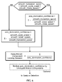
- FIG. 2 b illustrates an exemplary flow diagram of the use of the image jaggedness filter according to one embodiment of this invention.
- FIG. 3 illustrates an exemplary image of touch on touch sensor panel showing how a global baseline offset can be determined according to one embodiment of this invention.
- FIG. 4 a illustrates the computation of an exemplary periodic global baseline offset adjustment value for a single row of pixels (sensors) A-G in a touch sensor panel according to embodiments of the invention.
- FIG. 4 b illustrates an exemplary plot of the overall offset value for a single sensor over time including the total contributions of a local baseline offset and the contribution of a global baseline offset according to one embodiment of this invention.
- FIG. 4 c illustrates an exemplary flowchart or algorithm for implementing the global baseline offset algorithm according to embodiments of the invention.
- FIG. 4 d illustrates an exemplary plot of the overall offset value for a single sensor over time wherein the global baseline offset value is applied to the sensor offset value gradually according to embodiments of the invention.
- FIG. 5 illustrates an exemplary motion component dominance algorithm that can be implemented by a processor executing firmware according to embodiments of the invention.
- FIG. 6 illustrates an exemplary algorithm for computing an axis_domination_confidence value that can be implemented by a processor executing firmware according to embodiments of the invention.
- FIG. 7 illustrates an exemplary computing system operable with a touch sensor panel to implement the image jaggedness filter, global baseline offset, and motion component dominance factors according to one embodiment of this invention.
- FIG. 8 a illustrates an exemplary mobile telephone that can include a touch sensor panel and computing system for implementing the image jaggedness filter, global baseline offset, and motion component dominance factors according to one embodiment of this invention.
- FIG. 8 b illustrates an exemplary digital media player that can include a touch sensor panel and computing system for implementing the image jaggedness filter, global baseline offset, and motion component dominance factors according to one embodiment of this invention.
- FIG. 8 c illustrates an exemplary personal computer that can include a touch sensor panel and computing system for implementing the image jaggedness filter, global baseline offset, and motion component dominance factors according to one embodiment of this invention.
- This relates to an image jaggedness filter that can be used to detect the presence of ungrounded objects such as water droplets or coins, and delay periodic local baseline offset adjustments until these objects have largely disappeared. To do otherwise could produce inaccurate normalized sensor output values.
- This also relates to the application of a global baseline offset to quickly modify the sensor offset values to account for conditions such as rapid temperature changes. Background pixels not part of any touch regions can be used to detect changes to no-touch sensor output values and compute the global baseline offset accordingly.
- This also relates to the use of motion dominance ratios and axis domination confidence values to improve the accuracy of locking onto dominant motion components as part of gesture recognition.
- touch sensor panel output values can be calibrated using offset values to adjust the raw no-touch output values for each sensor in the panel so that all touch sensor panel output values are normalized to approximately the same value.
- offset values can be employed.
- FIGS. 1 a -1 c illustrate an exemplary periodic local baseline adjustment for a single row of pixels (sensors) A-G in a touch sensor panel according to embodiments of the invention. Although not shown, it should be understood that each row in the touch sensor panel can also be subject to this periodic local baseline adjustment.
- the periodic local baseline offset adjustment algorithm can increment or decrement individual sensor offset values by one count or unit, or some small value to provide periodic fine-tuning of the offsets to track temperature drift or other shifts in the sensor output values.
- a no-touch scan of the sensor panel is performed after a dynamic adjustment time interval has passed, and raw sensor output values 108 are obtained.
- the adjustment time interval is generally much longer than the frame rate (the time it takes to scan the entire sensor panel one time).
- Previously computed offset values for each sensor are then subtracted from the measured raw sensor output values 108 to normalize them. Ideally, as shown in FIG. 1 a , the subtraction results in all normalized sensor output values being equal to the same baseline value 112 .
- some of the normalized sensor output values 114 shift due to a change in some condition such as a temperature increase, for example, after subtraction of the offset values 110 -A through 110 -G, some of the normalized sensor output values may be equal to some value other than baseline value 112 , such as value 116 in FIG. 1 b .
- all sensors having normalized sensor output values that are positive and negative as compared to the baseline 112 are identified. (In the example of FIG.
- the normalized sensor values for sensors B-E and G are positive.
- their corresponding offset values are incremented by P, where P may be one count, or a small value, or a percentage of the positive value.
- P represents the full difference between value 116 and the original baseline 112 , but it should be understood that if P represents less than the full difference between value 116 and the original baseline 112 , multiple periodic local baseline offset adjustments can eventually take up the full difference.
- Q may be one count, or a small value, or a percentage of the negative value. The algorithm waits the duration of an adjustment period before scanning the panel again.
- the normalized sensor output values should be closer to the original baseline 112 .
- the offset adjustment value P represented the full difference between value 116 and the original baseline 112
- the normalized sensor output values equal the original baseline 112 .
- the predicted negative pixel value for any particular pixel can be computed by summing up the touch output values for pixels in the drive line of the particular pixel being considered, summing up the touch output values for pixels in the sense line of the particular pixel being considered, and then multiplying these two sums.
- a scaled function of the predicted negative pixel value can then be added to the measured touch output value for the pixel to compensate for artificially negative readings.
- state-of-the-art touch sensor panels can have a greater incidence of negative pixels than previous touch sensor panels.
- negative pixels can appear more frequently due to the expected frequent usage of unplugged notebook computers, which can cause a higher incidence of touches by ungrounded objects.
- Water droplets on a touch sensor panel can also appear as ungrounded objects. On trackpads, where user fingers and palms are often touching (sometimes inadvertently) the panel, water droplets can easily get smeared. Therefore, if the possible presence of water droplets can be detected, it would be preferable to hold off on any periodic local baseline offset adjustment until the water has dried off, because of the likely existence of corrupting negative pixels.
- a jaggedness/irregularity filter can be used, as described in U.S. application Ser. No. 11/619,490 entitled “Irregular Input Identification,” now U.S. Pat. No. 8,269,727, and U.S. application Ser. No. 11/756,211 entitled “Multi-touch Input Discrimination,” now U.S. Pat. No. 8,130,203, both of which are incorporated by reference herein in their entirety for all purposes.
- This jaggedness/irregularity filter can be used to find touch images having a high spatial frequency, such as those caused by water droplets.
- FIG. 2 a illustrates an exemplary touch sensor panel 200 having water droplets 202 on its touch surface.
- the sensors in row 204 can generate touch outputs as shown in plot 106 .
- Plot 206 shows that water droplets 202 , being ungrounded, can generate raw touch sensor output values having a high spatial frequency (a high frequency of occurrence of touch images in space), a certain jaggedness in the captured image, and a number of positive and negative pixels.
- a similar plot can be obtained for every row and column in touch sensor panel 200 .
- FIG. 2 b illustrates an exemplary flow diagram of the use of the image jaggedness filter according to embodiments of the invention.
- a jaggedness measure can be obtained at 208 .
- the jaggedness/irregularity filter as mentioned above can be applied to all rows and columns to generate a jaggedness measure for the entire image.
- the jaggedness measure for all rows and columns can be averaged and normalized.
- a spatial Fourier transform can be used.
- a moderate (relatively even) mix of negative and positive pixels are found or are within a particular mix threshold at 210 , and a certain jaggedness threshold is exceeded at 212 , indicating the presence of numerous poorly grounded objects such as water droplets, then the next periodic local baseline offset adjustment can be skipped at 214 .
- a “moderate” mix of negative and positive pixels may be defined as having percentages of negative and positive pixels are within 40% of each other ⁇ 30% and 70%.
- the jaggedness threshold could be set to 0.5.
- the jaggedness threshold is not exceeded at 212 , but the number of positive and negative pixels is changing rapidly at 216 (which can occur when water droplets are evaporating), periodic local baseline offset adjustments can also be suppressed at 214 .
- the sums of the negative and positive pixels can be passed though a (mathematical) low pass filter (LFP) that produces an auto-regressive average. Instantaneous values can then be subtracted from the average. If the difference is high (greater than a predetermined threshold, such as the instantaneous value being more than 25% different from the computed average), this indicates a large change in the number of negative or positive pixels sufficient to suppress periodic local baseline offset adjustments.
- LFP low pass filter
- next periodic local baseline offset adjustment can occur as scheduled at 218 (including the suppression of an initial baseline capture if fingers are detected at startup, as disclosed in U.S. application Ser. No. 11/650,112 entitled “Periodic Sensor Panel Baseline Adjustment,” the contents of which are incorporated by reference herein in their entirety for all purposes).
- the jaggedness algorithm may only recognize that the jaggedness measure has exceeded a threshold—it does not see actual negative and positive pixels, so it cannot determine that there are few negative pixels remaining.
- periodic local baseline offset adjustments can be performed at 218 .
- the increment/decrement rate of the adaptation algorithm can be sped up, so that the positive pixels are compensated more quickly and the effect is reduced.
- a global baseline offset can be applied to the offset values for all pixels.
- the global baseline offset can be used to effect changes much more quickly than the periodic local baseline offset adjustment algorithm to compensate for large temperature changes or the effects of other global conditions.
- the full amount of this global baseline offset can be immediately applied to the offset values for all pixels.
- the offset values for all pixels can be incremented or decremented gradually over time (but more often than the individual pixels can be incremented or decremented using local baseline offset adjustments), until the full amount of the global baseline offset has been applied.
- FIG. 3 illustrates an exemplary image of touch on touch sensor panel 300 showing how a global baseline offset value can be determined according to embodiments of the invention.
- unions of adjacent or nearby patches can be determined (see 302 and 304 ).
- any number of methods can be used, such as computing the centroids of the patches and grouping together those pixels whose centroids are closest together.
- the union of those patches can be formed based on the touch sensor output values within the patches. For example, for any two grouped patches, all pixels within those two patches having touch sensor output values above a certain threshold can be considered part of the union.
- These union areas can be blocked out from subsequent calculations so that only background pixels 306 remain. In other embodiments, unions need not be formed, and only the patches themselves can be excluded from the background pixels.
- An average of all or a portion of the background pixels 306 can then be computed, and this average can then used to globally modify the offset values for all pixels in the touch sensor panel. Because the background pixels 306 are untouched, the average of their untouched output values can provide an indication of rapid changes to the pixel outputs due to factors such as temperature. This average, or some adjustment value that is a function of this average, can then be added to or subtracted from the current sensor baseline to compute the global baseline offset value. This global baseline offset value can then be added to the current offset values for every pixel in the touch sensor panel to effect a global adjustment of the offset values. In some embodiments, this global baseline offset value can be applied immediately to the current offset values for every pixel.
- the current offset values can be incremented or decremented gradually until the full global baseline offset values has been applied.
- the global baseline offset value can optionally decay to zero over time.
- FIG. 4 a illustrates the computation of an exemplary periodic global baseline offset value for a single row of pixels (sensors) A-G in a touch sensor panel according to embodiments of the invention. Although not shown, it should be understood that each row in the touch sensor panel can be involved in the computation of this global baseline offset value.
- current no-touch (i.e. background) raw sensor output values 408 have risen substantially and in a fairly uniform manner from previous no-touch raw sensor output values 420 due to a change in some condition such as a temperature increase.
- subtracting of the previous sensor offset values 410 -A through 410 -G from the current raw sensor output values 408 results in normalized values 416 well above the original baseline 412 , which can create errors in touch detection and interpretation.
- an average of the background pixels can first be computed. In the example of FIG. 4 a , the average is shown at 422 .
- the difference between this average and the original baseline 412 can be computed as the global baseline offset value 424 .
- This global baseline offset value 424 can then be added to the previous sensor offset values 410 -A through 410 -G to produce updated sensor offset values and effect a global adjustment of the offset values.
- FIG. 4 b illustrates an exemplary plot of the overall offset value 400 for a single sensor over time including the total contributions of a local baseline offset 404 and the contribution of a global baseline offset 402 according to embodiments of the invention.
- the offset value 400 , global baseline offset value 402 , and the total contribution of the local baseline offset value 404 start near zero at 406 , indicating that the raw no-touch sensor output value for that sensor is approximately equal to the desired baseline value.
- the full amount of the calculated global baseline offset value 402 can be immediately added to the sensor offset value, causing the overall sensor offset value 400 to increase rapidly to a value 410 equal to the difference between the average of the background pixels and the original baseline as described above.
- the global baseline offset value 402 can then decay back to zero over time at 412 to ensure that the offset value does not get excessively large or small due to unintended artifacts of the algorithm.
- the local baseline offset adjustment algorithm described above can periodically incrementally increase the overall offset value 400 as the global baseline offset value 402 is decaying. Although each increment to the overall offset value 400 made by the local baseline offset adjustment algorithm is small, the total contribution of the local baseline offset value 404 gradually increases over time, as shown at 414 in FIG. 4 b.
- FIG. 4 c illustrates an exemplary flowchart or algorithm for implementing the global baseline offset algorithm as described above according to embodiments of the invention.
- FIG. 4 d illustrates an exemplary plot of the overall offset value 400 for a single sensor over time wherein the global baseline offset value is applied to the sensor offset value gradually according to embodiments of the invention.
- the global baseline offset value 402 can be incrementally added to the sensor offset value, causing the overall sensor offset value 400 to increase gradually to a value 410 equal to the difference between the average of the background pixels and the original baseline as described above. It should be noted that although the global baseline offset value is applied incrementally, the increment period can be much faster than the local baseline offset adjustment described above.
- the global baseline offset value 402 can then decay back to zero over time at 412 to ensure that the offset value does not get excessively large or small due to unintended artifacts of the algorithm.
- motion components can be extracted.
- motion components can include the X component, the Y component, a scale (zoom) component (the dot product of the two finger motion vectors), and a rotate component (the cross product of the two finger motion vectors).
- the extracted motion components can provide for two types of control. “Integral control” is defined herein as providing all four degrees of freedom (the ability to control all axes at once). “Separable control” is more limited, and separates motion between either (1) X-Y scrolling as a set, (2) zoom, or (3) rotate (i.e. one axis).
- FIG. 5 illustrates an exemplary motion component dominance algorithm 500 that can be implemented by a processor executing firmware according to embodiments of the invention.
- motion components such as the x-direction velocity (Vx), y-direction velocity (Vy), rotational velocity (Vr), and scaling velocity (Vs) can be extracted at 504 .
- embodiments of the invention can lock onto the first component (axis) with significant motion, and ignore the others. For example, if significant X-Y scrolling is detected first, subsequently detected zooming motions may be ignored until liftoff of the fingers.
- smooth_translation_speed value includes Vx and Vy because of the desire to lock onto scrolling as a whole, not just the X and Y components. Of these three values, the dominant (largest) computed speed can be used, while the others can be ignored (zeroed or clipped out).
- the three raw values described above can be utilized in conjunction with two new parameters, scale_dominance_ratio (SDR) and rotate_dominance_ratio (RDR), which can be used to apply weights to the various motion components and set a balance point for the motions so that a particular component can be locked onto more accurately.
- SDR scale_dominance_ratio
- RDR rotate_dominance_ratio
- the SDR and RDR values can be established after the various finger contacts are identified at 508 .
- the SDR and RDR values computed at 510 can be based on whether the detected contacts are identified as fingers and/or thumbs.
- the SDR and RDR values can be set to high values (e.g. 2.5) so that the Smooth_scale_speed or the Smooth_rotate_speed values dominate the Smooth_translation_speed value.
- the SDR and RDR values can be set to lower values to ensure that the Smooth_translation_speed value dominates.
- the multiple-finger, no-thumb SDR value can further be a function of the horizontal separation of the fingers, because it can be more likely that a user is performing a translation or scroll operation when the fingers are close together, but more likely that a user is performing a two finger scaling operation when the fingers have a greater separation.
- the SDR can be set to 0.25 if the finger separation is between 0 and 3 cm, can vary from 0.25 to 1.25 if the separation is from 3-6 cm, and can be set to 1.25 for separations greater than 6 cm.
- an exception can be created for the SDR during a two-finger top-to-bottom translation because of the tendency for a user's fingers to draw together during the translation.
- the movement of the fingers towards each other during the translation should not be interpreted as a scaling operation. To prevent this, if a downward translation is detected plus a scale contraction, then the SDR can be maintained at 0.25, even if the two finger separation distance is high.
- an axis_domination_confidence value can be computed to provide a representation of the unambiguousness of the motion component to be locked onto.
- FIG. 6 illustrates an exemplary algorithm 600 for computing an axis_domination_confidence value that can be implemented by a processor executing firmware according to embodiments of the invention. If smooth_translation_speed ⁇ (smooth_scale_speed+smooth_rotate_speed) at 602 , then
- axis_domination ⁇ _confidence 1 - smooth ⁇ _ ⁇ translation ⁇ _ ⁇ speed ( smooth_scale ⁇ _speed + smooth_rotate ⁇ _speed ) . at 604 . Otherwise, at 606 ,
- axis_domination ⁇ _confidence 1 - ( smooth_scale ⁇ _speed + smooth_rotate ⁇ _speed ) smooth ⁇ _ ⁇ translation ⁇ _ ⁇ speed .
- the axis_domination_confidence value as calculated above can be normalized to be between [0,1], where values approaching 1 represent a pure translation (and therefore there is high confidence in locking on to the X-Y motion components) and values approaching 0 indicate that the translation amount is about equal to the scale and rotation amount (and therefore low confidence in locking on to any motion component).
- the motion component locking decision can be delayed by an amount proportional to the inverse of the axis_domination_confidence value at 608 .
- the value is high, indicating high confidence, there can be little or no delay.
- the locking decision can be delayed to allow for the motion components to become less ambiguous.
- the axis_domination_confidence value (or the square of this value) can be multiplied by any non-clipped motion components (see, e.g., equations (A) and (B) above) at 610 .
- Embodiments of the invention described above can be implemented, for example, using touch sensor panels of the types described in U.S. application Ser. No. 11/650,049 entitled “Double-Sided Touch Sensitive Panel and Flex Circuit Bonding.”
- Sense channels of the types described in U.S. application Ser. No. 11/649,998 entitled “Proximity and Multi-Touch Sensor Detection and Demodulation” can be used, for example, to detect touch and hover events.
- the resulting image of touch can be further processed to determine the location of the touch events, the identification of finger contacts, and the identification of gestures as described, for example, in U.S. application Ser. No. 11/428,522 entitled “Identifying Contacts on a Touch Surface,” U.S. application Ser.
- FIG. 7 illustrates exemplary computing system 700 that can include one or more of the embodiments of the invention described above.
- Computing system 700 can include one or more panel processors 702 and peripherals 704 , and panel subsystem 706 .
- Peripherals 704 can include, but are not limited to, random access memory (RAM) or other types of memory or storage, watchdog timers and the like.
- Panel subsystem 706 can include, but is not limited to, one or more sense channels 708 , channel scan logic 710 and driver logic 714 .
- Channel scan logic 710 can access RAM 712 , autonomously read data from the sense channels and provide control for the sense channels.
- channel scan logic 710 can control driver logic 714 to generate stimulation signals 716 at various frequencies and phases that can be selectively applied to drive lines of touch sensor panel 724 at a voltage established by charge pump 715 .
- panel subsystem 706 , panel processor 702 and peripherals 704 can be integrated into a single application specific integrated circuit (ASIC).
- ASIC application specific integrated circuit
- Touch sensor panel 724 can include a capacitive sensing medium having a plurality of drive lines and a plurality of sense lines, although other sensing media can also be used. Each intersection, adjacency or near-adjacency of drive and sense lines can represent a capacitive sensing node and can be viewed as picture element (pixel) 726 , which can be particularly useful when touch sensor panel 724 is viewed as capturing an “image” of touch. (In other words, after panel subsystem 706 has determined whether a touch event has been detected at each touch sensor in the touch sensor panel, the pattern of touch sensors in the multi-touch panel at which a touch event occurred can be viewed as an “image” of touch (e.g. a pattern of fingers touching the panel).) Each sense line of touch sensor panel 724 can drive sense channel 708 (also referred to herein as an event detection and demodulation circuit) in panel subsystem 706 .
- sense channel 708 also referred to herein as an event detection and demodulation circuit
- Computing system 700 can also include host processor 728 for receiving outputs from panel processor 702 and performing actions based on the outputs that can include, but are not limited to, moving an object such as a cursor or pointer, scrolling or panning, adjusting control settings, opening a file or document, viewing a menu, making a selection, executing instructions, operating a peripheral device coupled to the host device, answering a telephone call, placing a telephone call, terminating a telephone call, changing the volume or audio settings, storing information related to telephone communications such as addresses, frequently dialed numbers, received calls, missed calls, logging onto a computer or a computer network, permitting authorized individuals access to restricted areas of the computer or computer network, loading a user profile associated with a user's preferred arrangement of the computer desktop, permitting access to web content, launching a particular program, encrypting or decoding a message, and/or the like.
- host processor 728 for receiving outputs from panel processor 702 and performing actions based on the outputs that can include, but are not limited to, moving an
- Host processor 728 can also perform additional functions that may not be related to panel processing, and can be coupled to program storage 732 and display device 730 such as an LCD display for providing a UI to a user of the device.
- Display device 730 together with touch sensor panel 724 when located partially or entirely under the touch sensor panel, or partially or entirely integrated with the touch sensor panel, can form touch screen 718 .
- firmware stored in memory (e.g. one of the peripherals 704 in FIG. 7 ) and executed by panel processor 702 , or stored in program storage 732 and executed by host processor 728 .
- the firmware can also be stored and/or transported within any computer-readable storage medium for use by or in connection with an instruction execution system, apparatus, or device, such as a computer-based system, processor-containing system, or other system that can fetch the instructions from the instruction execution system, apparatus, or device and execute the instructions.
- a “computer-readable storage medium” can be any storage medium that can contain or store the program for use by or in connection with the instruction execution system, apparatus, or device.
- the computer readable storage medium can include, but is not limited to, an electronic, magnetic, optical, electromagnetic, infrared, or semiconductor system, apparatus or device, a portable computer diskette (magnetic), a random access memory (RAM) (magnetic), a read-only memory (ROM) (magnetic), an erasable programmable read-only memory (EPROM) (magnetic), a portable optical disc such a CD, CD-R, CD-RW, DVD, DVD-R, or DVD-RW, or flash memory such as compact flash cards, secured digital cards, USB memory devices, memory sticks, and the like.
- the firmware can also be propagated within any transport medium for use by or in connection with an instruction execution system, apparatus, or device, such as a computer-based system, processor-containing system, or other system that can fetch the instructions from the instruction execution system, apparatus, or device and execute the instructions.
- a “transport medium” can be any medium that can communicate, propagate or transport the program for use by or in connection with the instruction execution system, apparatus, or device.
- the transport readable medium can include, but is not limited to, an electronic, magnetic, optical, electromagnetic or infrared wired or wireless propagation medium.
- FIG. 8 a illustrates exemplary mobile telephone 836 that can include touch sensor panel 824 and computing system 842 for implementing the image jaggedness filter, global baseline offset, and motion component dominance factors described above according to embodiments of the invention.
- FIG. 8 b illustrates exemplary digital media player 840 that can include touch sensor panel 824 and computing system 642 for implementing the image jaggedness filter, global baseline offset, and motion component dominance factors described above according to embodiments of the invention.
- FIG. 8 c illustrates exemplary personal computer 844 that can include touch sensor panel (trackpad) 824 and computing system 842 for implementing the image jaggedness filter, global baseline offset, and motion component dominance factors described above according to embodiments of the invention.
- the mobile telephone, media player, and personal computer of FIGS. 8 a , 8 b and 8 c can advantageously benefit from the image jaggedness filter, global baseline offset, and motion component dominance factors described above because implementation of these features can improve the normalized outputs of the touch sensor panel and the recognition of gestures.
Abstract
Description
Smooth_translation_speed=(LPF(Vx)2+LPF(Vy)2)0.5
Smooth_rotate_speed=LPF(Vr)
Smooth_scale_speed=LPF(Vs)
Variables: scale_dominance_ratio (SDR), rotate_dominance_ratio (RDR)
If (smooth_translation_speed>SDR×smooth_scale_speed), then
Clip scale (Vx→pass, Vs→zero)
Leave scroll; (A)
If (smooth_translation_speed>RDR×smooth_rotate_speed), then
Clip rotate (Vx→pass, Vr→zero)
Leave scroll. (B)
at 604. Otherwise, at 606,
Claims (25)
Priority Applications (1)
| Application Number | Priority Date | Filing Date | Title |
|---|---|---|---|
| US12/238,333 US9372576B2 (en) | 2008-01-04 | 2008-09-25 | Image jaggedness filter for determining whether to perform baseline calculations |
Applications Claiming Priority (2)
| Application Number | Priority Date | Filing Date | Title |
|---|---|---|---|
| US1922208P | 2008-01-04 | 2008-01-04 | |
| US12/238,333 US9372576B2 (en) | 2008-01-04 | 2008-09-25 | Image jaggedness filter for determining whether to perform baseline calculations |
Publications (2)
| Publication Number | Publication Date |
|---|---|
| US20090174688A1 US20090174688A1 (en) | 2009-07-09 |
| US9372576B2 true US9372576B2 (en) | 2016-06-21 |
Family
ID=40844200
Family Applications (1)
| Application Number | Title | Priority Date | Filing Date |
|---|---|---|---|
| US12/238,333 Active 2032-08-14 US9372576B2 (en) | 2008-01-04 | 2008-09-25 | Image jaggedness filter for determining whether to perform baseline calculations |
Country Status (2)
| Country | Link |
|---|---|
| US (1) | US9372576B2 (en) |
| CN (1) | CN101482784B (en) |
Cited By (17)
| Publication number | Priority date | Publication date | Assignee | Title |
|---|---|---|---|---|
| US9582131B2 (en) | 2009-06-29 | 2017-02-28 | Apple Inc. | Touch sensor panel design |
| US9874975B2 (en) | 2012-04-16 | 2018-01-23 | Apple Inc. | Reconstruction of original touch image from differential touch image |
| US9880655B2 (en) | 2014-09-02 | 2018-01-30 | Apple Inc. | Method of disambiguating water from a finger touch on a touch sensor panel |
| US9886141B2 (en) | 2013-08-16 | 2018-02-06 | Apple Inc. | Mutual and self capacitance touch measurements in touch panel |
| US9996175B2 (en) | 2009-02-02 | 2018-06-12 | Apple Inc. | Switching circuitry for touch sensitive display |
| US10001888B2 (en) | 2009-04-10 | 2018-06-19 | Apple Inc. | Touch sensor panel design |
| US10289251B2 (en) | 2014-06-27 | 2019-05-14 | Apple Inc. | Reducing floating ground effects in pixelated self-capacitance touch screens |
| US10365773B2 (en) | 2015-09-30 | 2019-07-30 | Apple Inc. | Flexible scan plan using coarse mutual capacitance and fully-guarded measurements |
| US10386965B2 (en) | 2017-04-20 | 2019-08-20 | Apple Inc. | Finger tracking in wet environment |
| US10444918B2 (en) | 2016-09-06 | 2019-10-15 | Apple Inc. | Back of cover touch sensors |
| US10488992B2 (en) | 2015-03-10 | 2019-11-26 | Apple Inc. | Multi-chip touch architecture for scalability |
| US10705658B2 (en) | 2014-09-22 | 2020-07-07 | Apple Inc. | Ungrounded user signal compensation for pixelated self-capacitance touch sensor panel |
| US10712867B2 (en) | 2014-10-27 | 2020-07-14 | Apple Inc. | Pixelated self-capacitance water rejection |
| US10795488B2 (en) | 2015-02-02 | 2020-10-06 | Apple Inc. | Flexible self-capacitance and mutual capacitance touch sensing system architecture |
| US10936120B2 (en) | 2014-05-22 | 2021-03-02 | Apple Inc. | Panel bootstraping architectures for in-cell self-capacitance |
| US11294503B2 (en) | 2008-01-04 | 2022-04-05 | Apple Inc. | Sensor baseline offset adjustment for a subset of sensor output values |
| US11662867B1 (en) | 2020-05-30 | 2023-05-30 | Apple Inc. | Hover detection on a touch sensor panel |
Families Citing this family (18)
| Publication number | Priority date | Publication date | Assignee | Title |
|---|---|---|---|---|
| US8633915B2 (en) | 2007-10-04 | 2014-01-21 | Apple Inc. | Single-layer touch-sensitive display |
| US8212159B2 (en) * | 2009-05-11 | 2012-07-03 | Freescale Semiconductor, Inc. | Capacitive touchpad method using MCU GPIO and signal processing |
| US8482544B2 (en) * | 2009-07-10 | 2013-07-09 | Apple Inc. | Negative pixel compensation |
| US9632622B2 (en) | 2009-07-16 | 2017-04-25 | Apple Inc. | Ground detection for touch sensitive device |
| US8749512B2 (en) * | 2009-09-30 | 2014-06-10 | Apple Inc. | Negative pixel compensation |
| WO2011108257A1 (en) * | 2010-03-01 | 2011-09-09 | パナソニック株式会社 | Display device |
| US20110221701A1 (en) * | 2010-03-10 | 2011-09-15 | Focaltech Systems Ltd. | Multi-touch detection method for capacitive touch screens |
| WO2011145469A1 (en) * | 2010-05-21 | 2011-11-24 | 日本電気株式会社 | Instructed position determination device of touch panel, touch panel device, electronic apparatus provided with same, instructed position determination method of touch panel and computer program storage medium |
| US8687023B2 (en) * | 2011-08-02 | 2014-04-01 | Microsoft Corporation | Cross-slide gesture to select and rearrange |
| KR101388699B1 (en) * | 2012-11-22 | 2014-04-24 | 삼성전기주식회사 | Method and apparatus for sensing touch input |
| KR102007817B1 (en) * | 2012-12-21 | 2019-08-07 | 엘지디스플레이 주식회사 | Reference data correction method and touch screen device using the same |
| US9116572B2 (en) | 2013-04-15 | 2015-08-25 | Apple Inc. | Disambiguation of touch input events on a touch sensor panel |
| US20140372923A1 (en) * | 2013-06-14 | 2014-12-18 | Microsoft Corporation | High Performance Touch Drag and Drop |
| KR20150057278A (en) * | 2013-11-19 | 2015-05-28 | 삼성전기주식회사 | Touchscreen apparatus and method for sensing touch input |
| KR102229006B1 (en) * | 2014-01-16 | 2021-03-17 | 삼성전자주식회사 | Method and apparatus for processing input using touch screen |
| US11157109B1 (en) | 2019-09-06 | 2021-10-26 | Apple Inc. | Touch sensing with water rejection |
| US11269457B1 (en) | 2021-02-03 | 2022-03-08 | Apple Inc. | Systems and methods for improved touch screen selectivity and sensitivity |
| CN114200101B (en) * | 2022-02-17 | 2022-04-26 | 四川清和科技有限公司 | Water quality detector |
Citations (62)
| Publication number | Priority date | Publication date | Assignee | Title |
|---|---|---|---|---|
| US4550221A (en) * | 1983-10-07 | 1985-10-29 | Scott Mabusth | Touch sensitive control device |
| US5483261A (en) | 1992-02-14 | 1996-01-09 | Itu Research, Inc. | Graphical input controller and method with rear screen image detection |
| US5488204A (en) | 1992-06-08 | 1996-01-30 | Synaptics, Incorporated | Paintbrush stylus for capacitive touch sensor pad |
| US5825352A (en) | 1996-01-04 | 1998-10-20 | Logitech, Inc. | Multiple fingers contact sensing method for emulating mouse buttons and mouse operations on a touch sensor pad |
| US5835079A (en) | 1996-06-13 | 1998-11-10 | International Business Machines Corporation | Virtual pointing device for touchscreens |
| US5880411A (en) | 1992-06-08 | 1999-03-09 | Synaptics, Incorporated | Object position detector with edge motion feature and gesture recognition |
| US5914465A (en) * | 1992-06-08 | 1999-06-22 | Synaptics, Inc. | Object position detector |
| WO1999035633A2 (en) | 1998-01-06 | 1999-07-15 | The Video Mouse Group | Human motion following computer mouse and game controller |
| JP2000163031A (en) | 1998-11-25 | 2000-06-16 | Seiko Epson Corp | Portable information equipment and information storage medium |
| US6188391B1 (en) | 1998-07-09 | 2001-02-13 | Synaptics, Inc. | Two-layer capacitive touchpad and method of making same |
| US6310610B1 (en) | 1997-12-04 | 2001-10-30 | Nortel Networks Limited | Intelligent touch display |
| US6323846B1 (en) | 1998-01-26 | 2001-11-27 | University Of Delaware | Method and apparatus for integrating manual input |
| US6456952B1 (en) * | 2000-03-29 | 2002-09-24 | Ncr Coporation | System and method for touch screen environmental calibration |
| JP2002342033A (en) | 2001-05-21 | 2002-11-29 | Sony Corp | Non-contact type user input device |
| US20030164820A1 (en) * | 1995-04-19 | 2003-09-04 | Joel Kent | Acoustic condition sensor employing a plurality of mutually non-orthogonal waves |
| US20030210235A1 (en) * | 2002-05-08 | 2003-11-13 | Roberts Jerry B. | Baselining techniques in force-based touch panel systems |
| US6690387B2 (en) | 2001-12-28 | 2004-02-10 | Koninklijke Philips Electronics N.V. | Touch-screen image scrolling system and method |
| US20040188151A1 (en) * | 1999-06-22 | 2004-09-30 | George Gerpheide | Touchpad having increased noise rejection, decreased moisture sensitivity, and improved tracking |
| US20060026521A1 (en) | 2004-07-30 | 2006-02-02 | Apple Computer, Inc. | Gestures for touch sensitive input devices |
| WO2006020305A2 (en) | 2004-07-30 | 2006-02-23 | Apple Computer, Inc. | Gestures for touch sensitive input devices |
| US7015894B2 (en) | 2001-09-28 | 2006-03-21 | Ricoh Company, Ltd. | Information input and output system, method, storage medium, and carrier wave |
| US20060097991A1 (en) | 2004-05-06 | 2006-05-11 | Apple Computer, Inc. | Multipoint touchscreen |
| US20060197753A1 (en) | 2005-03-04 | 2006-09-07 | Hotelling Steven P | Multi-functional hand-held device |
| US20060202969A1 (en) * | 2001-11-30 | 2006-09-14 | 3M Innovative Properties Company | Method for simulating a touch on a touch screen |
| US20060267953A1 (en) * | 2005-05-31 | 2006-11-30 | Peterson Richard A Jr | Detection of and compensation for stray capacitance in capacitive touch sensors |
| US20060279548A1 (en) * | 2005-06-08 | 2006-12-14 | Geaghan Bernard O | Touch location determination involving multiple touch location processes |
| US20060293864A1 (en) * | 2005-06-10 | 2006-12-28 | Soss David A | Sensor baseline compensation in a force-based touch device |
| US20070023523A1 (en) | 2005-08-01 | 2007-02-01 | Takeshi Onishi | Code pattern image generation apparatus and method, code pattern image reader apparatus and method, and code pattern image medium |
| US20070075982A1 (en) | 2000-07-05 | 2007-04-05 | Smart Technologies, Inc. | Passive Touch System And Method Of Detecting User Input |
| WO2007089766A2 (en) | 2006-01-30 | 2007-08-09 | Apple Inc. | Gesturing with a multipoint sensing device |
| US20080036742A1 (en) * | 2006-08-08 | 2008-02-14 | Carrier Corporation | Method for resetting configuration on a touchscreen interface |
| US20080047764A1 (en) * | 2006-08-28 | 2008-02-28 | Cypress Semiconductor Corporation | Temperature compensation method for capacitive sensors |
| US20080062151A1 (en) * | 1996-08-12 | 2008-03-13 | Joel Kent | Acoustic condition sensor employing a plurality of mutually non-orthogonal waves |
| US20080136792A1 (en) * | 2006-12-07 | 2008-06-12 | Tao Peng | Preventing unintentional activation of a touch-sensor button caused by a presence of conductive liquid on the touch-sensor button |
| US20080162996A1 (en) * | 2007-01-03 | 2008-07-03 | Apple, Inc. | Multi-touch auto scanning |
| US20080158181A1 (en) | 2007-01-03 | 2008-07-03 | Apple Computer, Inc. | Double-sided touch sensitive panel and flex circuit bonding |
| US20080158146A1 (en) | 2007-01-03 | 2008-07-03 | Apple Computer, Inc. | Irregular input identification |
| US20080158174A1 (en) * | 2007-01-03 | 2008-07-03 | Apple Computer, Inc. | Storing baseline information in EEPROM |
| US20080158182A1 (en) | 2007-01-03 | 2008-07-03 | Apple Inc. | Periodic sensor panel baseline adjustment |
| US20080158185A1 (en) * | 2007-01-03 | 2008-07-03 | Apple Inc. | Multi-Touch Input Discrimination |
| US20080158172A1 (en) | 2007-01-03 | 2008-07-03 | Apple Computer, Inc. | Proximity and multi-touch sensor detection and demodulation |
| US20080309632A1 (en) | 2007-06-13 | 2008-12-18 | Apple Inc. | Pinch-throw and translation gestures |
| US20080309626A1 (en) | 2007-06-13 | 2008-12-18 | Apple Inc. | Speed/positional mode translations |
| US20090020343A1 (en) * | 2007-07-17 | 2009-01-22 | Apple Inc. | Resistive force sensor with capacitive discrimination |
| US7504833B1 (en) * | 2005-04-01 | 2009-03-17 | Cypress Semiconductor Corporation | Automatically balanced sensing device and method for multiple capacitive sensors |
| US20090114456A1 (en) * | 2007-11-02 | 2009-05-07 | John Anthony Wisniewski | Press on power-up detection for a touch-sensor device |
| US20090128516A1 (en) | 2007-11-07 | 2009-05-21 | N-Trig Ltd. | Multi-point detection on a single-point detection digitizer |
| US20090135157A1 (en) * | 2007-11-27 | 2009-05-28 | Avago Technologies Ecbu Ip (Singapore) Pte. Ltd. | Capacitive Sensing Input Device with Reduced Sensitivity to Humidity and Condensation |
| US20090160787A1 (en) | 2007-12-21 | 2009-06-25 | Apple Inc. | Negative pixel compensation |
| US20090174676A1 (en) | 2008-01-04 | 2009-07-09 | Apple Inc. | Motion component dominance factors for motion locking of touch sensor data |
| US20100079401A1 (en) | 2008-09-26 | 2010-04-01 | Kenneth Lawrence Staton | Differential sensing for a touch panel |
| US7719523B2 (en) | 2004-08-06 | 2010-05-18 | Touchtable, Inc. | Bounding box gesture recognition on a touch detecting interactive display |
| US20110199105A1 (en) | 2010-02-18 | 2011-08-18 | On Semiconductor Trading, Ltd. | Electrostatic capacity type touch sensor |
| US20110227874A1 (en) | 2008-12-05 | 2011-09-22 | Flatfrog Laboratories Ab | Touch sensing apparatus and method of operating the same |
| US20110241907A1 (en) * | 2010-03-31 | 2011-10-06 | 3M Innovative Properties Company | Baseline update procedure for touch sensitive device |
| US8045783B2 (en) | 2006-11-09 | 2011-10-25 | Drvision Technologies Llc | Method for moving cell detection from temporal image sequence model estimation |
| US20110261007A1 (en) | 2010-04-22 | 2011-10-27 | Maxim Integrated Products, Inc. | Noise cancellation technique for capacitive touchscreen controller using differential sensing |
| US20110261005A1 (en) | 2010-04-22 | 2011-10-27 | Maxim Integrated Products, Inc. | Method and apparatus for improving dynamic range of a touchscreen controller |
| US20110310064A1 (en) * | 2007-06-25 | 2011-12-22 | Nokia Corporation | User Interfaces and Associated Apparatus and Methods |
| US8125312B2 (en) * | 2006-12-08 | 2012-02-28 | Research In Motion Limited | System and method for locking and unlocking access to an electronic device |
| US20120262395A1 (en) * | 2011-04-12 | 2012-10-18 | Raydium Semiconductor Corporation | Method of updating baseline output values of touch panel |
| US20130271427A1 (en) | 2012-04-16 | 2013-10-17 | Ari Y. BENBASAT | Reconstruction of original touch image from differential touch image |
Family Cites Families (1)
| Publication number | Priority date | Publication date | Assignee | Title |
|---|---|---|---|---|
| EP0991011B1 (en) * | 1998-09-28 | 2007-07-25 | Matsushita Electric Industrial Co., Ltd. | Method and device for segmenting hand gestures |
-
2008
- 2008-09-25 US US12/238,333 patent/US9372576B2/en active Active
-
2009
- 2009-01-04 CN CN2009100023040A patent/CN101482784B/en not_active Expired - Fee Related
Patent Citations (75)
| Publication number | Priority date | Publication date | Assignee | Title |
|---|---|---|---|---|
| US4550221A (en) * | 1983-10-07 | 1985-10-29 | Scott Mabusth | Touch sensitive control device |
| US5483261A (en) | 1992-02-14 | 1996-01-09 | Itu Research, Inc. | Graphical input controller and method with rear screen image detection |
| US5488204A (en) | 1992-06-08 | 1996-01-30 | Synaptics, Incorporated | Paintbrush stylus for capacitive touch sensor pad |
| US5880411A (en) | 1992-06-08 | 1999-03-09 | Synaptics, Incorporated | Object position detector with edge motion feature and gesture recognition |
| US5914465A (en) * | 1992-06-08 | 1999-06-22 | Synaptics, Inc. | Object position detector |
| US20050012724A1 (en) * | 1995-04-19 | 2005-01-20 | Joel Kent | Acoustic condition sensor employing a plurality of mutually non-orthogonal waves |
| US20030164820A1 (en) * | 1995-04-19 | 2003-09-04 | Joel Kent | Acoustic condition sensor employing a plurality of mutually non-orthogonal waves |
| US5825352A (en) | 1996-01-04 | 1998-10-20 | Logitech, Inc. | Multiple fingers contact sensing method for emulating mouse buttons and mouse operations on a touch sensor pad |
| US5835079A (en) | 1996-06-13 | 1998-11-10 | International Business Machines Corporation | Virtual pointing device for touchscreens |
| US20080062151A1 (en) * | 1996-08-12 | 2008-03-13 | Joel Kent | Acoustic condition sensor employing a plurality of mutually non-orthogonal waves |
| US6310610B1 (en) | 1997-12-04 | 2001-10-30 | Nortel Networks Limited | Intelligent touch display |
| WO1999035633A2 (en) | 1998-01-06 | 1999-07-15 | The Video Mouse Group | Human motion following computer mouse and game controller |
| US6323846B1 (en) | 1998-01-26 | 2001-11-27 | University Of Delaware | Method and apparatus for integrating manual input |
| US20060238522A1 (en) | 1998-01-26 | 2006-10-26 | Fingerworks, Inc. | Identifying contacts on a touch surface |
| US20080042987A1 (en) | 1998-01-26 | 2008-02-21 | Apple Inc. | Touch sensing through hand dissection |
| US20080042986A1 (en) | 1998-01-26 | 2008-02-21 | Apple Inc. | Touch sensing architecture |
| US20070268275A1 (en) | 1998-01-26 | 2007-11-22 | Apple Inc. | Touch sensing with a compliant conductor |
| US20070268273A1 (en) | 1998-01-26 | 2007-11-22 | Apple Inc. | Sensor arrangement for use with a touch sensor that identifies hand parts |
| EP1717677A2 (en) | 1998-01-26 | 2006-11-02 | Wayne Westerman | Method and apparatus for integrating manual input |
| US6188391B1 (en) | 1998-07-09 | 2001-02-13 | Synaptics, Inc. | Two-layer capacitive touchpad and method of making same |
| JP2000163031A (en) | 1998-11-25 | 2000-06-16 | Seiko Epson Corp | Portable information equipment and information storage medium |
| US20040188151A1 (en) * | 1999-06-22 | 2004-09-30 | George Gerpheide | Touchpad having increased noise rejection, decreased moisture sensitivity, and improved tracking |
| US6456952B1 (en) * | 2000-03-29 | 2002-09-24 | Ncr Coporation | System and method for touch screen environmental calibration |
| US20070075982A1 (en) | 2000-07-05 | 2007-04-05 | Smart Technologies, Inc. | Passive Touch System And Method Of Detecting User Input |
| JP2002342033A (en) | 2001-05-21 | 2002-11-29 | Sony Corp | Non-contact type user input device |
| US7015894B2 (en) | 2001-09-28 | 2006-03-21 | Ricoh Company, Ltd. | Information input and output system, method, storage medium, and carrier wave |
| US20060202969A1 (en) * | 2001-11-30 | 2006-09-14 | 3M Innovative Properties Company | Method for simulating a touch on a touch screen |
| US6690387B2 (en) | 2001-12-28 | 2004-02-10 | Koninklijke Philips Electronics N.V. | Touch-screen image scrolling system and method |
| US7184064B2 (en) | 2001-12-28 | 2007-02-27 | Koninklijke Philips Electronics N.V. | Touch-screen image scrolling system and method |
| US20030210235A1 (en) * | 2002-05-08 | 2003-11-13 | Roberts Jerry B. | Baselining techniques in force-based touch panel systems |
| US20060097991A1 (en) | 2004-05-06 | 2006-05-11 | Apple Computer, Inc. | Multipoint touchscreen |
| US7663607B2 (en) | 2004-05-06 | 2010-02-16 | Apple Inc. | Multipoint touchscreen |
| WO2006020305A2 (en) | 2004-07-30 | 2006-02-23 | Apple Computer, Inc. | Gestures for touch sensitive input devices |
| US20060026521A1 (en) | 2004-07-30 | 2006-02-02 | Apple Computer, Inc. | Gestures for touch sensitive input devices |
| US8479122B2 (en) | 2004-07-30 | 2013-07-02 | Apple Inc. | Gestures for touch sensitive input devices |
| US7719523B2 (en) | 2004-08-06 | 2010-05-18 | Touchtable, Inc. | Bounding box gesture recognition on a touch detecting interactive display |
| US20060197753A1 (en) | 2005-03-04 | 2006-09-07 | Hotelling Steven P | Multi-functional hand-held device |
| US7504833B1 (en) * | 2005-04-01 | 2009-03-17 | Cypress Semiconductor Corporation | Automatically balanced sensing device and method for multiple capacitive sensors |
| US20060267953A1 (en) * | 2005-05-31 | 2006-11-30 | Peterson Richard A Jr | Detection of and compensation for stray capacitance in capacitive touch sensors |
| US20060279548A1 (en) * | 2005-06-08 | 2006-12-14 | Geaghan Bernard O | Touch location determination involving multiple touch location processes |
| US7337085B2 (en) | 2005-06-10 | 2008-02-26 | Qsi Corporation | Sensor baseline compensation in a force-based touch device |
| US20060293864A1 (en) * | 2005-06-10 | 2006-12-28 | Soss David A | Sensor baseline compensation in a force-based touch device |
| US20070023523A1 (en) | 2005-08-01 | 2007-02-01 | Takeshi Onishi | Code pattern image generation apparatus and method, code pattern image reader apparatus and method, and code pattern image medium |
| WO2007089766A2 (en) | 2006-01-30 | 2007-08-09 | Apple Inc. | Gesturing with a multipoint sensing device |
| US20080036742A1 (en) * | 2006-08-08 | 2008-02-14 | Carrier Corporation | Method for resetting configuration on a touchscreen interface |
| US20080047764A1 (en) * | 2006-08-28 | 2008-02-28 | Cypress Semiconductor Corporation | Temperature compensation method for capacitive sensors |
| US8045783B2 (en) | 2006-11-09 | 2011-10-25 | Drvision Technologies Llc | Method for moving cell detection from temporal image sequence model estimation |
| US20080136792A1 (en) * | 2006-12-07 | 2008-06-12 | Tao Peng | Preventing unintentional activation of a touch-sensor button caused by a presence of conductive liquid on the touch-sensor button |
| US8125312B2 (en) * | 2006-12-08 | 2012-02-28 | Research In Motion Limited | System and method for locking and unlocking access to an electronic device |
| US20080158185A1 (en) * | 2007-01-03 | 2008-07-03 | Apple Inc. | Multi-Touch Input Discrimination |
| US20080158174A1 (en) * | 2007-01-03 | 2008-07-03 | Apple Computer, Inc. | Storing baseline information in EEPROM |
| US20080158172A1 (en) | 2007-01-03 | 2008-07-03 | Apple Computer, Inc. | Proximity and multi-touch sensor detection and demodulation |
| US20080158181A1 (en) | 2007-01-03 | 2008-07-03 | Apple Computer, Inc. | Double-sided touch sensitive panel and flex circuit bonding |
| US20080158146A1 (en) | 2007-01-03 | 2008-07-03 | Apple Computer, Inc. | Irregular input identification |
| US20080162996A1 (en) * | 2007-01-03 | 2008-07-03 | Apple, Inc. | Multi-touch auto scanning |
| US8026904B2 (en) * | 2007-01-03 | 2011-09-27 | Apple Inc. | Periodic sensor panel baseline adjustment |
| US20080158182A1 (en) | 2007-01-03 | 2008-07-03 | Apple Inc. | Periodic sensor panel baseline adjustment |
| US20080309626A1 (en) | 2007-06-13 | 2008-12-18 | Apple Inc. | Speed/positional mode translations |
| US20080309632A1 (en) | 2007-06-13 | 2008-12-18 | Apple Inc. | Pinch-throw and translation gestures |
| US20110310064A1 (en) * | 2007-06-25 | 2011-12-22 | Nokia Corporation | User Interfaces and Associated Apparatus and Methods |
| US20090020343A1 (en) * | 2007-07-17 | 2009-01-22 | Apple Inc. | Resistive force sensor with capacitive discrimination |
| US20090114456A1 (en) * | 2007-11-02 | 2009-05-07 | John Anthony Wisniewski | Press on power-up detection for a touch-sensor device |
| US20090128516A1 (en) | 2007-11-07 | 2009-05-21 | N-Trig Ltd. | Multi-point detection on a single-point detection digitizer |
| US20090135157A1 (en) * | 2007-11-27 | 2009-05-28 | Avago Technologies Ecbu Ip (Singapore) Pte. Ltd. | Capacitive Sensing Input Device with Reduced Sensitivity to Humidity and Condensation |
| US20090160787A1 (en) | 2007-12-21 | 2009-06-25 | Apple Inc. | Negative pixel compensation |
| US20090174676A1 (en) | 2008-01-04 | 2009-07-09 | Apple Inc. | Motion component dominance factors for motion locking of touch sensor data |
| US20100079401A1 (en) | 2008-09-26 | 2010-04-01 | Kenneth Lawrence Staton | Differential sensing for a touch panel |
| US20110227874A1 (en) | 2008-12-05 | 2011-09-22 | Flatfrog Laboratories Ab | Touch sensing apparatus and method of operating the same |
| US20110199105A1 (en) | 2010-02-18 | 2011-08-18 | On Semiconductor Trading, Ltd. | Electrostatic capacity type touch sensor |
| US20110241907A1 (en) * | 2010-03-31 | 2011-10-06 | 3M Innovative Properties Company | Baseline update procedure for touch sensitive device |
| US20110261005A1 (en) | 2010-04-22 | 2011-10-27 | Maxim Integrated Products, Inc. | Method and apparatus for improving dynamic range of a touchscreen controller |
| US20110261007A1 (en) | 2010-04-22 | 2011-10-27 | Maxim Integrated Products, Inc. | Noise cancellation technique for capacitive touchscreen controller using differential sensing |
| US20120262395A1 (en) * | 2011-04-12 | 2012-10-18 | Raydium Semiconductor Corporation | Method of updating baseline output values of touch panel |
| US20130271427A1 (en) | 2012-04-16 | 2013-10-17 | Ari Y. BENBASAT | Reconstruction of original touch image from differential touch image |
| WO2013158570A1 (en) | 2012-04-16 | 2013-10-24 | Apple Inc. | Reconstruction of original touch image from differential touch image |
Non-Patent Citations (17)
| Title |
|---|
| European Search Report mailed Apr. 25, 2012, for EP Patent Application No. 08022505.5, 12 pages. |
| Final Office Action mailed Aug. 13, 2013, for U.S. Appl. No. 12/238,342, filed Sep. 25, 2008, 14 pages. |
| Final Office Action mailed Jun. 11, 2015, for U.S. Appl. No. 13/448,182, filed Apr. 16, 2012, 12 pages. |
| Final Office Action mailed Oct. 22, 2014, for U.S. Appl. No. 12/238,342, filed Sep. 25, 2008, 16 pages. |
| Final Office Action mailed Oct. 22, 2014, for U.S. Appl. No. 13/448,182, filed Apr. 16, 2012, 11 pages. |
| International Search Report mailed Aug. 6, 2013, for PCT Application No. PCT/US2013/036662, filed Apr. 15, 2013, three pages. |
| Lee, S.K. et al. (Apr. 1985). "A Multi-Touch Three Dimensional Touch-Sensitive Tablet," Proceedings of CHI: ACM Conference on Human Factors in Computing Systems, pp. 21-25. |
| Malik, S. et al. (2004). "Visual Touchpad: A Two-Handed Gestural Input Device," Proceedings of the 6th International Conference on Multimodal Interfaces, State College, PA, Oct. 13-15, 2004, ICMI '04, ACM pp. 289-296. |
| Non-Final Office Action mailed Feb. 15, 2013, for U.S. Appl. No. 12/238,342, filed Sep. 25, 2008, 17 pages. |
| Non-Final Office Action mailed Jan. 31, 2014, for U.S. Appl. No. 13/448,182, filed Apr. 16, 2012, 18 pages. |
| Non-Final Office Action mailed Mar. 12, 2014, for U.S. Appl. No. 12/238,342, filed Sep. 25, 2008, 15 pages. |
| Non-Final Office Action mailed Mar. 9, 2012, for U.S. Appl. No. 12/238,342, filed Sep. 25, 2008, 26 pgs. |
| Rekimoto, J. (2002). "SmartSkin: An Infrastructure for Freehand Manipulation on Interactive Surfaces," CHI 2002, Apr. 20-25, 2002. [(Apr. 20, 2002). 4(1):113-120.] |
| Rubine, D.H. (Dec. 1991). "The Automatic Recognition of Gestures," CMU-CS-91-202, Submitted in Partial Fulfillment of the Requirements for the Degree of Doctor of Philosophy in Computer Science at Carnegie Mellon University, 285 pages. |
| Rubine, D.H. (May 1992). "Combining Gestures and Direct Manipulation," CHI ' 92, pp. 659-660. |
| Westerman, W. (Spring 1999). "Hand Tracking, Finger Identification, and Chordic Manipulation on a Multi-Touch Surface," A Dissertation Submitted to the Faculty of the University of Delaware in Partial Fulfillment of the Requirements for the Degree of Doctor of Philosophy in Electrical Engineering, 364 pages. |
| Wilson, A.D. (Oct. 15, 2006). "Robust Computer Vision-Based Detection of Pinching for One and Two-Handed Gesture Input," ACM, USIT '06, Montreux, Switzerland, Oct. 15-18, 2006, pp. 255-258. |
Cited By (21)
| Publication number | Priority date | Publication date | Assignee | Title |
|---|---|---|---|---|
| US11294503B2 (en) | 2008-01-04 | 2022-04-05 | Apple Inc. | Sensor baseline offset adjustment for a subset of sensor output values |
| US9996175B2 (en) | 2009-02-02 | 2018-06-12 | Apple Inc. | Switching circuitry for touch sensitive display |
| US10001888B2 (en) | 2009-04-10 | 2018-06-19 | Apple Inc. | Touch sensor panel design |
| US9582131B2 (en) | 2009-06-29 | 2017-02-28 | Apple Inc. | Touch sensor panel design |
| US9874975B2 (en) | 2012-04-16 | 2018-01-23 | Apple Inc. | Reconstruction of original touch image from differential touch image |
| US9886141B2 (en) | 2013-08-16 | 2018-02-06 | Apple Inc. | Mutual and self capacitance touch measurements in touch panel |
| US10936120B2 (en) | 2014-05-22 | 2021-03-02 | Apple Inc. | Panel bootstraping architectures for in-cell self-capacitance |
| US10289251B2 (en) | 2014-06-27 | 2019-05-14 | Apple Inc. | Reducing floating ground effects in pixelated self-capacitance touch screens |
| US9880655B2 (en) | 2014-09-02 | 2018-01-30 | Apple Inc. | Method of disambiguating water from a finger touch on a touch sensor panel |
| US10705658B2 (en) | 2014-09-22 | 2020-07-07 | Apple Inc. | Ungrounded user signal compensation for pixelated self-capacitance touch sensor panel |
| US11625124B2 (en) | 2014-09-22 | 2023-04-11 | Apple Inc. | Ungrounded user signal compensation for pixelated self-capacitance touch sensor panel |
| US10712867B2 (en) | 2014-10-27 | 2020-07-14 | Apple Inc. | Pixelated self-capacitance water rejection |
| US11561647B2 (en) | 2014-10-27 | 2023-01-24 | Apple Inc. | Pixelated self-capacitance water rejection |
| US10795488B2 (en) | 2015-02-02 | 2020-10-06 | Apple Inc. | Flexible self-capacitance and mutual capacitance touch sensing system architecture |
| US11353985B2 (en) | 2015-02-02 | 2022-06-07 | Apple Inc. | Flexible self-capacitance and mutual capacitance touch sensing system architecture |
| US10488992B2 (en) | 2015-03-10 | 2019-11-26 | Apple Inc. | Multi-chip touch architecture for scalability |
| US10365773B2 (en) | 2015-09-30 | 2019-07-30 | Apple Inc. | Flexible scan plan using coarse mutual capacitance and fully-guarded measurements |
| US10444918B2 (en) | 2016-09-06 | 2019-10-15 | Apple Inc. | Back of cover touch sensors |
| US10642418B2 (en) | 2017-04-20 | 2020-05-05 | Apple Inc. | Finger tracking in wet environment |
| US10386965B2 (en) | 2017-04-20 | 2019-08-20 | Apple Inc. | Finger tracking in wet environment |
| US11662867B1 (en) | 2020-05-30 | 2023-05-30 | Apple Inc. | Hover detection on a touch sensor panel |
Also Published As
| Publication number | Publication date |
|---|---|
| CN101482784B (en) | 2011-08-24 |
| CN101482784A (en) | 2009-07-15 |
| US20090174688A1 (en) | 2009-07-09 |
Similar Documents
| Publication | Publication Date | Title |
|---|---|---|
| US11294503B2 (en) | Sensor baseline offset adjustment for a subset of sensor output values | |
| US9372576B2 (en) | Image jaggedness filter for determining whether to perform baseline calculations | |
| US10386965B2 (en) | Finger tracking in wet environment | |
| US7932896B2 (en) | Techniques for reducing jitter for taps | |
| US8502785B2 (en) | Generating gestures tailored to a hand resting on a surface | |
| US8970475B2 (en) | Motion sensitive input control | |
| US8970528B2 (en) | Information input device, information input method, and program | |
| US10268320B2 (en) | Method for disambiguating multiple touches on a projection-scan touch sensor panel | |
| US10620758B2 (en) | Glove touch detection | |
| US20110050629A1 (en) | Information processing apparatus, information processing method and program | |
| US20190310755A1 (en) | Coordinate correction apparatus | |
| US9310919B2 (en) | Adaptive thresholding for touch screen input | |
| CN104951213A (en) | Method for preventing false triggering of edge sliding gesture and gesture triggering method | |
| US10303295B2 (en) | Modifying an on-screen keyboard based on asymmetric touch drift | |
| CN111316200A (en) | Full-screen single-hand operation method, terminal equipment and computer readable medium |
Legal Events
| Date | Code | Title | Description |
|---|---|---|---|
| AS | Assignment |
Owner name: APPLE INC., CALIFORNIA Free format text: ASSIGNMENT OF ASSIGNORS INTEREST;ASSIGNOR:WESTERMAN, WAYNE CARL;REEL/FRAME:021606/0051 Effective date: 20080918 |
|
| FEPP | Fee payment procedure |
Free format text: PAYOR NUMBER ASSIGNED (ORIGINAL EVENT CODE: ASPN); ENTITY STATUS OF PATENT OWNER: LARGE ENTITY |
|
| STCF | Information on status: patent grant |
Free format text: PATENTED CASE |
|
| MAFP | Maintenance fee payment |
Free format text: PAYMENT OF MAINTENANCE FEE, 4TH YEAR, LARGE ENTITY (ORIGINAL EVENT CODE: M1551); ENTITY STATUS OF PATENT OWNER: LARGE ENTITY Year of fee payment: 4 |
|
| FEPP | Fee payment procedure |
Free format text: MAINTENANCE FEE REMINDER MAILED (ORIGINAL EVENT CODE: REM.); ENTITY STATUS OF PATENT OWNER: LARGE ENTITY |