WO2010092993A1 - 情報処理装置 - Google Patents
情報処理装置 Download PDFInfo
- Publication number
- WO2010092993A1 WO2010092993A1 PCT/JP2010/051992 JP2010051992W WO2010092993A1 WO 2010092993 A1 WO2010092993 A1 WO 2010092993A1 JP 2010051992 W JP2010051992 W JP 2010051992W WO 2010092993 A1 WO2010092993 A1 WO 2010092993A1
- Authority
- WO
- WIPO (PCT)
- Prior art keywords
- pad
- operation pad
- display
- control unit
- area
- Prior art date
Links
Images


Classifications
-
- G—PHYSICS
- G06—COMPUTING; CALCULATING OR COUNTING
- G06F—ELECTRIC DIGITAL DATA PROCESSING
- G06F3/00—Input arrangements for transferring data to be processed into a form capable of being handled by the computer; Output arrangements for transferring data from processing unit to output unit, e.g. interface arrangements
- G06F3/01—Input arrangements or combined input and output arrangements for interaction between user and computer
- G06F3/048—Interaction techniques based on graphical user interfaces [GUI]
- G06F3/0487—Interaction techniques based on graphical user interfaces [GUI] using specific features provided by the input device, e.g. functions controlled by the rotation of a mouse with dual sensing arrangements, or of the nature of the input device, e.g. tap gestures based on pressure sensed by a digitiser
- G06F3/0488—Interaction techniques based on graphical user interfaces [GUI] using specific features provided by the input device, e.g. functions controlled by the rotation of a mouse with dual sensing arrangements, or of the nature of the input device, e.g. tap gestures based on pressure sensed by a digitiser using a touch-screen or digitiser, e.g. input of commands through traced gestures
Definitions
- the present invention relates to an information processing apparatus, and more particularly to input processing by contact.
- An area for input is displayed on the touch panel, and a predetermined operation is performed in response to a finger or a stylus pen touching the area, or a movement is performed while being in contact with the area, and An information processing apparatus that moves the position of a cursor displayed on a touch panel is known (see, for example, Patent Document 1).
- the touch panel includes a display and a pressure-sensitive or capacitive touch pad attached to the front surface of the display.
- the display is an arbitrary display device such as an LCD (Liquid Crystal Display) or an organic EL display (Organic Electroluminescence Display).
- the touch pad detects the contact of the finger or the stylus pen, or detects that the finger or the stylus pen approaches within a predetermined distance.
- Input via a touch panel is used in portable devices such as mobile communication devices, smart phones, game devices, and the like.
- portable devices such as mobile communication devices, smart phones, game devices, and the like.
- Such a portable device with a touch panel is held with one hand.
- the user holds the stylus pen with the other hand, and operates the touch panel using the stylus pen or a finger (for example, an index finger).
- a portable device with a touch panel performs an input operation using both hands.
- JP-A-6-150176 (first page, FIG. 2, FIG. 4)
- Patent Document 1 has a problem that the ease of input via a touch panel in a portable device is not taken into consideration. This problem becomes prominent in situations where, for example, a train is held by a strap with one hand and only one hand can be used.
- the portable device is held by the palm of one hand and can be easily operated with the finger of the hand (for example, the thumb).
- the finger of the hand for example, the thumb.
- both hands were used implicitly. The first reason is that the size of the input area is not considered. When this input area is wide, it cannot be used with one hand.
- the second reason is that software keys such as icons and operation keys are displayed small on the touch panel.
- input is performed by an operation such as touching these software keys, but these software keys are small.
- it is necessary to use a stylus pen. It is impossible to hold the device with one hand and input using a stylus pen.
- the present invention has been made to solve the above problem, and an object thereof is to provide an information processing apparatus that can be easily input with only one hand.
- an information processing apparatus displays a touch panel that detects an operation on the display, a first operation pad having a first switch button, and a second switch on the touch panel.
- the touch panel that selectively displays one of the second operation pads having buttons detects an operation on the first switching button
- the second operation pad is used instead of the first operation pad.
- an information processing apparatus that can be easily operated with one hand is provided.
- FIG. 1 is an external view of a mobile communication apparatus according to the first embodiment of the present invention.
- FIG. 2 is a block diagram showing a configuration of the mobile communication device shown in FIG.
- FIG. 3 is a flowchart for explaining the operation of the touchpad controller shown in FIG.
- FIG. 4 is a diagram illustrating an operation for starting the operation pad with respect to the touch pad control unit illustrated in FIG. 2.
- FIG. 5 is a flowchart for explaining the operation of the operation pad / pointer control unit shown in FIG. 2 for displaying the operation pad.
- FIG. 6 is a diagram showing operation pads displayed on the LCD shown in FIG.
- FIG. 7 is a diagram showing an iconized operation pad displayed on the LCD shown in FIG. FIG.
- FIG. 8 is a flowchart for explaining the operation of the operation pad / pointer control unit shown in FIG.
- FIG. 9 is a flowchart for explaining the operation of the display control unit shown in FIG.
- FIG. 10 is a diagram illustrating an example of an image synthesized by the display control unit illustrated in FIG.
- FIG. 11 is a diagram illustrating an example of an operation for moving the cursor via the operation pad illustrated in FIG. 2.
- FIG. 12 is a diagram illustrating an example of an operation of moving the operation pad via the operation pad illustrated in FIG.
- FIG. 13 is a diagram illustrating an example of an operation for sending a tap event via the operation pad illustrated in FIG. 2.
- FIG. 14A is a diagram illustrating an example of an operation for iconifying the operation pad via the operation pad illustrated in FIG. 2.
- FIG. 14A is a diagram illustrating an example of an operation for iconifying the operation pad via the operation pad illustrated in FIG. 2.
- FIG. 14B is a diagram illustrating an example of an operation for iconifying the operation pad via the operation pad illustrated in FIG. 2.
- FIG. 15 is a diagram illustrating an example of an operation for closing the operation pad via the operation pad illustrated in FIG. 2.
- FIG. 16 is a diagram showing an operation pad according to the second embodiment of the present invention.
- FIG. 17 is a flowchart for explaining the operation of the operation pad / pointer control unit according to the second embodiment of the present invention.
- FIG. 18 is a flowchart for explaining the operation of the operation pad / pointer control unit according to the second embodiment of the present invention.
- FIG. 19 is a diagram illustrating an example of an image synthesized by the display control unit according to the second embodiment of the present invention.
- FIG. 20A is a diagram showing an operation pad according to the third embodiment of the present invention.
- FIG. 20B is a diagram showing an operation pad according to the third embodiment of the present invention.
- FIG. 20C is a diagram showing an operation pad according to the third embodiment of the present invention.
- FIG. 21 is a flowchart for explaining the operation of the operation pad / pointer control unit according to the third embodiment of the present invention.
- FIG. 22 is a flowchart for explaining the operation of the operation pad / pointer control unit according to the third embodiment of the present invention.
- FIG. 23 is a diagram illustrating an example of an image synthesized by the display control unit according to the third embodiment of the present invention.
- FIG. 24 is a diagram illustrating an example of an image synthesized by the display control unit according to the third embodiment of the present invention.
- FIG. 25 is a diagram illustrating an example of an image synthesized by the display control unit according to the third embodiment of the present invention.
- FIG. 26A is a diagram showing a modification of the operation pad according to the third embodiment of the present invention.
- FIG. 26B is a diagram showing a modification of the operation pad according to the third embodiment of the present invention.
- FIG. 26C is a diagram showing a modification of the operation pad according to the third embodiment of the present invention.
- FIG. 27 is a diagram showing a display example in the test mode of the operation pad according to the embodiment of the present invention.
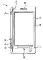
- FIG. 1 is an external view of a mobile communication apparatus 1 to which an information processing apparatus according to a first embodiment of the present invention is applied, viewed from the front.
- the housing 10 of the mobile communication device 1 has a rectangular plate shape.
- an LCD 11 On the front surface of the housing 10, an LCD 11 that displays characters, images, and the like, a touch pad 12, a speaker 13 that outputs sound, an operation area 14, and a microphone 15 that inputs sound are provided.
- the touch pad 12 is made of a substantially transparent material and detects coordinates with which a finger, a stylus pen or the like (hereinafter abbreviated as a finger or the like) is touched, and is installed so as to cover the display screen of the LCD 11. A part thereof protrudes outside the display screen and covers a part of the housing 10.
- a touch pad 12 and the LCD 11 constitute a so-called touch panel.
- the touch pad 12 is a first touch pad installed so as to cover the display screen of the LCD 11 and a second touch pad installed so as to cover a part of the housing 10 adjacent to the display screen of the LCD 11. It may be constituted by. These two touchpads are controlled as a unit.
- the touch pad 12 detects a contact when a finger or the like has been in contact for a predetermined time.
- the detection method of the touch pad 12 may be a pressure-sensitive type that senses a change in pressure on the touch pad 12, or a capacitance that detects a change in capacitance with a finger or the like adjacent to the touch pad 12. It may be an equation or any other method.
- an infrared light emitting element and an illuminance sensor are incorporated in a matrix between the light emitting elements of the LCD 11, and infrared light reflected from the infrared light emitted from the infrared light emitting element by a finger or the like is converted into the above illuminance. You may make it detect with a sensor. According to this method, it is possible to detect a range in which a finger or the like is in contact with the touch pad 12.
- the operation area 14 is a portion where the touch pad 12 protrudes outside the display screen of the LCD 11 and covers the housing 10.
- the touch pad 12 is substantially transparent, the presence of the operation area 14 covered by the touch pad 12 is difficult for the user to visually recognize. Therefore, as shown in FIG. 1, a predetermined figure is written on a part of the housing 10 that is the operation area 14 or on the touch pad 12 that covers the operation area 14, and the user recognizes the position of the operation area 14.
- an operation area 14 for explanation.
- the contact with the touch pad 12 may be referred to as operation, touch, or tap. Further, the contact of the touch pad 12 with the portion covering the display screen of the LCD 11 is simply referred to as the contact with the display screen of the LCD 11. Contact with the touch pad 12 corresponding to the operation area 14 is simply referred to as contact with the operation area 14. It is appropriately selected whether the contact with the operation area 14 is a contact with a portion where the predetermined figure is written, a contact with the outside of the display screen of the LCD 11 and all the portions covered with the touch pad 12. It is a matter to be done.
- a plurality of operation keys 16 to be pressed by the user are provided on the side surface of the housing 10.
- operation keys 16 there are provided a key for inputting limited instructions such as a power on / off key, a call volume adjustment key, and a call origination / end call key for a call.
- a key for inputting limited instructions such as a power on / off key, a call volume adjustment key, and a call origination / end call key for a call.
- a software key for character input is displayed on the LCD 11, and character input is performed by touching the touch pad 12 at a position corresponding to the software key. Many other operations are also performed by touching the touch pad 12.
- FIG. 2 is a block diagram showing a configuration of the mobile communication device 1 according to the embodiment of the present invention.
- the mobile communication device 1 includes a main control unit 20, a power supply circuit unit 21, an input control unit 22 to which operation keys 16 are connected, a touch pad control unit 23 to which a touch pad 12 is connected, an operation pad / pointer control unit 24,
- the display control unit 25 connected to the LCD 11, the storage unit 26, the audio control unit 27 connected to the speaker 13 and the microphone 15, the communication control unit 28 connected to the antenna 28a, and the application unit 29 communicate with each other via a bus. It is connected and configured.
- the application unit 29 has a function of executing a plurality of application software. With this function, the application unit 29 functions as, for example, a tool unit, a file system management unit, a setting unit that sets various parameters of the mobile communication device 1, a music playback unit, and the like.
- the tool unit is a standby processing unit that performs control of waiting for an incoming call, a launcher menu unit that displays a launcher menu for selectively starting a plurality of applications, an e-mail transmitting / receiving unit that transmits and receives e-mails, and a Web browser.
- a tool group such as a browser unit for displaying and an alarm unit for notifying the arrival of a predetermined time is provided. It should be noted that any application may be included in the application of the present invention, so that detailed description of each application is omitted.
- the main control unit 20 includes a CPU (Central Processing Unit) and an OS (Operating System).
- the main control unit 20 performs overall control of each unit of the mobile communication device 1 and performs various other arithmetic processing and control processing.
- the CPU is also used for arithmetic processing by each unit other than the main control unit 20.
- the power supply circuit unit 21 includes a power supply source such as a battery, and switches on / off the power of the mobile communication device 1 in accordance with an operation on the operation key 16 associated with on / off. In some cases, power is supplied from the power supply source to each unit to enable the mobile communication device 1 to operate.
- a power supply source such as a battery
- the input control unit 22 When detecting that the operation key 16 is pressed, the input control unit 22 generates an identification signal for identifying the operated operation key 16 and transmits this signal to the main control unit 20.
- the main control unit 20 controls each unit according to the identification signal.
- the touch pad control unit 23 When the touch pad control unit 23 detects an operation such as a touch on the touch pad 12, the touch pad control unit 23 operates or terminates the operation pad / pointer control unit 24. Further, the touch pad control unit 23 detects the operated position, generates a signal indicating the position, and outputs the signal to the operation pad / pointer control unit 24 or the main control unit 20 as a touch pad operation event.
- the touchpad operation event includes information indicating coordinates indicating a touched position and information indicating each coordinate of a plurality of touched positions in time series.
- the operation pad / pointer control unit 24 causes the LCD 11 to display an operation pad image and a cursor image.
- the touch pad control unit 23 gives the touch pad operation event.
- the operation pad / pointer control unit 24 Based on the touch pad operation event, the operation pad / pointer control unit 24 performs a display for moving the cursor, or detects that a predetermined operation has been performed based on the touch pad operation event. Is sent to the main control unit 20.
- the display control unit 25 generates an image obtained by combining the image requested by the main control unit 20 and the image requested by the operation pad / pointer control unit 24, and displays the combined screen on the LCD 11.
- the storage unit 26 includes a program for executing processing for operating the main control unit 20 and each unit, a nonvolatile memory such as a ROM (Read Only Memory) that stores data necessary for the above processing, the main control unit 20 and each unit.
- RAM Random Access Memory
- Part of the information stored in the storage unit 26 is stored as a file system including a plurality of folders forming a hierarchy and files associated with these folders. This file system is managed by the file system management unit.
- the voice control unit 27 is controlled by the main control unit 20, generates an analog voice signal from the voice collected by the microphone 15, and converts the analog voice signal into a digital voice signal. Further, when a digital audio signal is given, the audio control unit 27 converts the digital audio signal into an analog audio signal based on the control of the main control unit 20, and outputs the sound from the speaker 13.
- the communication control unit 28 is controlled by the main control unit 20, receives a signal transmitted from a base station (not shown) of the mobile communication network via the antenna 28a, and performs spectrum despreading on the signal obtained by the reception. Process and restore data. This data is output to the voice control unit 27 and the application unit 29 in accordance with an instruction from the main control unit 20. When output to the audio control unit 27, the signal processing as described above is performed and output from the speaker 13. When transmitted to the application unit 29, it is output to the display control unit 25, and an image based on the data is displayed on the LCD 11, or the data is recorded in the storage unit 26.
- the communication control unit 28 is controlled by the main control unit 20 and stored in the storage unit 26, voice data collected by the microphone 15, data generated based on operations on the touch pad 12, the operation keys 16, and the like.
- the obtained data is acquired from the application unit 29, spread spectrum processing is performed on the data, converted into a radio signal, and transmitted to the base station via the antenna 28a.
- the operation of the mobile communication device 1 will be described. In the following description, an operation for easily inputting an instruction with one hand regarding the touch pad control unit 23, the operation pad / pointer control unit 24, and the display control unit 25 will be described.
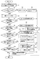
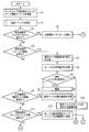
- the touch pad control unit 23 starts the operation illustrated in FIG. 3 at a predetermined time interval or when an interrupt due to the operation of the touch pad 12 occurs.
- the touch pad control unit 23 detects an operation on the touch pad 12, that is, detects a touch pad operation event (step A1).
- the touch pad operation event indicates that the touch pad 12 has been operated, and includes coordinates indicating the operated position. For this reason, for example, when a finger or the like touches the touch pad 12, the touch pad control unit 23 detects the coordinates of the touched position.
- the touchpad control unit 23 detects in time series so that the order of the coordinates of a plurality of touched positions can be understood.
- the touch pad control unit 23 determines whether or not an operation pad is displayed on the LCD 11 (step A2). Whether or not the operation pad is displayed on the LCD 11 corresponds to, for example, whether or not the operation pad / pointer control unit 24 is activated, and therefore is determined by referring to the task management information of the main control unit 20.
- the touch pad control unit 23 determines whether or not the touch pad operation event is generated in the display area of the operation pad (Step S2). A3).
- the position of the display area of the operation pad is controlled by the operation pad / pointer control unit 24, notified to the main control unit 20, and stored in the main control unit 20 as part of the resource management information. Therefore, it is obtained by referring to the resource management information.
- the touch pad control unit 23 transmits the touch pad operation event to the operation pad / pointer control unit 24 (Step A4), and performs the operation. finish.
- the touch pad control unit 23 transmits the touch pad operation event to the main control unit 20 (step A7) and ends the operation.
- the touch pad operation event is an action event for displaying the operation pad (step A5).
- step A5 the touch pad control unit 23 activates the operation pad / pointer control unit 24 to display the operation pad (step A6), and ends the operation.
- the touch pad operation event is transmitted to the main control unit 20 (step A7), and the operation is terminated.
- FIG. 4 shows a display state of the LCD 11 on which no operation pad is displayed.
- the launcher menu section is operating.
- the display of the LCD 11 shown in this figure is an image created by the main control unit 20.
- the first specific function display 11 a is displayed on the upper left of the display screen, and the second specific function display 11 b is displayed on the upper right of the display screen.
- Six icons corresponding to the launcher menu portion are displayed in the remaining area.
- the touch pad operation event is generated with respect to any of the first specific function display 11a, the second specific function display 11b, or the six icons in a state where the operation pad is not displayed in this manner
- the touch pad operation event is As described in the operation of step A7, the data is transmitted to the main control unit 20.
- the main control unit 20 performs common control independent of the operating application. .
- This common control is, for example, control for ending an operating application, control for starting a specific application, and control for displaying a function menu of the main control unit 20.
- the main control unit 20 transmits a touchpad operation event to the operating application, that is, the launcher menu unit.
- the launcher menu unit performs control for starting an application corresponding to the operated icon in accordance with a given touchpad operation event.
- the action event for displaying the operation pad is generated by an operation in which the finger 40 contacts the operation area 14 and the finger 40 moves on the LCD 11 while the contact is maintained. In other words, it is generated by the user moving the touched position on the LCD 11 while the finger 40 is in contact with the operation area 14 and the finger 40 is in contact with the touch pad 12.
- the mobile communication device 1 is held by the right hand, and the finger 40 is the thumb of the right hand.
- step A6 the process for displaying the operation pad is performed as described in step A6.
- the details are shown in the flowchart of FIG.
- the operation pad / pointer control unit 24 starts the processing shown in FIG. 5, and receives a request to display the operation pad from the touch pad control unit 23 (step B1). Then, processing related to the operation pad is started (step B2).
- the operation pad / pointer control unit 24 creates image data including the operation pad and the cursor (step B3), and outputs the image data to the display control unit 25 to request display (step B4).
- an icon flag indicating whether or not the operation pad is iconified is reset (step B5), and the process ends. The icon flag indicates that the operation pad is not iconified by the reset, and that the icon is iconified by the set.
- the operation pad / pointer control unit 24 receives the touch pad operation event from the touch pad control unit 23, and this touch pad operation event. Control according to. For example, the operation pad is iconified / de-iconified, or the display position of the cursor is moved, the display position of the operation pad is moved, the display of the operation pad is terminated, or the touch pad 12 is operated. Or notify the control unit 20.
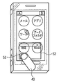
- the cursor 51 and the operation pad 52 will be described with reference to FIG. These are all images displayed on the LCD 11, and the cursor 51 is a pointer that identifies the position of the display screen of the LCD 11, and is a figure of an arrow. The figure is not limited to an arrow.
- the operation pad 52 is an image including a tap event transmission button 53, an operation pad moving area 54, an iconization button 55, and a cursor operation area 56 which is a part other than these.
- a tap event transmission operation event is generated by the touch pad control unit 23 and output to the main control unit 20.
- This tap event transmission operation event indicates that the position indicated by the cursor 51 has been selected regardless of the operation pad 52. That is, the tap event transmission button 53 is a button for generating an event having the same effect as tapping the position indicated by the cursor 51.
- the main control unit 20 may newly start an application, for example, and the main control unit 20 may change an image to be displayed.
- the displayed operation pad 52 is not changed at all, and input via the operation pad 52 can be continued.
- the operation pad 52 is a general-purpose input means that does not depend on an application or the like. This is because, for example, it is more appropriate to continue using a newly started application.
- the touch pad control unit 23 When the finger 40 moves while touching the operation pad moving area 54, the touch pad control unit 23 that has detected the finger 40 generates an operation pad moving operation event. That is, the operation pad moving area 54 is an area used for moving the position where the operation pad 52 is displayed following the movement of the finger 40.
- the touch pad control unit 23 When the finger 40 moves to the operation area 14 outside the display screen of the LCD 11 while being in contact with the operation pad moving area 54, the touch pad control unit 23 generates an operation pad end operation event, and the operation pad 52 The display is cleared.
- the operation pad end operation event can be generated by an operation in which the user touches the operation pad moving area 54 with the finger 40 and slides the finger 40 on the touch pad 12 outside the LCD 11 while keeping the contact. At this time, at least a part of the operation pad 52 goes out of the display screen of the LCD 11, and the part is not displayed on the LCD 11.
- the icon button 55 is a button for generating an operation pad icon operation event by the touch pad control unit 23 when the finger 40 comes into contact with the button, and converting the operation pad 52 into an icon.
- the cursor operation area 56 when the finger 40 comes into contact with this area, a cursor movement operation event is generated by the touch pad control unit 23, and the display position of the cursor 51 is changed in response to the movement of the finger 40 in contact with the operation pad 52. It is an area for moving up, down, left and right.
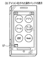
- FIG. 7 shows the LCD 11 that displays the iconized operation pad 57.
- the operation pad / pointer control unit 24 does not display the cursor 51.
- the touch pad control unit 23 When the finger 40 comes into contact with the operation pad 57, the touch pad control unit 23 generates an operation event. Then, when this operation event is generated, the iconized operation pad 57 is made non-icon, and instead, the cursor 51 and the operation pad 52 are displayed.
- the operation pad / pointer control unit 24 when the operation pad 52 is displayed will be described with reference to the flowchart shown in FIG.
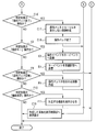
- the operation pad / pointer control unit 24 starts the processing illustrated in FIG. First, the operation pad / pointer control unit 24 receives a touch pad operation event from the touch pad control unit 23 (step C1), and determines whether an icon flag is set (step C2).
- step C2 If the icon flag is set (YES in step C2), the operation pad / pointer control unit 24 transitions to a non-iconification state (step C3) and resets the icon flag (step C4). Further, the operation pad / pointer control unit 24 creates image data for displaying the operation pad 52 and the cursor 51 in place of the operation pad 57 which is an icon of the operation pad 52 (step C10), and performs display control of this image data. By giving to the unit 25, a request to display the image of the operation pad 52 and the cursor 51 is made (step C19), and the process is terminated.
- the operation pad / pointer control unit 24 determines the touch pad operation event received from the touch pad control unit 23 (step C5).
- the touch pad operation event is an operation of moving the cursor, an operation of moving the operation pad, an operation of transmitting a tap event, an operation of iconifying the operation pad, an operation of ending the display of the operation pad, or It is determined which of the other is indicated.
- the specific content of the touch operation that is the determination criterion for the operation is as described above with reference to FIG.
- Step C6 When the determination result is an operation of moving the cursor (YES in Step C6), the operation pad / pointer control unit 24 displays the display coordinates of the cursor 51 after the movement based on the coordinate information included in the touchpad operation event. (Step C7), and in step C10, image data including the operation pad 52 and the cursor 51 is created so that the cursor 51 is displayed at a position according to the calculation result.
- the operation of moving the cursor 51 is performed by moving the finger 40 on the cursor operation area 56. For this reason, when the finger 40 is touching the cursor operation area 56, the processing of Step C7 and Step C10 is continued.
- the operation pad / pointer control unit 24 moves the operation pad 52 after the movement based on the coordinate information included in the touch pad operation event. Is displayed (step C9), and image data including the operation pad 52 and the cursor 51 is created in step C10 so that the operation pad 52 is displayed at a position according to the calculation result.
- the operation of moving the operation pad 52 is performed by moving the finger 40 touching the operation pad moving area 54 while touching it. For this reason, when the finger 40 is touching the operation pad moving area 54, the processes of Step C9 and Step C10 are continuously performed.
- the operation pad / pointer control unit 24 transmits a tap event including information on the coordinates of the display position of the cursor 51 to the main control unit 20. (Step C12).
- the determination result is an operation for iconifying the operation pad (YES in step C13)
- the operation pad / pointer control unit 24 sets an icon flag indicating that the operation pad is iconized (step C14), and the operation pad Image data for displaying the iconized operation pad 57 instead of 52 is created (step C15). Then, the operation pad / pointer control unit 24 gives the image data to the display control unit 25, thereby making a request to display the operation pad 57 (step C19), and ends the processing.
- the operation pad / pointer control unit 24 creates image data that does not display the operation pad 52 and the cursor 51 (Step C17). ), The input process via the operation pad is terminated (step C18). Then, the operation pad / pointer control unit 24 gives the image data to the display control unit 25, thereby making a request to display an image that does not display the operation pad 52 and the cursor 51 (step C19). And the cursor 51 are deleted, and the processing is terminated. If the determination result is other than that (determined as NO in step C16), it is determined that the event is an unnecessary event, and the process ends without performing the process.
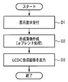
- the display control unit 25 transmits a display request from the main control unit 20 or the operation pad / pointer control unit 24, the display control unit 25 starts the process illustrated in FIG.
- the display control unit 25 receives the request (step D1), and synthesizes the image requested to be displayed from the main control unit 20 and the image requested to be displayed from the operation pad / pointer control unit 24.
- the created image is created (step D2), and the created composite image is displayed on the LCD 11 (step D3). For example, the image is synthesized by ⁇ blending.
- the composite image 58 shown in FIG. 10 is an image obtained by combining the image shown in FIG. 4 created by the main control unit 20 and the image shown in FIG. 6 created by the operation pad / pointer control unit 24 by an ⁇ blend process. is there. As shown in this image, an image created by the main control unit 20 is visible, and a user interface using the operation pad 52 is provided.
- FIG. 11 is a diagram illustrating an example of an operation for moving the cursor.
- the operation pad / The pointer control unit 24 and the display control unit 25 perform display in which the cursor 51 moves.
- FIG. 11 by sliding the finger 40 to the left, a display is made in which the cursor moves to the left from the position shown in FIG.
- the cursor 51 moves in the same direction as the direction in which the finger 40 is slid on the cursor operation area 56.
- the operation pad / pointer control unit 24 determines that an operation for moving the cursor has occurred by the determination processing in step C5 of FIG. judge.
- FIG. 12 is a diagram for explaining an example of an operation for moving the operation pad 52.
- a display for moving the operation pad 52 by the operation pad / pointer control unit 24 and the display control unit 25 is displayed.
- the operation pad 52 is displayed to move downward from the position shown in FIG.
- the operation pad 52 moves according to the operation of the finger 40.
- the operation pad / pointer control unit 24 performs an operation of moving the operation pad 52 by the determination process in step C5 of FIG. It is determined that
- FIG. 13 is a diagram illustrating an example of an operation for sending a tap event.
- the tap event transmission button 53 is touched (tapped) with the finger 40, a touch pad operation event generated by the touch pad control unit 23 in response to this operation is given to the operation pad / pointer control unit 24.
- the operation pad / pointer control unit 24 determines that a tap event transmission operation has occurred by the determination processing in step 5C of FIG. As a result, the operation pad / pointer control unit 24 transmits an event indicating that the position indicated by the cursor 51 has been tapped to the main control unit 20 regardless of the operation pad 52.
- the main control unit 20 activates a tool unit corresponding to the icon among the tool units included in the application unit 29.
- FIG. 14A and FIG. 14B are diagrams for explaining an example of an operation for converting the operation pad 52 into an icon.
- FIG. 14A shows an operation of tapping the iconized button 55 of the operation pad 52 with the finger 40.
- the operation pad 52 is iconified by tapping the iconize button 55 with the finger 40.
- the operation pad / pointer control unit 24 performs an operation to convert the operation pad 52 into an icon by the determination process in step C5 of FIG. It is determined that it has occurred.
- FIG. 14B shows a state in which an iconized operation pad 57 is displayed in place of the operation pad 52.
- the operation pad 57 may be touched (tapped) with the finger 40.
- FIG. 15 is a diagram for explaining an example of an operation for ending the display of the operation pad 52.
- the finger 40 After touching the operation pad moving area 54 on the operation pad 52 with the finger 40, the finger 40 is slid down on the touch pad 12 as it is and the finger 40 is moved to the operation area 14. Can be terminated.
- the operation pad / pointer control unit 24 performs an operation to end the display of the operation pad 52 by the determination process in step C5 of FIG. Is determined to have occurred.
- the touch pad control unit 23 detects this action from the detection result of the touch pad 12, and notifies the operation pad / pointer control unit 24 as a touch pad operation event.
- the operation pad / pointer control unit 24 determines in step C16 that the action is to end the display of the operation pad, and controls the display control unit 25 to end the display of the operation pad 52.
- the operation pad 52 may be displayed by the opposite operation. That is, the user performs an action of sliding on the LCD 11 while touching the operation area 14 with the finger 40. Then, the touch pad control unit 23 detects this action from the detection result of the touch pad 12, and notifies the operation pad / pointer control unit 24 as a touch pad operation event. On the other hand, the operation pad / pointer control unit 24 determines that the action is to start displaying the operation pad, and controls the display control unit 25 to display the operation pad 52.
- the mobile communication apparatus 1 to which the information processing apparatus according to the second embodiment is applied has an apparently similar configuration to the mobile communication apparatus 1 described in the first embodiment shown in FIGS. Therefore, the configuration of the mobile communication device 1 to which the information processing device according to the second embodiment is applied will be described by assigning the same reference numerals to the same parts as those of the mobile communication device 1 according to the first embodiment. . In the following description, differences will be mainly described, and points that are not particularly described are the same as those of the mobile communication device 1 according to the first embodiment.
- the mobile communication device 1 to which the information processing device according to the second embodiment is applied has an operation pad and an operation for processing a user operation via the operation pad.
- the operation of the pad / pointer control unit 24 is partially different.
- the operation pad 70 is an image provided with a tap event sending button 53, an operation pad moving area 54, and an icon button 55.
- a cross key button (up key button 71a, down key button 71b, right key) is displayed.
- the image includes a button 71c, a left key button 71d), an enter key button 72, and a cursor operation area 56 that is a part other than these.
- the cross key button is illustrated as having an arrow graphic displayed thereon, but may be a graphic other than an arrow graphic.
- the cross key button and the determination key button 72 are used, for example, to select one of the items displayed on the LCD 11 by the application and cause the application to perform an operation corresponding to the selected item. That is, the application displays an item and selects one item from the displayed items.
- the selected item is highlighted and displayed so that it can be distinguished from other items. In the following description, this highlighted display is referred to as a focus display.
- the application selects an item displayed above the selected item, and when the down key button 71b is operated, the application is displayed below the selected item. Select an item.
- the application selects an item displayed on the right side of the selected item, and when the left key button 71d is operated, the application is displayed on the left side of the selected item. Select an item.
- the enter key button 72 is operated, the application performs an operation corresponding to the selected item (the focused item).
- any of the input using the cross key button and the determination key button 72 and the input using the cursor 51 and the tap event transmission button 53 described in the first embodiment can be performed in various ways. You can control the application.
- the six icons displayed by the launcher menu section are arranged in an orderly manner in the top, bottom, left, and right, so that input using the cross key button and the enter key button 72 is suitable.
- anchors included in the Web content displayed by the browser unit are often not arranged in an orderly manner, and therefore input using the cursor 51 or the tap event transmission button 53 is suitable.
- the mobile communication device 1 includes two input methods, the user can always use a desired method.
- the operation pad / pointer control unit 24 executes Step E1 instead of Step C5 in FIG.
- the operation pad / pointer control unit 24 determines the touch pad operation event received from the touch pad control unit 23.
- the operation pad / pointer control unit 24 is configured such that the touch pad operation event is an operation of moving a cursor, an operation of moving the operation pad, an operation of transmitting a tap event, an operation of iconifying the operation pad, an operation pad It is determined which one of the operation to end the display and the operation on the operation key is indicated.
- the operation with respect to the operation key means an operation with respect to the cross key button or an operation with respect to the determination key button 72, and based on the coordinates indicating the operated position included in the touchpad operation event, Determine if the operation has been performed.
- step E2 when it is determined in step C16 that the touch pad operation event is not an operation for ending display of the operation pad, the operation pad / pointer control unit 24 executes step E2.
- step E2 the operation pad / pointer control unit 24 determines whether the determination result is an operation on the operation key.
- the operation pad / pointer control unit 24 operates the operation key corresponding to the coordinates included in the touchpad operation event.
- a key event indicating this is generated (step E3), this key event is transmitted to the main control unit 20 (step E4), and the operation is terminated.
- the main control unit 20 controls the display control unit 25 to move the display position of the focus display 74 according to the operation on the operation key.
- the main control unit 20 moves the focus display to one of the up, down, left, and right items according to the coincident button.
- the display control unit 25 combines the image requested to be displayed from the main control unit 20 and the image requested to be displayed from the operation pad / pointer control unit 24.
- the control for displaying the synthesized image on the LCD 11 will be described.
- a composite image 73 shown in FIG. 19 includes an operation pad 70 instead of the operation pad 52 as compared with the composite image 58 shown in FIG.
- the synthesized image 73 is synthesized with a focus display 74 by the main control unit 20.
- the focus display 74 is a pointer that highlights and displays an item selected by the operation of the cross key button among items displayed by the application so that it can be distinguished from other items.
- the focus display 74 is a rectangular thick frame and surrounds the selected item. Note that the first specific function display 11a and the second specific function display 11b are not displayed by the application, and thus are not targeted for the focus display 74 to be emphasized.
- the focus display 74 is not limited to a rectangle, and an arbitrary color may be set or blinked.
- the main control unit 20 has been described as creating the focus display 74 and controlling the display position.
- the present invention is not limited to this.
- the operation pad / pointer control unit 24 may play the role.
- the mobile communication device 1 to which the information processing apparatus according to the third embodiment is applied includes the mobile communication device 1 of the first embodiment and the mobile communication device 1 of the second embodiment shown in FIGS. It is similar. Therefore, the same parts as those of the mobile communication device 1 according to the first and second embodiments are denoted by the same reference numerals, and redundant description will be omitted, and differences will be described.
- the mobile communication device 1 to which the information processing device according to the third embodiment is applied has an operation pad and a user operation via the operation pad.
- the operation pad / pointer control unit 24 to be processed is partially different.
- first to third kinds of operation pads are provided, and one operation pad is selectively displayed.
- the operation pad that is newly displayed when a predetermined operation is performed after the operation pad is changed from the displayed state to the non-display state is the same as the operation pad that is displayed immediately before the operation pad is hidden. It is a kind of operation pad.
- the control for displaying each operation pad is simple and clear. For this reason, the user is less likely to perform an erroneous operation.
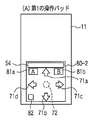
- the first operation pad 80 includes an operation pad moving area 54 and cross key buttons (up key button 71a, down key button 71b, right key button 71c, and left key button 71d. ), An enter key button 72, a first specific function display 81a, a second specific function display 81b, and an operation pad switching button 82.
- the first specific function display 81a and the second specific function display 81b correspond to the first specific function display 11a and the second specific function display 11b shown in FIG. 4, respectively.
- the first specific function display 11 a and the second specific function display 11 b are displayed at the upper corner of the LCD 11 and are out of the scope of the focus display 74. For this reason, when the mobile communication device 1 is used with one hand, it is difficult to touch the first specific function display 11a or the second specific function display 11b with the finger 40. It is necessary to change the communication device 1. In contrast, since the first specific function display 81a and the second specific function display 81b are displayed in the first operation pad 80, even when the mobile communication device 1 is used with one hand, It can be easily touched with the finger 40.
- the operation pad switching button 82 is a software key for displaying a second operation pad instead of the first operation pad 80 under the control of the main control unit 20 when a long press operation is performed.
- long press operation is operation which contacts continuously for predetermined time or more.
- the focus display 74 is displayed under the control of the main control unit 20 and the display position thereof is controlled as in the operation pad 70 of the second embodiment.
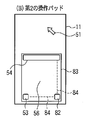
- the second operation pad 83 includes a tap event transmission button 53, an operation pad moving area 54, an operation pad switching button 82, a scroll bar 84, and a cursor operation area that is a part other than these. 56.
- the operation pad switching button 82 is a software key for displaying a third operation pad instead of the second operation pad 83 under the control of the main control unit 20 when a long press operation is performed.
- the main control unit 20 controls to display the cursor 51 as well.
- the scroll bar 84 includes a vertical bar along the right side of the second operation pad 83 and a horizontal bar along the lower side of the second operation pad 83, and is displayed when the finger 40 is moved on the vertical bar.
- the main control unit 20 scrolls the displayed image in the vertical direction, and when the finger 40 is moved on the horizontal bar, the displayed image is scrolled and displayed by the main control unit 20 in the horizontal direction.
- the operation pad switching button 82 requires a long press operation regardless of the type of the displayed operation pad. The reason is mainly in the second operation pad 83. In the second operation pad 83, the finger 40 moves widely on the cursor operation area 56, so that the operation pad is not switched when the finger 40 accidentally touches the operation pad switching button 82.
- the switch button 82 is operated by a long press operation. In addition, if the operation on the operation pad switching button 82 is different for each operation pad, the user is confused, so the operation is unified to a long press operation.
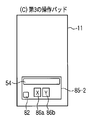
- the third operation pad 85 is an image including an operation pad moving area 54, an operation pad switching button 82, a first function display 86a, and a second function display 86b. .
- the operation pad switching button 82 is a software key for displaying the first operation pad 80 instead of the third operation pad 85 under the control of the main control unit 20 when a long press operation is performed.
- the sizes of the first to third operation pads 80, 83, 85 may be different from each other. Since the second operation pad 83 has the cursor operation area 56, it is preferable that the second operation pad 83 be large. However, since the image created by the main control unit 20 and the operation pad are combined and displayed on the LCD 11, it is inevitable that the operation pad causes some difficulty in viewing. For this reason, any operation pad may be of a size that can be touched by the movement of the finger 40, and it is preferable not to exceed this size.
- the third operation pad 85 since the third operation pad 85 has a small amount of content to be displayed, it can be displayed in a small size. However, in any of the first to third operation pads 80, 83, 85, the operation pad switching button 82 is displayed at a common position on the display screen of the LCD 11. Thereby, the first to third operation pads 80, 83, 85 can be switched easily and continuously.
- the operation pad according to the third embodiment is not converted into an icon. Therefore, the operation pad / pointer control unit 24 performs the operations of Step C2 to Step C4 and Step C13 to Step C15 of FIG. 8 which are operations for iconifying and displaying the icons. Do not do.
- the operation pad / pointer control unit 24 executes Step F1 instead of Step C5.
- the operation pad / pointer control unit 24 determines the touch pad operation event received from the touch pad control unit 23. Specifically, the operation pad / pointer control unit 24 displays a touch pad operation event for an operation on a scroll bar, an operation for moving a cursor, an operation for moving an operation pad, an operation for transmitting a tap event, and an operation pad display. It is determined which one of the operation to end, the operation with respect to the operation key, the operation to switch the operation pad, and the operation to execute the displayed function is indicated. It is not determined whether the operation pad is an icon operation.
- the operation with respect to the scroll bar is an operation with respect to the scroll bar 84.
- the operation of switching the operation pad is an operation on the operation pad switching button 82.
- the operation for executing the displayed function is an operation for the first and second specific function displays 81a and 81b and the first and second function displays 86a and 86b.
- step F2 If the determination result is an operation on the scroll bar (YES in step F2; this determination is made only when the second operation pad 83 is displayed), the operation pad / pointer control unit 24
- the main control unit 20 is instructed to scroll and display the image displayed on the LCD 11 in the horizontal direction or the vertical direction (step F3), and the operation ends.
- the main control unit 20 controls the display control unit 25 to scroll the image displayed on the LCD 11 in the horizontal direction when the horizontal bar is operated, while the vertical bar is operated. In such a case, the image displayed on the LCD 11 is scroll-displayed in the vertical direction.
- Step C6 When the determination result is an operation of moving the cursor (determined as YES in Step C6, this determination is performed only when the second operation pad 83 is displayed), the operation pad / pointer control unit 24 Instead of step C7, steps F4 to F7 are performed.
- the operation pad / pointer control unit 24 instructs the main control unit 20 to change the display form of the operation pad moving area 54 (step F4).
- the main control unit 20 controls the display control unit 25 to change the display form.
- the change in the display form is to indicate to the user that the operation via the cursor operation area 56 has been performed. For example, the color, darkness, design, or the like is changed, or the display is blinked.
- the operation pad / pointer control unit 24 calculates the display coordinates of the cursor 51 as in Step C7 (Step F5).
- the operation pad / pointer control unit 24 determines whether or not the position where the finger 40 is in contact is outside the second operation pad 83 based on the coordinate information included in the touch pad operation event. Determine (step F6). When it is determined that it is outside, in other words, when the finger 40 moves out of the second operation pad 83 while being in contact, the operation pad / pointer control unit 24 notifies the main control unit 20 of this fact. (Step F7). As a result, the main control unit 20 vibrates a vibrator (not shown) and notifies the user that the position is outside the second operation pad 83 and the operation is invalid. On the other hand, if it is determined that it is not outside, the process proceeds to step C10 without performing the above notification, and an image in which the operation pad and the moved cursor 51 are combined is displayed.
- step F7 instead of the above notification, the operation pad / pointer control unit 24 may move and display the second operation pad 83 following the position where the finger 40 is in contact. good. That is, in this case, unlike the above, an operation accompanying the movement of the finger 40 to the outside of the second operation pad 83 is accepted. Further, the positions at which the first operation pad 80 and the third operation pad 85 are displayed may be moved in accordance with the movement of the position at which the second operation pad 83 is displayed. Even if the display positions of the first to third operation pads are changed, the display position of the operation pad switching button 82 may be controlled to be displayed at the same position without being changed. These controls are performed by the main control unit 20 and the display control unit 25 when the operation pad / pointer control unit 24 gives an instruction to the main control unit 20.
- step E2 If the determination result is not an operation with respect to the operation key (NO in step E2), the operation pad / pointer control unit 24 proceeds to step F8. If the determination result is an operation for switching the operation pad (YES in Step F8), the operation pad / pointer control unit 24 replaces the currently displayed operation pad with the next type of operation pad. An image to be displayed is created and output to the display control unit 25 (step F9), and the process proceeds to step C19. The cursor 51 is displayed only when the second operation pad 83 is displayed.
- the determination result is an operation for executing the displayed function (determined as YES in step F10.
- This determination is made when the first operation pad 80 or the third operation pad 85 is displayed.
- the operation pad / pointer control unit 24 notifies the main control unit 20 of the operated function, and the main control unit 20 thereby executes a function corresponding to the notified function ( Step F11), the process ends.
- the operated displays are the first and second specific function displays 81a and 81b
- events in which the first and second specific function displays 81a and 81b are operated to the main control unit 20, respectively. Send the message that occurred.
- the first and second function displays 86a and 86b are operated, the main control unit 20 is instructed to start predetermined applications.
- the display control unit 25 generates the composite image by combining the image requested to be displayed by the main control unit 20 and the image requested to be displayed by the operation pad / pointer control unit 24.
- FIG. 23 illustrates a composite image 91 including the first operation pad 80 and the focus display 74.
- the focus display 74 is created by the main control unit 20.
- a composite image 92 including the second operation pad 83 and the cursor 51 is illustrated in FIG.
- a composite image 93 including the third operation pad 85 is illustrated in FIG.
- the third operation pad 85 is a pad for quickly activating a function associated with the first specific function display 81a or the second specific function display 81b, and the cursor 51 and the focus display 74 are not displayed.
- FIGS. 26A, 26B, and 26C a first operation pad that is a modification of the first to third operation pads 80, 83, and 85 shown in FIGS. 20A, 20B, and 20C.
- the 80-2, the second operation pad 83-2, and the third operation pad 85-2 will be described.
- the first operation pad 80-2, the second operation pad 83-2, and the third operation pad 85-2 are compared with the first to third operation pads 80, 83, and 85, respectively.
- the position of the switching button 82 is different.
- the operation pad switching button 82 is displayed on the lower right portion of the operation pad, but the first to third operation pads 80-2 and 83 are displayed. -2 and 85-2 are displayed at the lower left. Further, in the second operation pad 83-2, the display position of the scroll bar 84 is changed in accordance with the change in the position of the operation pad switching button 82, and the tap event is transmitted as compared with the second operation pad 83. The position of the button 53 is also changed. The positions of buttons and areas used for other operations are not changed.
- first to third operation pads 80, 83, 85 or the first to third operation pads 80-2, 83-2, 85-2 is used depends on the user's dominant hand and preference. Select accordingly. Regardless of which group is selected, when the operation pad display is ended and the operation pad is displayed again, the operation pads of the same group are displayed. Further, when the first to third operation pads 80-2, 83-2, and 85-2 are used, the operation pad switching button 82 is displayed at a common position on the display screen of the LCD 11 in any of the operation pads.
- the main control unit 20 controls as described above.
- the first to third operation pads 80, 83, and 85 have been described as being selectively used.
- the present invention is not limited to this, and any two types are possible. Also good.
- the operation pad / pointer control unit 24 operates in the test mode.
- the test mode is an operation mode for checking whether or not the user can easily move the finger 40 in contact with the intended button or region or move it while in contact.
- the test mode is started by the operation pad / pointer control unit 24, for example, at the initial setting when the user uses the mobile communication device 1 for the first time or when the user performs a predetermined operation on the operation key 16.
- the operation pad / pointer control unit 24 determines that the user cannot easily operate, the operation pad is enlarged, the buttons are enlarged, and the interval between the buttons is increased so that the operation is easy. Increase the input area.
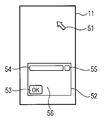
- the operation pad / pointer control unit 24 causes the LCD 11 to display one of the operation pads described above or the operation pad 95 dedicated to the test mode illustrated in FIG. Then, the operation pad / pointer control unit 24 displays a message display 96 on the LCD 11 or outputs a voice message from a speaker for music generation (not shown) and outputs it to the operation pad 95 to the user. The user is prompted to operate any one of the included test buttons 97. Thereafter, the operation pad / pointer control unit 24 detects the time until the operation and the touched position, and determines whether or not the user can easily operate based on the detection result. As shown in FIG. 27, since the test buttons 97 are prepared in a dense arrangement and a sparse arrangement, it is determined whether the user can easily operate by testing both of them. can do.
- the second specific operation table 83a or the second specific function display 81b may be included in the second operation pad 83 or the third operation pad 85 of the third embodiment.
- the finger 40 moves out of the second operation pad 83 while being in contact, a notification to that effect is given, or the position where the second operation pad 83 is displayed is moved.
- this processing can be applied to operation pads other than the second operation pad 83.
- the portable type does not necessarily mean that it is not connected to another device via a cable.
- the present invention is applied to a small operation input device connected to an arbitrary device via a flexible signal transmission / reception cable, or a small device supplied with power via a flexible commercial power cable. Is possible.
- the present invention is not limited to the above configuration, and various modifications are possible.
- 1 mobile communication device, 10: housing, 11: LCD, 11a, 81a: first specific function display, 11b, 81b: second specific function display, 12: touch pad, 14: operation area, 16: operation 20: main control unit, 22: input control unit, 23: touch pad control unit, 24: operation pad / pointer control unit, 25: display control unit, 29: application unit, 40: finger, 51: cursor, 52 , 70, 95: Operation pad, 53: Tap event transmission button, 54: Operation pad movement area, 55: Iconization button, 56: Cursor operation area, 57: Iconized operation pad, 58, 73, 91, 92 93: Composite image, 71a: Up key button, 71b: Down key button, 71c: Right key button, 71d: Left key button, 72: Enter key button, 74: Focus Display, 80, 80-2: First operation pad, 82: Operation pad switching button, 83, 83-2: Second operation pad, 84: Scroll bar, 85, 85-2: Third operation pad,
Abstract
タッチパッドが設置されたLCD(11)に、第1~第3の操作パッド(80、83、85)のいずれか1つを表示し、それらの操作パッド内のソフトウェアキーに指で触れたり、あるいは、触れたまま指等を移動させると、装置は入力を受け付け、入力に応じた動作を行う。操作パッドを切り替えるための操作パッド切替ボタン(82)は、第1~第3の操作パッド(80、83、85)に共通して同じ位置に表示されるようにしたものである。
Description
本発明は、情報処理装置に係り、特に、接触による入力処理に関する。
入力のための領域をタッチパネルに表示し、その領域に対して、指やスタイラスペン等が接触されること、また、接触されたまま移動が行われることに応じて、所定の動作をし、そして、タッチパネルに表示されるカーソルの位置を移動する情報処理装置が知られている(例えば、特許文献1参照。)。
ここで、タッチパネルは、ディスプレイと、その前面に貼られた感圧式又は静電容量式のタッチパッドとからなる。ディスプレイは、LCD(Liquid Crystal Display)、有機ELディスプレイ(Organic Electroluminescence Display)等、任意の表示装置である。タッチパッドは、指やスタイラスペンの接触の検出をしたり、指やスタイラスペンが所定の距離以内に近づいたことを検出する。
タッチパネルを介した入力は、携帯型の装置、例えば、移動通信装置、スマートフォン(Smartphone)、ゲーム装置等で用いられている。このようなタッチパネル付きの携帯型の装置は、片手で保持される。そして、使用者は、もう一方の手でスタイラスペンを持ち、タッチパネルに対してスタイラスペンや指(例えば人差し指)を用いて操作を行う。このように、タッチパネル付きの携帯型の装置は、両手を用いて入力操作することが想定されている。
しかしながら、上述した特許文献1に開示されている方法では、携帯型の装置におけるタッチパネルを介した入力の使い易さが考慮されていないという問題があった。この問題は、例えば列車内等で片手でつり革に掴まり、片手しか使用することができない状況下で、顕著となる。
即ち、携帯型の装置は、片方の手のひらで保持し、その手の指(例えば、親指)で容易に操作できることが望まれる。しかし、従来の装置では、暗黙のうちに両手を用いることが想定されていた。第1の理由としては、入力領域の大きさが考慮されていないことである。この入力領域が広い場合、片手での使用は不可能である。
第2の理由としては、アイコンや操作キー等のソフトウェアキーがタッチパネル上に小さく表示されることである。タッチパネルを備えた携帯型の装置では、これらのソフトウェアキーをタッチする等の操作によって入力が行なわれるが、これらのソフトウェアキーが小さい。このため、スタイラスペンの使用が必要である。片方の手だけで、装置を保持し、スタイラスペンを用いて入力することは不可能である。
本発明は上記問題を解決するためになされたもので、片手だけで容易に入力することができる情報処理装置を提供することを目的とする。
上記目的を達成するために、本発明の情報処理装置は、表示を行うとともに、その表示に対する操作を検出するタッチパネルと、前記タッチパネルに、第1切替ボタンを有する第1の操作パッドと第2切替ボタンを有する第2の操作パッドのうち、いずれか一方を選択的に表示させる前記タッチパネルが前記第1切替ボタンに対する操作を検出した場合に、前記第1の操作パッドに代えて前記第2の操作パッドを表示させ、一方、前記タッチパネルが前記第2切替ボタンに対する操作を検出した場合に、前記第2の操作パッドに代えて前記第1の操作パッドを表示させる表示制御手段とを具備したことを特徴とする。
本発明によれば、片手で容易に操作可能な情報処理装置を提供する。
以下に、本発明の実施形態に係わる情報処理装置の実施の形態を、図面を参照して説明する。
(第1の実施形態)
図1は、本発明の第1の実施形態に係わる情報処理装置が適用された移動通信装置1を略正面から見た外観図である。この移動通信装置1の筐体10は、矩形の板状である。
図1は、本発明の第1の実施形態に係わる情報処理装置が適用された移動通信装置1を略正面から見た外観図である。この移動通信装置1の筐体10は、矩形の板状である。
筐体10の正面には、文字や画像等を表示するLCD11と、タッチパッド12と、音声を出力するスピーカー13と、操作領域14と、音声を入力するマイク15が設けられている。タッチパッド12は、略透明の素材からなり、指やスタイラスペン等(以下、指などと略称する)が接触された座標を検出するもので、LCD11の表示画面を覆うように設置され、更に、その一部は上記表示画面外にはみ出し、筐体10の一部を覆っている。このようなタッチパッド12とLCD11によって、いわゆるタッチパネルを構成している。なお、タッチパッド12は、LCD11の表示画面を覆うように設置された第1のタッチパッドと、LCD11の表示画面に隣接する筐体10の一部を覆うように設置された第2のタッチパッドとにより構成されても良い。これらの2つのタッチパッドは、一体として制御される。
タッチパッド12は、所定の時間に渡って指等が接触している場合に、接触として検出する。タッチパッド12の検出方法は、タッチパッド12に対する圧力の変化を感知する感圧式であってもよいし、タッチパッド12に近接する指等との間の静電容量の変化を検出する静電容量式であってもよく、その他の方法であっても良い。例えば、LCD11の発光素子の間に赤外光発光素子と、照度センサーとをマトリックス状に組み込み、赤外光発光素子から発せされた赤外光が指等によって反射された赤外光を上記照度センサーによって検出するようにしてもよい。この方法によれば、指等がタッチパッド12に接触した範囲を検出することができる。
操作領域14は、タッチパッド12がLCD11の表示画面外にはみ出して、筐体10を覆う部分である。しかし、タッチパッド12は略透明であるため、これにより覆われた操作領域14の存在は使用者に視認され難い。そこで、図1に示すように、操作領域14である筐体10の一部に、又は、操作領域14を覆うタッチパッド12上に所定の図形を記し、使用者に操作領域14の位置を認識させる。以後、上記図形が記された部分を操作領域14と称して説明する。
また、以後の説明で、タッチパッド12への接触を、操作、タッチ、また、タップと称することがある。また、タッチパッド12のLCD11の表示画面を覆う部分への接触を、単にLCD11の表示画面への接触と称する。操作領域14に対応するタッチパッド12への接触を、単に操作領域14への接触と称する。操作領域14への接触は、上記所定の図形が記された部分への接触、LCD11の表示画面外で、かつ、タッチパッド12に覆われた全ての部分への接触であるかは、適宜選択される事項である。
筐体10の側面には、使用者によって押下される複数の操作キー16が設けられている。この移動通信装置1では、操作キー16として、電源のオン・オフキー、通話音量の調整キー、通話のための発信・終話キー等の限られた指示を入力するためのキー等が設けられている。文字入力のためのソフトウェアキーはLCD11に表示され、このソフトウェアキーに対応する位置のタッチパッド12への接触によって文字入力が行われる。その他の、多くの操作もタッチパッド12に対する接触によって行われる。
図2は、本発明の実施形態に係わる移動通信装置1の構成を示すブロック図である。この移動通信装置1は、主制御部20、電源回路部21、操作キー16が接続された入力制御部22、タッチパッド12が接続されたタッチパッド制御部23、操作パッド/ポインタ制御部24、LCD11が接続された表示制御部25、記憶部26、スピーカー13及びマイク15が接続された音声制御部27、アンテナ28aが接続された通信制御部28、並びに、アプリケーション部29がバスによって相互に通信可能に接続されて構成されている。
アプリケーション部29は、複数のアプリケーションソフトウェアを実行する機能を備える。この機能により、アプリケーション部29は、例えば、ツール部、ファイルシステム管理部、移動通信装置1の各種パラメータを設定する設定部、音楽再生部等として機能する。またツール部は、着信を待ち受ける制御を行う待ち受け処理部、複数のアプリケーションを選択的に立ち上げるためのランチャーメニューを表示するランチャーメニュー部、電子メールの送受信を行う電子メール送受信部、Webをブラウスする表示を行うブラウザ部、所定の時刻の到来を報知するアラーム部等のツール群を備える。なお、本発明の適用に、如何なるアプリケーションが含まれていても何ら支障はないため、個々のアプリケーションの詳細な説明は省略する。
上記のように構成された移動通信装置1の各部の動作を、図2を参照して説明する。主制御部20は、CPU(Central Processing Unit)とOS(Operating System)を具備する。CPUがOSに基づいて動作することにより、主制御部20が、移動通信装置1の各部を統括して制御するとともに、その他の様々な演算処理や制御処理等を行う。なお、CPUは、主制御部20以外の各部によっても、演算処理に用いられる。
電源回路部21はバッテリ等の電力供給源を具備し、オン/オフが対応づけられた操作キー16に対する操作に応じて移動通信装置1の電源のオン/オフを切り替えるもので、電源がオンの場合には、上記電力供給源から各部に対して電力を供給して、移動通信装置1を動作可能にする。
入力制御部22は、操作キー16の押下操作を検出すると、操作された操作キー16を識別する識別信号を生成して、この信号を主制御部20に送信する。主制御部20は、上記識別信号に応じて各部を制御する。
タッチパッド制御部23は、タッチパッド12への接触等の操作を検出すると、操作パッド/ポインタ制御部24を動作させたり、あるいは、終了させる。更に、タッチパッド制御部23は、操作された位置を検出し、それを示す信号を生成して、タッチパッド操作イベントとして、操作パッド/ポインタ制御部24又は主制御部20に出力する。上記タッチパッド操作イベントは、接触された位置を示す座標を示す情報や、接触された複数の位置の各座標を時系列で示す情報を含んでいる。
操作パッド/ポインタ制御部24は、LCD11に操作パッドの画像と、カーソルの画像とを表示させる。そして、LCD11の表示画面で、その操作パッドが表示された部分に指等が触れた場合、また、触れたまま移動した場合、タッチパッド制御部23から上記タッチパッド操作イベントが与えられるので、このタッチパッド操作イベントに基づいて、操作パッド/ポインタ制御部24は、カーソルを移動させる表示を行ったり、あるいは、上記タッチパッド操作イベントに基づいて、所定の操作がなされたことを検出し、その旨を主制御部20に通知する。
表示制御部25は、主制御部20によって要求された画像と、操作パッド/ポインタ制御部24によって要求された画像とを合成した画像を生成し、この合成した画面をLCD11に表示する。
記憶部26は、主制御部20及び各部を動作させるための処理を実行するプログラムや上記処理に必要なデータ等を格納するROM(Read Only Memory)等の不揮発性メモリ、主制御部20及び各部が処理を行う際に使用されるデータを一時的に記憶するRAM(Random Access Memory)等とを備える。記憶部26が記憶する情報の一部は、階層をなす複数のフォルダと、これらのフォルダと関連付けられたファイルとからなるファイルシステムとして記憶される。このファイルシステムは、上記ファイルシステム管理部によって管理される。
音声制御部27は、主制御部20によって制御され、マイク15で集音された音声からアナログ音声信号を生成し、このアナログ音声信号をデジタル音声信号に変換する。また音声制御部27は、デジタル音声信号が与えられると、主制御部20の制御に基づいて、このデジタル音声信号をアナログ音声信号に変換し、スピーカー13から拡声出力する。
通信制御部28は、主制御部20によって制御され、移動通信網の基地局(図示せず)から送信される信号を、アンテナ28aを介して受信し、この受信によって得た信号をスペクトラム逆拡散処理してデータを復元する。このデータは、主制御部20の指示により、音声制御部27やアプリケーション部29に出力される。音声制御部27に出力された場合、上述したような信号処理が施されてスピーカー13から出力される。アプリケーション部29に送信された場合、表示制御部25に出力されて、上記データに基づく映像をLCD11に表示したり、あるいは、上記データが記憶部26に記録される。
また、通信制御部28は、主制御部20によって制御され、マイク15で集音された音声データや、タッチパッド12や操作キー16等に対する操作に基づいて生成されたデータ、記憶部26に記憶されたデータを、アプリケーション部29から取得し、これらのデータに対してスペクトラム拡散処理を施し、無線信号に変換して基地局に対してアンテナ28aを介して送信する。
上記の移動通信装置1の動作について説明する。以下の説明では特に、タッチパッド制御部23、操作パッド/ポインタ制御部24及び表示制御部25に関して、片手で容易に指示を入力する動作について説明する。
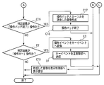
まず、図3に示すフローチャートを参照して、タッチパッド制御部23がタッチパッド12に対して行われた操作を検出し、検出した操作をこの操作に対応する制御部に送信する動作について説明する。タッチパッド制御部23は、所定の時間間隔で、又は、タッチパッド12が操作されたことによる割り込みが生じると、図3に示す動作を開始する。タッチパッド制御部23は、タッチパッド12に対する操作の検出、つまりタッチパッド操作イベントの検出を行う(ステップA1)。ここで、タッチパッド操作イベントは、タッチパッド12が操作されたことを示すと共に、操作された位置を示す座標を含んでいる。このため、例えばタッチパッド12に指等が触れた場合、タッチパッド制御部23は、接触された位置の座標を検出する。又は、例えば、タッチパッド12に指等が触れたまま移動した場合、タッチパッド制御部23は、接触された複数の位置の各座標の順序がわかるように時系列で検出する。
次に、タッチパッド制御部23は、LCD11に操作パッドが表示されているか否かを判断する(ステップA2)。LCD11に操作パッドが表示されているか否かは、例えば操作パッド/ポインタ制御部24が起動しているか否かに対応するので、主制御部20のタスク管理情報を参照することによって判断する。
操作パッドが表示されている場合(ステップA2でYESと判断)、タッチパッド制御部23は、上記タッチパッド操作イベントが操作パッドの表示領域内で生じたものであるか否かを判断する(ステップA3)。操作パッドの表示領域の位置は、操作パッド/ポインタ制御部24によって制御され、主制御部20に通知されて、主制御部20にリソース管理情報の一部として記憶される。このため、上記リソース管理情報を参照することによって得られる。
ここで、表示領域内であった場合(ステップA3でYESと判断)、タッチパッド制御部23は、上記タッチパッド操作イベントを操作パッド/ポインタ制御部24に送信して(ステップA4)、動作を終了する。
表示領域以外であった場合(ステップA3でNOと判断)、タッチパッド制御部23は、上記タッチパッド操作イベントを主制御部20に送信して(ステップA7)、動作を終了する。一方、操作パッドが表示されていない場合(ステップA2でNOと判断)、上記タッチパッド操作イベントが操作パッドを表示させるアクションイベントか否かを判断する(ステップA5)。
操作パッド表示アクションイベントの場合(ステップA5でYESと判断)、タッチパッド制御部23は、操作パッド/ポインタ制御部24を起動させて操作パッドを表示させて(ステップA6)、動作を終了する。一方、上記アクションイベント以外の場合(ステップA5でNOと判断)、主制御部20に上記タッチパッド操作イベントを送信して(ステップA7)、動作を終了する。
ここで、操作パッドを表示させる上記アクションイベントについて説明する。図4は、操作パッドが表示されていないLCD11の表示状態を示すもので、一例として、ランチャーメニュー部が動作している様子を示す。この図に示すLCD11の表示は、主制御部20によって作成された画像であり、表示画面左上には第1の特定機能表示11aが表示され、表示画面右上には第2の特定機能表示11bが表示され、残る領域にはランチャーメニュー部に対応する6つのアイコンが表示される。
このように操作パッドが表示されない状態で、第1の特定機能表示11a、第2の特定機能表示11b又は6つのアイコンのいずれかに対してタッチパッド操作イベントが発生すると、タッチパッド操作イベントは、ステップA7の動作で説明したように、主制御部20に送信される。また、第1の特定機能表示11a、又は第2の特定機能表示11bに対する操作でタッチパッド操作イベントが発生した場合、主制御部20によって、動作しているアプリケーションに依存しない共通な制御が行われる。この共通な制御は、例えば、動作しているアプリケーションの終了する制御や、特定のアプリケーションを起動する制御、主制御部20の機能メニューを表示する制御である。
そして、6つのアイコン表示のいずれかが操作された場合、主制御部20は、動作しているアプリケーション、即ち、ランチャーメニュー部に、タッチパッド操作イベントを送信する。ランチャーメニュー部は、与えられたタッチパッド操作イベントに従って、操作されたアイコンに対応するアプリケーションを起動する制御を行う。
操作パッドを表示させるアクションイベントは、操作領域14に指40が接触し、その接触が保たれたまま、指40がLCD11上に移動する操作により発生する。言い換えると、使用者が、指40を操作領域14に接触させ、指40をタッチパッド12に接触させたまま、その接触した位置をLCD11上に移動させることにより発生させる。なお、移動通信装置1は、右手で保持されており、指40は、右手の親指である。
次に、図5乃至図8を参照して、操作パッド/ポインタ制御部24による操作パッドの起動/移動/終了処理、及び、操作パッドを介した入力処理について説明する。
操作パッドが表示されていない場合には、ステップA6で説明したように、操作パッドを表示させる処理を行う。その詳細を図5のフローチャートに示す。操作パッド/ポインタ制御部24は、タッチパッド制御部23から要求があった場合、図5に示す処理を開始し、タッチパッド制御部23から操作パッドを表示する要求を受信して(ステップB1)、操作パッドに係る処理を開始する(ステップB2)。
次に、操作パッド/ポインタ制御部24は、操作パッドとカーソルを含む画像データを作成し(ステップB3)、この画像データを表示制御部25に出力して表示を要求する(ステップB4)。最後に、操作パッドがアイコン化されているか否かを示すアイコンフラグをリセットし(ステップB5)、当該処理を終了する。アイコンフラグは、リセットによって、操作パッドがアイコン化されていないことを示し、セットによって、アイコン化されていることを示す。
一方、操作パッドが表示されている場合には、ステップA4で説明したように、操作パッド/ポインタ制御部24は、タッチパッド制御部23からタッチパッド操作イベントを受信して、このタッチパッド操作イベントに応じた制御を行う。例えば、操作パッドをアイコン化/非アイコン化、又はカーソルの表示位置の移動、操作パッドの表示位置の移動、操作パッドの表示の終了等の表示制御や、タッチパッド12が操作されたことを主制御部20に通知したりする。
まず、図6を参照して、カーソル51と、操作パッド52について説明する。これらは、いずれもLCD11に表示される画像であって、カーソル51は、LCD11の表示画面の位置を識別するポインタであり矢印の図形である。なお、その図形は矢印に限らない。操作パッド52は、タップイベント送出ボタン53と、操作パッド移動領域54と、アイコン化ボタン55と、これら以外の部分であるカーソル操作領域56とを備えた画像である。
タップイベント送出ボタン53は、指40によって操作される(タップ)と、タッチパッド制御部23によってタップイベント送信操作イベントが生成され、主制御部20に出力される。このタップイベント送信操作イベントは、操作パッド52とは無関係に、カーソル51が示す位置を選択したことを示すものである。即ち、タップイベント送出ボタン53は、カーソル51が示す位置をタップすることと同じ効果のイベントを生成するためのボタンである。
なお、このイベントに対応して、主制御部20は、例えば、新たにアプリケーションを起動し、主制御部20が、表示する画像を変更することがある。ただし、この場合、表示されている操作パッド52に何ら変更はなく、引き続きその操作パッド52を介した入力が可能である。操作パッド52は、アプリケーション等に依存しない、汎用の入力のための手段である。例えば、新たに起動されたアプリケーションにおいても、引き続き用いられる方が適切だからである。
操作パッド移動領域54に、指40が接触されたまま移動すると、これを検出したタッチパッド制御部23は、操作パッド移動操作イベントを生成する。即ち、操作パッド移動領域54は、操作パッド52を表示する位置を、指40の移動に追従して移動させるために用いる領域である。
なお、指40が操作パッド移動領域54に接触したまま、LCD11の表示画面の外である操作領域14に移動した場合、タッチパッド制御部23が操作パッド終了操作イベントを生成し、操作パッド52の表示が消去される。言い換えると、操作パッド終了操作イベントは、使用者が、指40を操作パッド移動領域54に接触させ、接触を続けたまま、指40をLCD11外のタッチパッド12に滑らせる操作により発生できる。このとき、操作パッド52の少なくとも一部は、LCD11の表示画面外に出ることになり、上記一部はLCD11に表示されない。
アイコン化ボタン55は、指40がこのボタンに接触すると、タッチパッド制御部23によって操作パッドアイコン化操作イベントが生成され、操作パッド52をアイコン化するためのボタンである。カーソル操作領域56は、指40がこの領域に接触すると、タッチパッド制御部23によってカーソル移動操作イベントが生成され、操作パッド52に接触した指40の動きに応動して、カーソル51の表示位置を上下左右に移動させるための領域である。
アイコン化された操作パッドについて説明する。図7は、アイコン化された操作パッド57を表示するLCD11を示すものである。この図に示すように、アイコン化された操作パッド57は、小さいので、それに含まれるボタンや、領域に対して操作することはできない。そこで、操作パッド52に代わってアイコン化した操作パッド57を表示している場合、操作パッド/ポインタ制御部24は、カーソル51を表示しない。操作パッド57に指40が接触すると、タッチパッド制御部23が操作イベントを生成する。そして、この操作イベントが生成されることを契機にして、アイコン化された操作パッド57は、非アイコン化され、代わりに、カーソル51と操作パッド52とが表示される。
図8に示すフローチャートを参照して、操作パッド52が表示されている場合の操作パッド/ポインタ制御部24の動作について説明する。操作パッド/ポインタ制御部24は、タッチパッド制御部23からタッチパッド操作イベントを受信すると、図8に示す処理を開始する。まず、操作パッド/ポインタ制御部24は、タッチパッド制御部23からタッチパッド操作イベントを受信し(ステップC1)、アイコンフラグがセットされているか否かを判断する(ステップC2)。
アイコンフラグがセットされている場合(ステップC2でYESと判断)、操作パッド/ポインタ制御部24は、非アイコン化状態に遷移し(ステップC3)、アイコンフラグをリセットする(ステップC4)。更に、操作パッド/ポインタ制御部24は、操作パッド52のアイコンである操作パッド57に代えて、操作パッド52及びカーソル51を表示する画像データを作成し(ステップC10)、この画像データを表示制御部25に与えることで、操作パッド52及びカーソル51の画像を表示する要求を行って(ステップC19)、当該処理を終了する。
アイコンフラグがリセットされている場合(ステップC2でNOと判断)、操作パッド/ポインタ制御部24は、タッチパッド制御部23から受信したタッチパッド操作イベントの判定を行う(ステップC5)。この判定では、タッチパッド操作イベントが、カーソルを移動する操作、操作パッドを移動する操作、タップイベントを送信する操作、操作パッドをアイコン化する操作、操作パッドの表示を終了する操作、又は、それ以外のいずれを示すものであるかが判定される。上記操作の判定基準となる具体的なタッチ操作の内容に関しては、図6を参照して、前述した通りである。
判定結果がカーソルを移動する操作の場合(ステップC6でYESと判定)、操作パッド/ポインタ制御部24は、タッチパッド操作イベントに含まれる座標の情報に基づいて、移動後のカーソル51の表示座標を計算し(ステップC7)、その計算結果に従った位置にカーソル51を表示させるように、ステップC10において、操作パッド52とカーソル51とが含まれる画像データを作成する。なお、このカーソル51を移動させる操作は、指40をカーソル操作領域56上で移動させることによって行う。このため、指40がカーソル操作領域56に触れている場合、ステップC7及びステップC10の処理が継続して行われることになる。
判定結果が操作パッドを移動する操作である場合(ステップC8でYESと判定)、操作パッド/ポインタ制御部24は、タッチパッド操作イベントに含まれる座標の情報に基づいて、移動後の操作パッド52の表示座標を計算し(ステップC9)、その計算結果に従った位置に操作パッド52を表示させるように、ステップC10において、操作パッド52とカーソル51とが含まれる画像データを作成する。なお、この操作パッド52を移動させる操作は、操作パッド移動領域54に触れた指40を触れたまま移動させることによって行う。このため、指40が操作パッド移動領域54に触れている場合、ステップC9及びステップC10の処理が継続して行われることになる。
判定結果がタップイベントを送信する操作の場合(ステップC11でYESと判定)、操作パッド/ポインタ制御部24は、カーソル51の表示位置の座標の情報を含むタップイベントを主制御部20に送信する(ステップC12)。判定結果が操作パッドをアイコン化する操作の場合(ステップC13でYESと判定)、操作パッド/ポインタ制御部24は、アイコン化されていることを示すアイコンフラグをセットし(ステップC14)、操作パッド52に代わってアイコン化された操作パッド57を表示する画像データを作成する(ステップC15)。そして、操作パッド/ポインタ制御部24は、この画像データを表示制御部25に与えることで、操作パッド57を表示する要求を行って(ステップC19)、当該処理を終了する。
判定結果が操作パッドの表示を終了する操作である場合(ステップC16でYESと判定)、操作パッド/ポインタ制御部24は、操作パッド52とカーソル51とを表示しない画像データを作成し(ステップC17)、操作パッドを介した入力処理を終了する(ステップC18)。そして、操作パッド/ポインタ制御部24は、上記画像データを表示制御部25に与えることで、操作パッド52とカーソル51とを表示しない画像を表示させる要求を行って(ステップC19)、操作パッド52とカーソル51とを消去し、当該処理を終了する。判定結果がそれ以外の場合(ステップC16でNOと判定)には、不要なイベントであると判定し、処理は行わずに当該処理を終了する。
次に、図9に示すフローチャートを参照して、表示制御部25が主制御部20から表示するように要求された画像と、操作パッド/ポインタ制御部24から表示するように要求された画像とを合成して、この合成した画像をLCD11に表示する制御について説明する。
表示制御部25は、主制御部20又は操作パッド/ポインタ制御部24から表示する要求が送信されると、図9に示す処理を開始する。表示制御部25は、上記要求を受け付けて(ステップD1)、主制御部20から表示するように要求された画像と、操作パッド/ポインタ制御部24から表示するように要求された画像とを合成した画像を作成し(ステップD2)、この作成した合成画像をLCD11に表示する(ステップD3)。画像の合成は、例えば、αブレンドにより行う。
合成された画像の一例について、図10を参照して説明する。図10に示す合成画像58は、主制御部20によって作成された図4に示す画像と、操作パッド/ポインタ制御部24で作成された図6に示す画像とをαブレンド処理により合成した画像である。この画像に示すように、主制御部20によって作成された画像が視認可能で、操作パッド52を用いたユーザインターフェースが提供される。
次に、上述した各タッチ操作(カーソルを移動する操作、操作パッドを移動する操作、タップイベントを送信する操作、操作パッドをアイコン化する操作、及び、操作パッドの表示を終了する操作)について、図面を参照して具体的に説明する。
図11は、カーソルを移動する操作の例を説明する図である。カーソル操作領域56(操作パッド52のうち、タップイベント送出ボタン53、操作パッド移動領域54及びアイコン化ボタン55以外の領域。図6参照。)上に置いた指40を滑らせると、操作パッド/ポインタ制御部24及び表示制御部25によってカーソル51が移動する表示がなされる。例えば図11では、指40を左に滑らせることで、カーソルが図10に示す位置より左に移動する表示がなされる。このように、カーソル51は、カーソル操作領域56上で指40を滑らせた方向と同方向へ移動する。このような操作に基づくタッチパッド操作イベントがタッチパッド制御部23から与えられた場合、操作パッド/ポインタ制御部24は、図8のステップC5の判定処理により、カーソルを移動させる操作が発生したと判定する。
図12は、操作パッド52を移動する操作の例を説明する図である。操作パッド52上の操作パッド移動領域54に指40で触れ、そのまま指40をタッチパッド12上で滑らせると、操作パッド/ポインタ制御部24及び表示制御部25によって操作パッド52を移動する表示がなされる。例えば図12では、指40を下に滑らせることで、操作パッド52が図10に示す位置より下に移動する表示がなされる。このように、操作パッド52は、指40の動作に応じて移動する。このような操作に基づくタッチパッド操作イベントがタッチパッド制御部23から与えられた場合、操作パッド/ポインタ制御部24は、図8のステップC5の判定処理により、操作パッド52を移動させる操作が発生したと判定する。
図13は、タップイベントを送出する操作の例を説明する図である。タップイベント送出ボタン53を指40でタッチ(タップ)すると、この操作に応動してタッチパッド制御部23により生成されたタッチパッド操作イベントが、操作パッド/ポインタ制御部24に与えられる。これに対して、操作パッド/ポインタ制御部24は、図8のステップ5Cの判定処理により、タップイベント送出操作が発生したと判定する。これにより操作パッド/ポインタ制御部24は、操作パッド52とは無関係に、カーソル51が示す位置をタップした旨を示すイベントを、主制御部20に送信する。これにより主制御部20は、カーソル51が示す位置に例えばアイコンが表示されていると、アプリケーション部29が有するツール部のうち、上記アイコンに対応するツール部を起動する。
図14Aおよび図14Bは、操作パッド52をアイコン化する操作の例を説明する図である。図14Aは、操作パッド52のアイコン化ボタン55を指40でタップする操作を示したものである。アイコン化ボタン55を指40でタップすることにより、操作パッド52はアイコン化される。このような操作に基づくタッチパッド操作イベントがタッチパッド制御部23から与えられた場合、操作パッド/ポインタ制御部24は、図8のステップC5の判定処理により、操作パッド52をアイコン化させる操作が発生したと判定する。図14Bは、操作パッド52に代わって、アイコン化された操作パッド57が表示された状態を示したものである。また反対に、非アイコン化する場合、即ち操作パッド52を表示させる場合には、操作パッド57を指40でタッチ(タップ)すればよい。
図15は、操作パッド52の表示を終了する操作の例を説明する図である。操作パッド52上の操作パッド移動領域54に指40で触れた後、そのまま指40をタッチパッド12上で下に滑らせ、操作領域14まで指40を移動すると、操作パッド52の表示とカーソル51の表示とを終了させることができる。このような操作に基づくタッチパッド操作イベントがタッチパッド制御部23から与えられた場合、操作パッド/ポインタ制御部24は、図8のステップC5の判定処理により、操作パッド52の表示を終了する操作が発生したと判定する。
言い換えると、LCD11に表示されている操作パッド移動領域54に、使用者が指40を接触させ、そのまま指40を滑らせてLCD11外へ移動させて、操作領域14に触れることによって、操作パッド52の表示とカーソル51の表示とを終了させることができる。
なぜなら、このアクションをタッチパッド12の検出結果からタッチパッド制御部23が検出し、タッチパッド操作イベントとして操作パッド/ポインタ制御部24に通知する。これに対して操作パッド/ポインタ制御部24は、ステップC16において、操作パッドの表示を終了するアクションと判定し、表示制御部25を制御して、操作パッド52の表示を終了する。
また反対の操作により、操作パッド52を表示させるようにしてもよい。即ち、使用者が指40を操作領域14に触れたまま、LCD11上に滑らせるアクションを行う。すると、このアクションをタッチパッド12の検出結果からタッチパッド制御部23が検出し、タッチパッド操作イベントとして操作パッド/ポインタ制御部24に通知する。これに対して操作パッド/ポインタ制御部24は、操作パッドの表示を開始するアクションと判定し、表示制御部25を制御して、操作パッド52を表示する。
(第2の実施形態)
第2の実施形態に係る情報処理装置が適用された移動通信装置1は、図1及び図2に示した第1の実施形態で説明した移動通信装置1と、見かけ上類似した構成である。そこで、第2の実施形態に係る情報処理装置が適用された移動通信装置1の構成については、第1の実施形態に係る移動通信装置1と同じ部分には同一の符号を付して説明する。なお、以下の説明では、相違点を中心に説明し、特に説明しない点については、第1の実施形態に係る移動通信装置1と同様であるものとする。
第2の実施形態に係る情報処理装置が適用された移動通信装置1は、図1及び図2に示した第1の実施形態で説明した移動通信装置1と、見かけ上類似した構成である。そこで、第2の実施形態に係る情報処理装置が適用された移動通信装置1の構成については、第1の実施形態に係る移動通信装置1と同じ部分には同一の符号を付して説明する。なお、以下の説明では、相違点を中心に説明し、特に説明しない点については、第1の実施形態に係る移動通信装置1と同様であるものとする。
第2の実施形態に係る情報処理装置が適用された移動通信装置1は、第1の実施形態の移動通信装置1と比べて、操作パッドと、操作パッドを介した使用者操作を処理する操作パッド/ポインタ制御部24の動作が一部異なっている。
まず、図16を参照して、第2の実施形態に係る移動通信装置1で表示される操作パッド70について説明する。操作パッド70は、タップイベント送出ボタン53と、操作パッド移動領域54と、アイコン化ボタン55と備えた画像であり、この他に、十字キーボタン(上キーボタン71a、下キーボタン71b、右キーボタン71c、及び、左キーボタン71d)と、決定キーボタン72と、これら以外の部分であるカーソル操作領域56とを備えた画像である。なお、十字キーボタンには、矢印図形が表示されているように図示したが、矢印図形以外の図形でもよい。
十字キーボタンと、決定キーボタン72とは、例えば、アプリケーションによってLCD11に表示されたアイテムの1つを選択し、選択されたアイテムに対応する動作をアプリケーションにさせるために用いられる。即ち、アプリケーションは、アイテムを表示し、表示されたアイテムの中の1つのアイテムを選択する。ここで、アイテムが選択されていることを使用者が認識できるよう識別可能にするために、選択されたアイテムは、他のアイテムと区別できるように強調されて表示がされる。以下の説明では、この強調された表示を、フォーカス表示と呼ぶ。
そして、上キーボタン71aが操作されると、アプリケーションは、選択されたアイテムの上方に表示されたアイテムを選択し、下キーボタン71bが操作されると、選択されたアイテムの下方に表示されたアイテムを選択する。右キーボタン71cが操作されると、アプリケーションは、選択されたアイテムの右方に表示されたアイテムを選択し、左キーボタン71dが操作されると、選択されたアイテムの左方に表示されたアイテムを選択する。そして、決定キーボタン72が操作されると、アプリケーションは、選択されたアイテム(フォーカスが当てられたアイテム)に対応する動作をする。
このように、十字キーボタンや決定キーボタン72を用いた入力と、第1の実施形態で説明したカーソル51やタップイベント送出ボタン53を用いた入力とのいずれの入力であっても、種々のアプリケーションを制御することができる。
しかしながら、例えば、ランチャーメニュー部によって表示される6つのアイコンは、上下左右に整然と配置されているため、十字キーボタンと、決定キーボタン72とによる入力が適している。一方、例えば、ブラウザ部によって表示されているWebコンテンツに含まれるアンカーは、整然と配置されていないことが多いため、カーソル51やタップイベント送出ボタン53を用いた入力が適している。
これらの2つの入力方法は、アプリケーションや、表示される内容に応じて、また、使用者の嗜好によって、適宜使い分けられるべきことである。第2の実施形態に係る移動通信装置1は、2つの入力方法を備えるため、使用者は、常に希望する方法を用いることができる。
次に、図17及び図18に示すフローチャートを参照して、操作パッド70が表示されている場合の操作パッド/ポインタ制御部24の動作について説明する。なお、図8に示したフローチャートと同じ処理を行うステップについては、同じ符号を付し、その説明を省略する。
操作パッド/ポインタ制御部24は、図8のステップC5に代えて、ステップE1を実施する。ステップE1において操作パッド/ポインタ制御部24は、タッチパッド制御部23から受信したタッチパッド操作イベントの判定を行う。具体的には、操作パッド/ポインタ制御部24は、タッチパッド操作イベントが、カーソルを移動する操作、操作パッドを移動する操作、タップイベントを送信する操作、操作パッドをアイコン化する操作、操作パッドの表示を終了する操作及び、操作キーに対する操作のうち、いずれを示すものであるかを判定する。ここで、操作キーに対する操作とは、十字キーボタンに対する操作、又は決定キーボタン72に対する操作を意味しており、タッチパッド操作イベントに含まれる、操作された位置を示す座標に基づいて、いずれの操作が行われたのかを判断する。
また第2の実施形態では、ステップC16で、タッチパッド操作イベントが操作パッドの表示を終了する操作ではないと判定した場合、操作パッド/ポインタ制御部24は、ステップE2を実行する。ステップE2において操作パッド/ポインタ制御部24は、判定結果が操作キーに対する操作であるか否かを判定する。ここで、判定結果が操作キーに対する操作であると判定した場合(ステップE2でYESと判定)、操作パッド/ポインタ制御部24は、タッチパッド操作イベントに含まれる座標に対応する操作キーが操作されたことを示すキーイベントを生成し(ステップE3)、このキーイベントを主制御部20に送信して(ステップE4)、動作を終了する。これに対して主制御部20は、表示制御部25を制御して、上記操作キーに対する操作に応じて、フォーカス表示74の表示位置を移動させる。なお、上記座標が十字キーボタン71a~71dのいずれかに一致する場合、一致するボタンに応じて主制御部20が、フォーカス表示を上下左右のいずれかのアイテムに移動させる。
ここで、図19を参照して、表示制御部25が主制御部20から表示するように要求された画像と、操作パッド/ポインタ制御部24から表示するように要求された画像とを合成して、この合成した画像をLCD11に表示する制御について説明する。
図19に示す合成画像73は、図10に示した合成画像58と比較して、操作パッド52に代えて、操作パッド70を含んでいる。また合成画像73は、主制御部20によって、フォーカス表示74が合成されている。
フォーカス表示74は、アプリケーションによって表示されるアイテムのうち、十字キーボタンの操作によって選択されたアイテムを、他のアイテムと区別できるように、強調して表示するポインタである。図19では、フォーカス表示74は、長方形の太枠であって、選択されたアイテムを囲っている。なお、第1の特定機能表示11aや、第2の特定機能表示11bは、アプリケーションによって表示されるものではないため、フォーカス表示74が強調する対象にはならない。フォーカス表示74は、長方形に限るものではなく、また任意の色を設定したり、点滅表示させるようにしても良い。
また、以上の説明では、主制御部20が、フォーカス表示74を作成し、表示する位置を制御するとして説明したが、これに限るものではない。例えば、主制御部20に代わって、操作パッド/ポインタ制御部24がその役割を担うようにしても良い。
(第3の実施形態)
第3の実施形態に係る情報処理装置が適用された移動通信装置1は、図1及び図2に示した第1の実施形態の移動通信装置1及び第2の実施形態の移動通信装置1と類似している。そこで、第1及び第2の実施形態に係る移動通信装置1と同じ部分には同一の符号を付し重複する説明を省略し、相違点を説明する。
第3の実施形態に係る情報処理装置が適用された移動通信装置1は、図1及び図2に示した第1の実施形態の移動通信装置1及び第2の実施形態の移動通信装置1と類似している。そこで、第1及び第2の実施形態に係る移動通信装置1と同じ部分には同一の符号を付し重複する説明を省略し、相違点を説明する。
第3の実施形態に係る情報処理装置が適用された移動通信装置1は、第1及び第2の実施形態の移動通信装置1と比べて、操作パッドと、操作パッドを介した使用者操作を処理する操作パッド/ポインタ制御部24の動作が一部が異なっている。
まず、図20A、図20B、図20Cを参照して、第3の実施形態に係る移動通信装置1で表示される操作パッドについて説明する。この実施形態では、第1~第3の3種類の操作パッドを備え、選択的に1つの操作パッドを表示するようにしたものである。なお、操作パッドが表示された状態から非表示状態になった後、所定の操作が為されることで新たに表示される操作パッドは、非表示になる直前に表示されていた操作パッドと同じ種類の操作パッドである。この実施形態では、予め備えた複数の操作パッドの中の1つを選択的に表示するようにしているため、各操作パッドを表示する制御は単純かつ明瞭である。このため、使用者は、誤操作する可能性が小さい。
第1の操作パッド80は、図20Aに示すように、操作パッド移動領域54と、十字キーボタン(上キーボタン71a、下キーボタン71b、右キーボタン71c、及び、左キーボタン71dからなる。)と、決定キーボタン72と、第1の特定機能表示81aと、第2の特定機能表示81bと、操作パッド切替ボタン82とを備えた画像である。
第1の特定機能表示81aと、第2の特定機能表示81bとは、それぞれ、図4に示した第1の特定機能表示11aと、第2の特定機能表示11bに相当するものである。第1の特定機能表示11aと第2の特定機能表示11bは、LCD11の上角に表示され、フォーカス表示74の対象外である。このため、移動通信装置1を片手で使用している場合に、第1の特定機能表示11aや第2の特定機能表示11bに指40で触れることが難しく、指40で触れるためには、移動通信装置1を持ちかえる必要がある。これに対して、第1の特定機能表示81a及び第2の特定機能表示81bは、第1の操作パッド80内に表示されているため、移動通信装置1を片手で使用している場合でも、容易に指40で触れることができる。
操作パッド切替ボタン82は、長押し操作されると、主制御部20の制御によって、第1の操作パッド80に代えて、第2の操作パッドを表示させるためのソフトウェアキーである。なお、長押し操作とは、所定時間以上、連続して接触する操作である。
なお、第1の操作パッド80が表示されている場合、第2の実施形態の操作パッド70と同様に、主制御部20の制御によってフォーカス表示74が表示され、その表示位置が制御される。
第2の操作パッド83は、図20Bに示すように、タップイベント送出ボタン53と、操作パッド移動領域54と、操作パッド切替ボタン82と、スクロールバー84と、これら以外の部分であるカーソル操作領域56とを備えた画像である。操作パッド切替ボタン82は、長押し操作されると、主制御部20の制御によって、第2の操作パッド83に代えて、第3の操作パッドを表示させるためのソフトウェアキーである。主制御部20は、第2の操作パッド83を表示する場合には、カーソル51も表示するように制御する。
スクロールバー84は、第2の操作パッド83の右辺に沿った垂直バーと、第2の操作パッド83の下辺に沿った水平バーとからなり、垂直バー上で指40を移動させると、表示されている画像が主制御部20によって縦方向にスクロール表示され、また、水平バー上で指40を移動させると、表示されている画像が主制御部20によって横方向にスクロール表示される。
なお、操作パッド切替ボタン82は、表示されている操作パッドの種類に関係なく、長押し操作が必要である。その理由は、主に、第2の操作パッド83にある。第2の操作パッド83では、指40がカーソル操作領域56上で広く移動するため、誤って指40が操作パッド切替ボタン82に接触しただけでは、操作パッドの切り替えが発生しないように、操作パッド切替ボタン82長押し操作で動作するようにしている。また操作パッド毎に、操作パッド切替ボタン82に対する操作が異なると、使用者が混乱するので、長押し操作に統一している。
第3の操作パッド85は、図20Cに示すように、操作パッド移動領域54と、操作パッド切替ボタン82と、第1の機能表示86aと、第2の機能表示86bとを備えた画像である。第1の機能表示86aと、第2の機能表示86bとは、操作されると、それぞれ対応づけられた所定のアプリケーションを起動するために用いられる。操作パッド切替ボタン82は、長押し操作されると、主制御部20の制御によって、第3の操作パッド85に代えて、第1の操作パッド80を表示させるためのソフトウェアキーである。
ここで、第1~第3の操作パッド80、83、85の大きさは、互いに異なっても良い。第2の操作パッド83は、カーソル操作領域56を有するため、大きいことが好ましい。ただし、主制御部20が作成した画像と、操作パッドとは合成されてLCD11に表示されるため、操作パッドによって、いくらかの見難さを伴うことが避けられない。このため、いずれの操作パッドであっても、指40の移動によって触れることが可能な大きさであればよく、この大きさを超えて大きくしないことが好ましい。
一方、第3の操作パッド85は、表示する内容が少ないので、小さく表示することができる。ただし、第1~第3の操作パッド80、83、85のいずれにおいても、操作パッド切替ボタン82は、LCD11の表示画面の共通の位置に表示される。これにより、容易に連続して第1~第3の操作パッド80、83、85を切り替えることができる。
次に、図21及び図22に示すフローチャートを参照して、第1~第3の操作パッド80、83、85が表示されている場合の操作パッド/ポインタ制御部24の動作について説明する。なお、図8、図17及び図18に示したフローチャートと同じ処理を行うステップについては、同じ符号を付し、その説明を省略する。
なお、第3の実施形態に係る操作パッドは、アイコン化しない。そこで、操作パッド/ポインタ制御部24は、アイコン化して表示するための動作及び非アイコン化して表示するための動作である、図8のステップC2~ステップC4、及び、ステップC13~ステップC15の動作は行わない。
操作パッド/ポインタ制御部24は、ステップC5に代えて、ステップF1を実施する。ステップF1において操作パッド/ポインタ制御部24は、タッチパッド制御部23から受信したタッチパッド操作イベントの判定を行う。具体的には、操作パッド/ポインタ制御部24は、タッチパッド操作イベントが、スクロールバーに対する操作、カーソルを移動する操作、操作パッドを移動する操作、タップイベントを送信する操作、操作パッドの表示を終了する操作、操作キーに対する操作、操作パッドを切り替える操作、表示している機能を実行する操作のうち、いずれを示すものであるかを判定する。操作パッドをアイコン化する操作であるか否かについては判定しない。
ここで、スクロールバーに対する操作とは、スクロールバー84に対する操作のことである。また、操作パッドを切り替える操作とは、操作パッド切替ボタン82に対する操作のことである。そして、表示している機能を実行させる操作とは、第1、第2の特定機能表示81a、81b、及び、第1、第2の機能表示86a、86bに対する操作である。
判定結果がスクロールバーに対する操作である場合(ステップF2でYESと判定。この判定は、第2の操作パッド83が表示されている場合に限って行われる。)、操作パッド/ポインタ制御部24は、主制御部20に対して、LCD11に表示している画像を、水平方向又は垂直方向にスクロール表示するように指示して(ステップF3)、動作を終了する。これにより、主制御部20は、表示制御部25を制御して、水平バーが操作された場合には、LCD11に表示している画像を水平方向にスクロール表示させ、一方、垂直バーが操作された場合には、LCD11に表示している画像を垂直方向にスクロール表示させる。
判定結果がカーソルを移動する操作の場合(ステップC6でYESと判定。この判定は、第2の操作パッド83が表示されている場合に限って行われる。)、操作パッド/ポインタ制御部24は、ステップC7に代えて、ステップF4~F7を実施する。
即ち、操作パッド/ポインタ制御部24は、主制御部20に対して操作パッド移動領域54の表示形態を変更する指示を行う(ステップF4)。これにより、主制御部20は、表示制御部25を制御して、上記表示形態を変更する。この表示形態の変更は、カーソル操作領域56を介した操作が行われたことを使用者に示すためである。例えば、色や濃さ、デザイン等を変更したり、又は表示を点滅させる。そして、操作パッド/ポインタ制御部24は、ステップC7と同様にして、カーソル51の表示座標を計算する(ステップF5)。
続いて、操作パッド/ポインタ制御部24は、タッチパッド操作イベントに含まれる座標の情報に基づいて、指40が接触されている位置が、第2の操作パッド83の外であるか否かを判定する(ステップF6)。外であると判定した場合、言い換えると、指40が接触されたまま第2の操作パッド83の外に移動した場合、この旨を操作パッド/ポインタ制御部24は、主制御部20に通知する(ステップF7)。これにより主制御部20は、バイブレータ(図示せず)を振動させて、上記位置が第2の操作パッド83の外であり、操作が無効であることを使用者に報知する。一方、外でないと判定された場合、上記報知を行うことなく、ステップC10に移行して、操作パッドと、移動したカーソル51が合成された画像を表示する。
なお、ステップF7では、上記報知に代えて、操作パッド/ポインタ制御部24が、指40が接触している位置に追従して、第2の操作パッド83を移動させて表示するようにしても良い。即ち、この場合、前述とは異なり、第2の操作パッド83外への指40の移動に伴う操作が受け付けられている。また、このような第2の操作パッド83が表示される位置の移動に合わせて、第1の操作パッド80及び第3の操作パッド85を表示する位置も同様に移動させるようにしてもよい。また、このような第1乃至第3の操作パッドの表示位置を変更しても、操作パッド切替ボタン82の表示位置は変更せずに、同じ位置に表示するように制御してもよい。なお、これらの制御は、操作パッド/ポインタ制御部24が主制御部20に対して指示を与えることで、主制御部20と表示制御部25が行う。
判定結果が操作キーに対する操作でない場合(ステップE2でNOと判定)、操作パッド/ポインタ制御部24は、ステップF8に移行する。そして、判定結果が操作パッドを切り替える操作である場合(ステップF8でYESと判定)、操作パッド/ポインタ制御部24は、現在表示している操作パッドに代えて、次順の種類の操作パッドを表示する画像を作成し、これを表示制御部25に出力(ステップF9)、ステップC19に移行する。カーソル51は、第2の操作パッド83を表示する場合にのみ表示される。
また、判定結果が、表示している機能を実行する操作である場合(ステップF10でYESと判定。この判定は、第1の操作パッド80か、第3の操作パッド85が表示されている場合に限って行われる。)、操作パッド/ポインタ制御部24は、操作された機能を主制御部20に通知し、これにより主制御部20が、通知された機能に対応する機能を実行し(ステップF11)、当該処理を終了する。例えば、操作された表示が第1、第2の特定機能表示81a、81bである場合、主制御部20に対して、それぞれ、第1、第2の特定機能表示81a、81bが操作されたイベントが発生した旨を送信する。一方、第1、第2の機能表示86a、86bが操作された場合、主制御部20に対して、それぞれに定められた所定のアプリケーションを起動するように指示する。
次に、図23~図25を参照して、表示制御部25によって生成された合成画像の表示例について説明する。なお、表示制御部25は、主制御部20から表示要求された画像と、操作パッド/ポインタ制御部24から表示要求された画像を合成することで上記合成画像を生成する。
第1の操作パッド80及びフォーカス表示74を含む合成画像91を図23に例示する。フォーカス表示74は、主制御部20によって作成される。第2の操作パッド83及びカーソル51を含む合成画像92を図24に例示する。更に、第3の操作パッド85を含む合成画像93を、図25に例示する。第3の操作パッド85は、第1の特定機能表示81a又は第2の特定機能表示81bに対応づけられた機能を素早く起動するためのパッドであり、カーソル51及びフォーカス表示74は、表示しない。
次に、図26A、図26B、図26Cを参照して、図20A、図20B、図20Cに示した第1~第3の操作パッド80、83、85の変形例である第1の操作パッド80-2、第2の操作パッド83-2、第3の操作パッド85-2について説明する。第1の操作パッド80-2、第2の操作パッド83-2、第3の操作パッド85-2は、それぞれ、第1~第3の操作パッド80、83、85と比較して、操作パッド切替ボタン82の位置が異なる。
即ち、第1~第3の操作パッド80、83、85では、操作パッド切替ボタン82が操作パッドの右下部に表示するようにしていたが、第1~第3の操作パッド80-2、83-2、85-2では、左下部に表示するようにしている。また、第2の操作パッド83-2においては、第2の操作パッド83と比較して、操作パッド切替ボタン82の位置の変更に伴い、スクロールバー84の表示位置を変更するとともに、タップイベント送出ボタン53の位置も変更している。その他の操作に用いられるボタン及び領域については、位置を変更していない。
第1~第3の操作パッド80、83、85又は第1~第3の操作パッド80-2、83-2、85-2のどちらのグループが用いられるかは、使用者が利き手や嗜好に応じて選択する。なお、いずれのグループを選択した場合でも、操作パッドの表示を終了し、再び操作パッドを表示する場合には、同じグループの操作パッドが表示される。また、第1~第3の操作パッド80-2、83-2、85-2のグループを用いる場合、いずれの操作パッドにおいても、操作パッド切替ボタン82はLCD11の表示画面の共通する位置に表示されるように、主制御部20が制御する。
なお、第3の実施形態において、第1~第3の操作パッド80、83、85の3種類を選択的に用いるものとして説明したが、これに限るものではなく、任意の2種類であっても良い。
(その他の実施形態)
操作パッド/ポインタ制御部24は、テストモードで動作する。テストモードとは、使用者が指40を意図したボタンや領域に接触させたり、あるいは、接触させたまま移動させることが容易に行えるかを調べる動作モードである。テストモードは、例えば、使用者が初めて移動通信装置1を使用する初期設定時や、使用者が操作キー16に所定の操作を行うと、操作パッド/ポインタ制御部24により開始される。
操作パッド/ポインタ制御部24は、テストモードで動作する。テストモードとは、使用者が指40を意図したボタンや領域に接触させたり、あるいは、接触させたまま移動させることが容易に行えるかを調べる動作モードである。テストモードは、例えば、使用者が初めて移動通信装置1を使用する初期設定時や、使用者が操作キー16に所定の操作を行うと、操作パッド/ポインタ制御部24により開始される。
テストモードにおいて、操作パッド/ポインタ制御部24は、使用者が容易に操作できないと判断すると、操作しやすくなるように、操作パッドを大きくして、ボタンを大きくし、ボタン間の間隔を広げ、入力領域を大きくする。これらの大きさ等は、使用者の指の大きさや、使用者が指の腹で接触するか、指の爪で接触するか等に依存して最適な値が異なるので、適宜調整することが好ましい。
具体的には、テストモードにおいて、操作パッド/ポインタ制御部24は、前述した操作パッドのいずれか、あるいは、図27に例示するテストモード専用の操作パッド95をLCD11に表示させる。そして、操作パッド/ポインタ制御部24は、LCD11にメッセージ表示96を表示したり、あるいは、音楽発生用のスピーカ(図示せず)からの音声メッセージを拡声出力して、使用者に操作パッド95に含まれるテストボタン97のいずれか1つを操作するように促す。その後、操作パッド/ポインタ制御部24は、操作されるまでの時間と、接触された位置を検出し、この検出結果に基づいて、使用者が容易に操作可能か否かを判断する。図27に示すように、テストボタン97は、密に配置したものと、疎に配置したものを用意しているので、これら両方についてテストすることで、使用者が容易に操作可能な程度を判断することができる。
以上説明した複数の実施形態は、適宜組み合わせて実施することが可能である。例えば、第3の実施形態の第2の操作パッド83や、第3の操作パッド85に、第1の特定機能表81aや、第2の特定機能表示81bを含ませるようにしても良い。また、第3の実施形態で、指40が接触したまま第2の操作パッド83外に移動した場合、その旨の報知を行ったり、あるいは、第2の操作パッド83を表示する位置を移動するものとして説明したが、この処理は、第2の操作パッド83以外の操作パッドに適用することができる。
また、以上の説明は、本発明を移動通信装置1に適用した場合を例に挙げて説明したが、本発明は、他の携帯型の情報処理装置、例えば、小型パソコン、PDA(Personal Digital Assistants)、携帯型音楽再生装置、テレビ受像装置、リモコン装置等に適用可能である。
また、携帯型とは、必ずしもケーブルを介して他の装置と接続されていないことを意味しない。例えば、任意の装置と柔軟性に富む信号送受用ケーブルを介して接続された小型の操作入力装置や、柔軟性に富む商用電源ケーブルを介して電力が供給される小型の装置に本発明を適用することが可能である。本発明は以上の構成に限定されるものではなく、種々の変形が可能である。
1:移動通信装置、10:筐体、11:LCD、11a、81a:第1の特定機能表示、11b、81b:第2の特定機能表示、12:タッチパッド、14:操作領域、16:操作キー、20:主制御部、22:入力制御部、23:タッチパッド制御部、24:操作パッド/ポインタ制御部、25:表示制御部、29:アプリケーション部、40:指、51:カーソル、52、70、95:操作パッド、53:タップイベント送出ボタン、54:操作パッド移動領域、55:アイコン化ボタン、56:カーソル操作領域、57:アイコン化された操作パッド、58、73、91、92、93:合成画像、71a:上キーボタン、71b:下キーボタン、71c:右キーボタン、71d:左キーボタン、72:決定キーボタン、74:フォーカス表示、80、80-2:第1の操作パッド、82:操作パッド切替ボタン、83、83-2:第2の操作パッド、84:スクロールバー、85、85-2:第3の操作パッド、86a:第1の機能表示、86b:第2の機能表示、96:メッセージ表示、97:テストボタン
Claims (10)
- 表示を行うとともに、その表示に対する操作を検出するタッチパネルと、
前記タッチパネルに、第1切替ボタンを有する第1の操作パッドと第2切替ボタンを有する第2の操作パッドのうち、いずれか一方を選択的に表示させる前記タッチパネルが前記第1切替ボタンに対する操作を検出した場合に、前記第1の操作パッドに代えて前記第2の操作パッドを表示させ、一方、前記タッチパネルが前記第2切替ボタンに対する操作を検出した場合に、前記第2の操作パッドに代えて前記第1の操作パッドを表示させる表示制御手段とを具備することを特徴とする情報処理装置。 - 前記表示制御手段は、前記第1の操作パッドの表示位置と、前記第2の操作パッドの表示位置とを制御して、前記第1切替ボタンと、前記第2切替ボタンとを前記タッチパネルの同じ位置に表示させることを特徴とする請求項1に記載の情報処理装置。
- 前記第1の操作パッドは、オペレーティングシステム及び/又はアプリケーションソフトウェアに対する指示を受け付けるためのソフトウェアキーを含み、
前記第2の操作パッドは、前記タッチパネルに表示されるカーソルの表示位置を操作するための領域を含むことを特徴とする請求項1に記載の情報処理装置。 - 前記表示制御手段は、前記第1切替ボタン又は前記第2切り替えボタンが第1の閾値以上の時間に渡って操作された場合、現在表示している操作パッドに代わって他の操作パッドを表示させ、一方、前記指示を受け付けるためのソフトウェアキーが前記第1の閾値未満の第2の閾値以上の時間に渡って接触された場合、前記指示を受け付けることを特徴とする請求項3に記載の情報処理装置。
- 前記表示制御手段は、前記第1の操作パッドを、前記第2の操作パッドより小さく表示することを特徴とする請求項2に記載の情報処理装置。
- 更に、前記タッチパネルの検出結果に基づいて、前記第2の操作パッドに対する操作が、前記第2操作パッド内から前記第2操作パッド外に移動した場合に、所定の報知を行なう報知手段を備えることを特徴とする請求項1に記載の情報処理装置。
- 表示を行う第1領域と、表示を行わない第2領域を備え、前記第1領域及び前記第2領域に対する操作を検出するタッチパネルと、
前記タッチパネルの検出結果に基づいて、前記第1領域から前記第2領域に操作される位置が移動した場合に、前記タッチパネルに、所定の命令を受け付けるための操作パッドを表示させる表示制御手段とを具備することを特徴とする情報処理装置。 - 表示を行う第1領域と、表示を行わない第2領域を備え、前記第1領域及び前記第2領域に対する操作を検出するタッチパネルと、
所定の命令を受け付けるための操作パッドを前記タッチパネルに表示させ、前記タッチパネルの検出結果に基づいて、前記第1領域内の前記操作パッドから前記第2領域に操作される位置が移動した場合に、前記操作パッドの表示を終了する表示制御手段とを具備することを特徴とする情報処理装置。 - 表示を行う第1領域と、表示を行わない第2領域を備え、前記第1領域及び前記第2領域に対する操作を検出するタッチパネルと、
前記タッチパネルの検出結果に基づいて、操作される位置が前記第2領域から前記第1領域に移動した場合に、所定の命令を受け付けるための操作パッドを前記タッチパネルに表示させる表示制御手段とを具備することを特徴とする情報処理装置。 - 所定の命令を受け付けるための操作パッドを表示する表示手段と、
前記表示手段が画像を表示する第1領域に対する操作と、前記第1領域に隣接する第2領域に対する操作をそれぞれ検出する接触検出手段と、
前記接触検出手段の検出結果に基づいて、前記操作パッドに対する操作があった場合に、前記命令を実行する制御手段と、
前記接触検出手段の検出結果に基づいて、前記操作パッドから前記第2領域に操作される位置が移動した場合に、前記操作パッドの表示を終了する表示制御手段とを具備することを特徴とする情報処理装置。
Priority Applications (2)
| Application Number | Priority Date | Filing Date | Title |
|---|---|---|---|
| JP2010550544A JP5370374B2 (ja) | 2009-02-13 | 2010-02-10 | 情報処理装置 |
| US13/208,996 US20110298743A1 (en) | 2009-02-13 | 2011-08-12 | Information processing apparatus |
Applications Claiming Priority (2)
| Application Number | Priority Date | Filing Date | Title |
|---|---|---|---|
| JP2009-031792 | 2009-02-13 | ||
| JP2009031792 | 2009-02-13 |
Related Child Applications (1)
| Application Number | Title | Priority Date | Filing Date |
|---|---|---|---|
| US13/208,996 Continuation US20110298743A1 (en) | 2009-02-13 | 2011-08-12 | Information processing apparatus |
Publications (1)
| Publication Number | Publication Date |
|---|---|
| WO2010092993A1 true WO2010092993A1 (ja) | 2010-08-19 |
Family
ID=42561833
Family Applications (1)
| Application Number | Title | Priority Date | Filing Date |
|---|---|---|---|
| PCT/JP2010/051992 WO2010092993A1 (ja) | 2009-02-13 | 2010-02-10 | 情報処理装置 |
Country Status (3)
| Country | Link |
|---|---|
| US (1) | US20110298743A1 (ja) |
| JP (1) | JP5370374B2 (ja) |
| WO (1) | WO2010092993A1 (ja) |
Cited By (22)
| Publication number | Priority date | Publication date | Assignee | Title |
|---|---|---|---|---|
| JP2013529338A (ja) * | 2010-09-24 | 2013-07-18 | リサーチ イン モーション リミテッド | 携帯用電子デバイスおよびそれを制御する方法 |
| WO2013187093A1 (ja) * | 2012-06-14 | 2013-12-19 | Ikeda Hiroyuki | 携帯端末 |
| JP2014002710A (ja) * | 2012-05-22 | 2014-01-09 | Panasonic Corp | 入出力装置 |
| JP2014501971A (ja) * | 2010-11-18 | 2014-01-23 | グーグル・インコーポレーテッド | スクロールバー上での直交ドラッギング |
| WO2014061095A1 (ja) * | 2012-10-16 | 2014-04-24 | 三菱電機株式会社 | 情報表示装置および情報表示装置における操作制御方法 |
| JP2014515519A (ja) * | 2011-05-27 | 2014-06-30 | マイクロソフト コーポレーション | エッジ・ジェスチャー |
| JP2014132442A (ja) * | 2013-01-07 | 2014-07-17 | Samsung Electronics Co Ltd | 電子装置およびその制御方法 |
| JP2015127971A (ja) * | 2015-02-24 | 2015-07-09 | カシオ計算機株式会社 | タッチ処理装置及びプログラム |
| US9141256B2 (en) | 2010-09-24 | 2015-09-22 | 2236008 Ontario Inc. | Portable electronic device and method therefor |
| CN105068734A (zh) * | 2015-08-20 | 2015-11-18 | 广东欧珀移动通信有限公司 | 一种终端的滑动控制方法及装置 |
| US9229918B2 (en) | 2010-12-23 | 2016-01-05 | Microsoft Technology Licensing, Llc | Presenting an application change through a tile |
| US9329774B2 (en) | 2011-05-27 | 2016-05-03 | Microsoft Technology Licensing, Llc | Switching back to a previously-interacted-with application |
| US9535597B2 (en) | 2011-05-27 | 2017-01-03 | Microsoft Technology Licensing, Llc | Managing an immersive interface in a multi-application immersive environment |
| US9658766B2 (en) | 2011-05-27 | 2017-05-23 | Microsoft Technology Licensing, Llc | Edge gesture |
| US9684444B2 (en) | 2010-09-24 | 2017-06-20 | Blackberry Limited | Portable electronic device and method therefor |
| JP2017524222A (ja) * | 2015-07-22 | 2017-08-24 | 小米科技有限責任公司Xiaomi Inc. | フルスクリーン片手操作方法、装置、プログラム及び記録媒体 |
| JP2018085723A (ja) * | 2017-11-09 | 2018-05-31 | 株式会社ニコン | 電子機器、音または振動の発生方法およびプログラム |
| US10254955B2 (en) | 2011-09-10 | 2019-04-09 | Microsoft Technology Licensing, Llc | Progressively indicating new content in an application-selectable user interface |
| US10303325B2 (en) | 2011-05-27 | 2019-05-28 | Microsoft Technology Licensing, Llc | Multi-application environment |
| US10510097B2 (en) | 2011-10-19 | 2019-12-17 | Firstface Co., Ltd. | Activating display and performing additional function in mobile terminal with one-time user input |
| US10579250B2 (en) | 2011-09-01 | 2020-03-03 | Microsoft Technology Licensing, Llc | Arranging tiles |
| US10969944B2 (en) | 2010-12-23 | 2021-04-06 | Microsoft Technology Licensing, Llc | Application reporting in an application-selectable user interface |
Families Citing this family (27)
| Publication number | Priority date | Publication date | Assignee | Title |
|---|---|---|---|---|
| SE533704C2 (sv) | 2008-12-05 | 2010-12-07 | Flatfrog Lab Ab | Pekkänslig apparat och förfarande för drivning av densamma |
| JP5477400B2 (ja) * | 2012-01-31 | 2014-04-23 | 株式会社デンソー | 入力装置 |
| US10168835B2 (en) | 2012-05-23 | 2019-01-01 | Flatfrog Laboratories Ab | Spatial resolution in touch displays |
| WO2014168567A1 (en) | 2013-04-11 | 2014-10-16 | Flatfrog Laboratories Ab | Tomographic processing for touch detection |
| US9874978B2 (en) * | 2013-07-12 | 2018-01-23 | Flatfrog Laboratories Ab | Partial detect mode |
| JP2015088180A (ja) * | 2013-09-25 | 2015-05-07 | アークレイ株式会社 | 電子機器、その制御方法、及び制御プログラム |
| US10126882B2 (en) | 2014-01-16 | 2018-11-13 | Flatfrog Laboratories Ab | TIR-based optical touch systems of projection-type |
| US10146376B2 (en) | 2014-01-16 | 2018-12-04 | Flatfrog Laboratories Ab | Light coupling in TIR-based optical touch systems |
| KR20150107528A (ko) | 2014-03-14 | 2015-09-23 | 삼성전자주식회사 | 사용자 인터페이스를 제공하는 방법과 전자 장치 |
| WO2015199602A1 (en) | 2014-06-27 | 2015-12-30 | Flatfrog Laboratories Ab | Detection of surface contamination |
| CN105759950B (zh) * | 2014-12-18 | 2019-08-02 | 宇龙计算机通信科技(深圳)有限公司 | 移动终端信息输入方法及移动终端 |
| EP3250993B1 (en) | 2015-01-28 | 2019-09-04 | FlatFrog Laboratories AB | Dynamic touch quarantine frames |
| US10318074B2 (en) | 2015-01-30 | 2019-06-11 | Flatfrog Laboratories Ab | Touch-sensing OLED display with tilted emitters |
| WO2016130074A1 (en) | 2015-02-09 | 2016-08-18 | Flatfrog Laboratories Ab | Optical touch system comprising means for projecting and detecting light beams above and inside a transmissive panel |
| WO2016140612A1 (en) | 2015-03-02 | 2016-09-09 | Flatfrog Laboratories Ab | Optical component for light coupling |
| CN108369470B (zh) | 2015-12-09 | 2022-02-08 | 平蛙实验室股份公司 | 改进的触控笔识别 |
| CN105867813A (zh) * | 2016-03-25 | 2016-08-17 | 乐视控股(北京)有限公司 | 一种页面切换的方法和终端 |
| CN110100226A (zh) | 2016-11-24 | 2019-08-06 | 平蛙实验室股份公司 | 触摸信号的自动优化 |
| WO2018106176A1 (en) | 2016-12-07 | 2018-06-14 | Flatfrog Laboratories Ab | An improved touch device |
| CN110300950B (zh) | 2017-02-06 | 2023-06-16 | 平蛙实验室股份公司 | 触摸感测系统中的光学耦合 |
| WO2018174788A1 (en) | 2017-03-22 | 2018-09-27 | Flatfrog Laboratories | Object characterisation for touch displays |
| EP3602259A4 (en) | 2017-03-28 | 2021-01-20 | FlatFrog Laboratories AB | TOUCH DETECTION DEVICE AND ITS ASSEMBLY PROCESS |
| WO2019045629A1 (en) | 2017-09-01 | 2019-03-07 | Flatfrog Laboratories Ab | IMPROVED OPTICAL COMPONENT |
| WO2019172826A1 (en) | 2018-03-05 | 2019-09-12 | Flatfrog Laboratories Ab | Improved touch-sensing apparatus |
| WO2020153890A1 (en) | 2019-01-25 | 2020-07-30 | Flatfrog Laboratories Ab | A videoconferencing terminal and method of operating the same |
| CN110187535B (zh) * | 2019-06-21 | 2021-11-05 | 上海创功通讯技术有限公司 | 一种屏幕防呆检测方法、装置及存储介质 |
| JP2023512682A (ja) | 2020-02-10 | 2023-03-28 | フラットフロッグ ラボラトリーズ アーベー | 改良型タッチ検知装置 |
Citations (1)
| Publication number | Priority date | Publication date | Assignee | Title |
|---|---|---|---|---|
| JP2009003628A (ja) * | 2007-06-20 | 2009-01-08 | Kyocera Corp | 入力端末装置 |
Family Cites Families (34)
| Publication number | Priority date | Publication date | Assignee | Title |
|---|---|---|---|---|
| JP2784825B2 (ja) * | 1989-12-05 | 1998-08-06 | ソニー株式会社 | 情報入力制御装置 |
| US5838302A (en) * | 1995-02-24 | 1998-11-17 | Casio Computer Co., Ltd. | Data inputting devices for inputting typed and handwritten data in a mixed manner |
| US6029214A (en) * | 1995-11-03 | 2000-02-22 | Apple Computer, Inc. | Input tablet system with user programmable absolute coordinate mode and relative coordinate mode segments |
| JPH10228350A (ja) * | 1997-02-18 | 1998-08-25 | Sharp Corp | 入力装置 |
| US6278443B1 (en) * | 1998-04-30 | 2001-08-21 | International Business Machines Corporation | Touch screen with random finger placement and rolling on screen to control the movement of information on-screen |
| US7768501B1 (en) * | 1998-05-01 | 2010-08-03 | International Business Machines Corporation | Method and system for touch screen keyboard and display space sharing |
| JP4300703B2 (ja) * | 2000-11-15 | 2009-07-22 | ソニー株式会社 | 情報処理装置および情報処理方法、並びにプログラム格納媒体 |
| US20030081016A1 (en) * | 2001-10-31 | 2003-05-01 | Genovation Inc. | Personal digital assistant mouse |
| JP2003296015A (ja) * | 2002-01-30 | 2003-10-17 | Casio Comput Co Ltd | 電子機器 |
| US7656393B2 (en) * | 2005-03-04 | 2010-02-02 | Apple Inc. | Electronic device having display and surrounding touch sensitive bezel for user interface and control |
| JP3811128B2 (ja) * | 2003-01-31 | 2006-08-16 | 株式会社東芝 | 情報処理装置およびポインタの操作方法 |
| TWM240050U (en) * | 2003-04-02 | 2004-08-01 | Elan Microelectronics Corp | Capacitor touch panel with integrated keyboard and handwriting function |
| JP4215549B2 (ja) * | 2003-04-02 | 2009-01-28 | 富士通株式会社 | タッチパネル・モードとポインティング・デバイス・モードで動作する情報処理装置 |
| US8373660B2 (en) * | 2003-07-14 | 2013-02-12 | Matt Pallakoff | System and method for a portable multimedia client |
| US7814419B2 (en) * | 2003-11-26 | 2010-10-12 | Nokia Corporation | Changing an orientation of a user interface via a course of motion |
| TW200539031A (en) * | 2004-05-20 | 2005-12-01 | Elan Microelectronics Corp | A capacitor type touch pad with integrated graphic input function |
| TWI236239B (en) * | 2004-05-25 | 2005-07-11 | Elan Microelectronics Corp | Remote controller |
| US7561145B2 (en) * | 2005-03-18 | 2009-07-14 | Microsoft Corporation | Systems, methods, and computer-readable media for invoking an electronic ink or handwriting interface |
| US9727082B2 (en) * | 2005-04-26 | 2017-08-08 | Apple Inc. | Back-side interface for hand-held devices |
| US20100328260A1 (en) * | 2005-05-17 | 2010-12-30 | Elan Microelectronics Corporation | Capacitive touchpad of multiple operational modes |
| US8059100B2 (en) * | 2005-11-17 | 2011-11-15 | Lg Electronics Inc. | Method for allocating/arranging keys on touch-screen, and mobile terminal for use of the same |
| JP4163713B2 (ja) * | 2005-12-07 | 2008-10-08 | 株式会社東芝 | 情報処理装置およびタッチパッド制御方法 |
| TW200734911A (en) * | 2006-03-08 | 2007-09-16 | Wistron Corp | Multifunction touchpad |
| KR100826532B1 (ko) * | 2006-03-28 | 2008-05-02 | 엘지전자 주식회사 | 이동 통신 단말기 및 그의 키 입력 검출 방법 |
| JP2009158989A (ja) * | 2006-04-06 | 2009-07-16 | Nikon Corp | カメラ |
| US20070236471A1 (en) * | 2006-04-11 | 2007-10-11 | I-Hau Yeh | Multi-media device |
| US20090278806A1 (en) * | 2008-05-06 | 2009-11-12 | Matias Gonzalo Duarte | Extended touch-sensitive control area for electronic device |
| US7602378B2 (en) * | 2006-10-26 | 2009-10-13 | Apple Inc. | Method, system, and graphical user interface for selecting a soft keyboard |
| US20080158164A1 (en) * | 2006-12-27 | 2008-07-03 | Franklin Electronic Publishers, Inc. | Portable media storage and playback device |
| KR101377949B1 (ko) * | 2007-04-13 | 2014-04-01 | 엘지전자 주식회사 | 오브젝트 검색 방법 및 오브젝트 검색 기능을 갖는 단말기 |
| TW200935278A (en) * | 2008-02-04 | 2009-08-16 | E Lead Electronic Co Ltd | A cursor control system and method thereof |
| US8924892B2 (en) * | 2008-08-22 | 2014-12-30 | Fuji Xerox Co., Ltd. | Multiple selection on devices with many gestures |
| US20100107067A1 (en) * | 2008-10-27 | 2010-04-29 | Nokia Corporation | Input on touch based user interfaces |
| US9864513B2 (en) * | 2008-12-26 | 2018-01-09 | Hewlett-Packard Development Company, L.P. | Rendering a virtual input device upon detection of a finger movement across a touch-sensitive display |
-
2010
- 2010-02-10 JP JP2010550544A patent/JP5370374B2/ja not_active Expired - Fee Related
- 2010-02-10 WO PCT/JP2010/051992 patent/WO2010092993A1/ja active Application Filing
-
2011
- 2011-08-12 US US13/208,996 patent/US20110298743A1/en not_active Abandoned
Patent Citations (1)
| Publication number | Priority date | Publication date | Assignee | Title |
|---|---|---|---|---|
| JP2009003628A (ja) * | 2007-06-20 | 2009-01-08 | Kyocera Corp | 入力端末装置 |
Cited By (36)
| Publication number | Priority date | Publication date | Assignee | Title |
|---|---|---|---|---|
| US9218125B2 (en) | 2010-09-24 | 2015-12-22 | Blackberry Limited | Portable electronic device and method of controlling same |
| US9684444B2 (en) | 2010-09-24 | 2017-06-20 | Blackberry Limited | Portable electronic device and method therefor |
| JP2013529338A (ja) * | 2010-09-24 | 2013-07-18 | リサーチ イン モーション リミテッド | 携帯用電子デバイスおよびそれを制御する方法 |
| US9141256B2 (en) | 2010-09-24 | 2015-09-22 | 2236008 Ontario Inc. | Portable electronic device and method therefor |
| US10671268B2 (en) | 2010-11-18 | 2020-06-02 | Google Llc | Orthogonal dragging on scroll bars |
| US11036382B2 (en) | 2010-11-18 | 2021-06-15 | Google Llc | Control of display of content with dragging inputs on a touch input surface |
| JP2014501971A (ja) * | 2010-11-18 | 2014-01-23 | グーグル・インコーポレーテッド | スクロールバー上での直交ドラッギング |
| US9830067B1 (en) | 2010-11-18 | 2017-11-28 | Google Inc. | Control of display of content with dragging inputs on a touch input surface |
| US11126333B2 (en) | 2010-12-23 | 2021-09-21 | Microsoft Technology Licensing, Llc | Application reporting in an application-selectable user interface |
| US10969944B2 (en) | 2010-12-23 | 2021-04-06 | Microsoft Technology Licensing, Llc | Application reporting in an application-selectable user interface |
| US9229918B2 (en) | 2010-12-23 | 2016-01-05 | Microsoft Technology Licensing, Llc | Presenting an application change through a tile |
| US9329774B2 (en) | 2011-05-27 | 2016-05-03 | Microsoft Technology Licensing, Llc | Switching back to a previously-interacted-with application |
| US10303325B2 (en) | 2011-05-27 | 2019-05-28 | Microsoft Technology Licensing, Llc | Multi-application environment |
| US9535597B2 (en) | 2011-05-27 | 2017-01-03 | Microsoft Technology Licensing, Llc | Managing an immersive interface in a multi-application immersive environment |
| US9658766B2 (en) | 2011-05-27 | 2017-05-23 | Microsoft Technology Licensing, Llc | Edge gesture |
| JP2014515519A (ja) * | 2011-05-27 | 2014-06-30 | マイクロソフト コーポレーション | エッジ・ジェスチャー |
| US11698721B2 (en) | 2011-05-27 | 2023-07-11 | Microsoft Technology Licensing, Llc | Managing an immersive interface in a multi-application immersive environment |
| US10579250B2 (en) | 2011-09-01 | 2020-03-03 | Microsoft Technology Licensing, Llc | Arranging tiles |
| US10254955B2 (en) | 2011-09-10 | 2019-04-09 | Microsoft Technology Licensing, Llc | Progressively indicating new content in an application-selectable user interface |
| US10896442B2 (en) | 2011-10-19 | 2021-01-19 | Firstface Co., Ltd. | Activating display and performing additional function in mobile terminal with one-time user input |
| US11551263B2 (en) | 2011-10-19 | 2023-01-10 | Firstface Co., Ltd. | Activating display and performing additional function in mobile terminal with one-time user input |
| US10510097B2 (en) | 2011-10-19 | 2019-12-17 | Firstface Co., Ltd. | Activating display and performing additional function in mobile terminal with one-time user input |
| JP2014002710A (ja) * | 2012-05-22 | 2014-01-09 | Panasonic Corp | 入出力装置 |
| JP2014115971A (ja) * | 2012-06-14 | 2014-06-26 | Hiroyuki Ikeda | 携帯端末 |
| US10379626B2 (en) | 2012-06-14 | 2019-08-13 | Hiroyuki Ikeda | Portable computing device |
| US10664063B2 (en) | 2012-06-14 | 2020-05-26 | Hiroyuki Ikeda | Portable computing device |
| WO2013187093A1 (ja) * | 2012-06-14 | 2013-12-19 | Ikeda Hiroyuki | 携帯端末 |
| CN104380224A (zh) * | 2012-06-14 | 2015-02-25 | 池田裕行 | 便携终端 |
| WO2014061095A1 (ja) * | 2012-10-16 | 2014-04-24 | 三菱電機株式会社 | 情報表示装置および情報表示装置における操作制御方法 |
| JP5921703B2 (ja) * | 2012-10-16 | 2016-05-24 | 三菱電機株式会社 | 情報表示装置および情報表示装置における操作制御方法 |
| JP2014132442A (ja) * | 2013-01-07 | 2014-07-17 | Samsung Electronics Co Ltd | 電子装置およびその制御方法 |
| JP2015127971A (ja) * | 2015-02-24 | 2015-07-09 | カシオ計算機株式会社 | タッチ処理装置及びプログラム |
| US10642476B2 (en) | 2015-07-22 | 2020-05-05 | Xiaomi Inc. | Method and apparatus for single-hand operation on full screen |
| JP2017524222A (ja) * | 2015-07-22 | 2017-08-24 | 小米科技有限責任公司Xiaomi Inc. | フルスクリーン片手操作方法、装置、プログラム及び記録媒体 |
| CN105068734A (zh) * | 2015-08-20 | 2015-11-18 | 广东欧珀移动通信有限公司 | 一种终端的滑动控制方法及装置 |
| JP2018085723A (ja) * | 2017-11-09 | 2018-05-31 | 株式会社ニコン | 電子機器、音または振動の発生方法およびプログラム |
Also Published As
| Publication number | Publication date |
|---|---|
| JP5370374B2 (ja) | 2013-12-18 |
| US20110298743A1 (en) | 2011-12-08 |
| JPWO2010092993A1 (ja) | 2012-08-16 |
Similar Documents
| Publication | Publication Date | Title |
|---|---|---|
| JP5370374B2 (ja) | 情報処理装置 | |
| JP6369704B2 (ja) | 情報処理装置、プログラム及び情報処理方法 | |
| US11269486B2 (en) | Method for displaying item in terminal and terminal using the same | |
| KR101593598B1 (ko) | 휴대단말에서 제스처를 이용한 기능 실행 방법 | |
| JP4372188B2 (ja) | 情報処理装置および表示制御方法 | |
| US10073585B2 (en) | Electronic device, storage medium and method for operating electronic device | |
| WO2015064552A1 (ja) | 電子機器および制御プログラム並びに電子機器の動作方法 | |
| JP5986484B2 (ja) | 携帯端末、ロック状態制御プログラムおよびロック状態制御方法 | |
| EP2674846A2 (en) | Information terminal device and display control method | |
| JP5743847B2 (ja) | 携帯端末および低感度領域設定プログラム | |
| KR20070097948A (ko) | 터치 스크린을 구비한 이동 단말기의 표시 객체 위치 고정방법 및 이를 구현한 이동 단말기 | |
| JP2010079868A (ja) | ユーザーインターフェースを操作する方法 | |
| JP2013131087A (ja) | 表示装置 | |
| JP5555612B2 (ja) | 触感呈示装置 | |
| WO2012127792A1 (ja) | 情報端末、表示画面切り替えのための方法、及びそのプログラム | |
| JP5197533B2 (ja) | 情報処理装置および表示制御方法 | |
| KR20140106801A (ko) | 시각 장애인들을 위한 휴대 단말기의 음성 서비스 지원 방법 및 장치 | |
| JP2015011679A (ja) | 操作入力装置及び入力操作処理方法 | |
| JP2009146212A (ja) | 情報処理装置 | |
| KR20160048466A (ko) | 웨어러블 기기 및 그의 제어 방법 | |
| JP5969320B2 (ja) | 携帯端末装置 | |
| KR20120043476A (ko) | 휴대용 단말기 및 그를 이용한 멀티키 조작 방법 | |
| KR101352506B1 (ko) | 단말 장치에서의 아이템 표시 방법 및 그 방법에 따른 단말 장치 | |
| JP2012155618A (ja) | 携帯端末 | |
| KR101147730B1 (ko) | 가상 키보드 제공 단말 및 그 방법 |
Legal Events
| Date | Code | Title | Description |
|---|---|---|---|
| 121 | Ep: the epo has been informed by wipo that ep was designated in this application |
Ref document number: 10741270 Country of ref document: EP Kind code of ref document: A1 |
|
| WWE | Wipo information: entry into national phase |
Ref document number: 2010550544 Country of ref document: JP |
|
| NENP | Non-entry into the national phase |
Ref country code: DE |
|
| 122 | Ep: pct application non-entry in european phase |
Ref document number: 10741270 Country of ref document: EP Kind code of ref document: A1 |