CN100572974C - The device for preheating ventilation air of building and method - Google Patents
The device for preheating ventilation air of building and method Download PDFInfo
- Publication number
- CN100572974C CN100572974C CNB2005100725420A CN200510072542A CN100572974C CN 100572974 C CN100572974 C CN 100572974C CN B2005100725420 A CNB2005100725420 A CN B2005100725420A CN 200510072542 A CN200510072542 A CN 200510072542A CN 100572974 C CN100572974 C CN 100572974C
- Authority
- CN
- China
- Prior art keywords
- collector plate
- light absorption
- day light
- air
- absorption collector
- Prior art date
- Legal status (The legal status is an assumption and is not a legal conclusion. Google has not performed a legal analysis and makes no representation as to the accuracy of the status listed.)
- Active
Links
Images


Classifications
-
- F—MECHANICAL ENGINEERING; LIGHTING; HEATING; WEAPONS; BLASTING
- F24—HEATING; RANGES; VENTILATING
- F24F—AIR-CONDITIONING; AIR-HUMIDIFICATION; VENTILATION; USE OF AIR CURRENTS FOR SCREENING
- F24F5/00—Air-conditioning systems or apparatus not covered by F24F1/00 or F24F3/00, e.g. using solar heat or combined with household units such as an oven or water heater
- F24F5/0046—Air-conditioning systems or apparatus not covered by F24F1/00 or F24F3/00, e.g. using solar heat or combined with household units such as an oven or water heater using natural energy, e.g. solar energy, energy from the ground
-
- F—MECHANICAL ENGINEERING; LIGHTING; HEATING; WEAPONS; BLASTING
- F24—HEATING; RANGES; VENTILATING
- F24S—SOLAR HEAT COLLECTORS; SOLAR HEAT SYSTEMS
- F24S10/00—Solar heat collectors using working fluids
- F24S10/80—Solar heat collectors using working fluids comprising porous material or permeable masses directly contacting the working fluids
-
- F—MECHANICAL ENGINEERING; LIGHTING; HEATING; WEAPONS; BLASTING
- F24—HEATING; RANGES; VENTILATING
- F24S—SOLAR HEAT COLLECTORS; SOLAR HEAT SYSTEMS
- F24S20/00—Solar heat collectors specially adapted for particular uses or environments
- F24S20/60—Solar heat collectors integrated in fixed constructions, e.g. in buildings
- F24S20/66—Solar heat collectors integrated in fixed constructions, e.g. in buildings in the form of facade constructions, e.g. wall constructions
-
- F—MECHANICAL ENGINEERING; LIGHTING; HEATING; WEAPONS; BLASTING
- F24—HEATING; RANGES; VENTILATING
- F24S—SOLAR HEAT COLLECTORS; SOLAR HEAT SYSTEMS
- F24S20/00—Solar heat collectors specially adapted for particular uses or environments
- F24S20/60—Solar heat collectors integrated in fixed constructions, e.g. in buildings
- F24S20/67—Solar heat collectors integrated in fixed constructions, e.g. in buildings in the form of roof constructions
-
- F—MECHANICAL ENGINEERING; LIGHTING; HEATING; WEAPONS; BLASTING
- F24—HEATING; RANGES; VENTILATING
- F24S—SOLAR HEAT COLLECTORS; SOLAR HEAT SYSTEMS
- F24S70/00—Details of absorbing elements
- F24S70/60—Details of absorbing elements characterised by the structure or construction
-
- Y—GENERAL TAGGING OF NEW TECHNOLOGICAL DEVELOPMENTS; GENERAL TAGGING OF CROSS-SECTIONAL TECHNOLOGIES SPANNING OVER SEVERAL SECTIONS OF THE IPC; TECHNICAL SUBJECTS COVERED BY FORMER USPC CROSS-REFERENCE ART COLLECTIONS [XRACs] AND DIGESTS
- Y02—TECHNOLOGIES OR APPLICATIONS FOR MITIGATION OR ADAPTATION AGAINST CLIMATE CHANGE
- Y02A—TECHNOLOGIES FOR ADAPTATION TO CLIMATE CHANGE
- Y02A30/00—Adapting or protecting infrastructure or their operation
- Y02A30/27—Relating to heating, ventilation or air conditioning [HVAC] technologies
- Y02A30/272—Solar heating or cooling
-
- Y—GENERAL TAGGING OF NEW TECHNOLOGICAL DEVELOPMENTS; GENERAL TAGGING OF CROSS-SECTIONAL TECHNOLOGIES SPANNING OVER SEVERAL SECTIONS OF THE IPC; TECHNICAL SUBJECTS COVERED BY FORMER USPC CROSS-REFERENCE ART COLLECTIONS [XRACs] AND DIGESTS
- Y02—TECHNOLOGIES OR APPLICATIONS FOR MITIGATION OR ADAPTATION AGAINST CLIMATE CHANGE
- Y02B—CLIMATE CHANGE MITIGATION TECHNOLOGIES RELATED TO BUILDINGS, e.g. HOUSING, HOUSE APPLIANCES OR RELATED END-USER APPLICATIONS
- Y02B10/00—Integration of renewable energy sources in buildings
- Y02B10/20—Solar thermal
-
- Y—GENERAL TAGGING OF NEW TECHNOLOGICAL DEVELOPMENTS; GENERAL TAGGING OF CROSS-SECTIONAL TECHNOLOGIES SPANNING OVER SEVERAL SECTIONS OF THE IPC; TECHNICAL SUBJECTS COVERED BY FORMER USPC CROSS-REFERENCE ART COLLECTIONS [XRACs] AND DIGESTS
- Y02—TECHNOLOGIES OR APPLICATIONS FOR MITIGATION OR ADAPTATION AGAINST CLIMATE CHANGE
- Y02E—REDUCTION OF GREENHOUSE GAS [GHG] EMISSIONS, RELATED TO ENERGY GENERATION, TRANSMISSION OR DISTRIBUTION
- Y02E10/00—Energy generation through renewable energy sources
- Y02E10/40—Solar thermal energy, e.g. solar towers
- Y02E10/44—Heat exchange systems
Abstract
A kind of device for preheating ventilation air that is used for building.This device comprises first day light absorption collector plate that has a plurality of fresh air inlets on the building, has defined first air collection space between itself and the building.Second day light absorption collector plate with a plurality of fresh air inlets on the building is adjacent with first day light absorption collector plate, has defined second air collection space between itself and the building.A glass is covered with second day light absorption collector plate, has defined the middle air flow chamber between itself and second day light absorption collector plate.The middle air flow chamber communicates with first air collection space and accepts from the air there.Fresh air inlet in second day light absorption collector plate provides the path between middle air flow chamber and second air collection space.An air outlet extends to the interior of building air-supply from second air collection space.A fan is communicated with air outlet, the inside that is delivered to building from the air of second air collection space by air outlet.
Description
Technical field
The present invention relates generally to building provides vent air, particularly utilizes solar energy that the vent air that enters building is carried out preheating.
Background technology
Commercialization, industry, inhabitation and apratment building thing all have air-conditioning requirement, and usually, the building construction of standard can utilize near the enough air of natural seepage permission door and the wall-ceiling seam to enter building.The required multiple factors such as combustion air of the stove of high wind, exhaust fan and combustion fuel all can form the pressure drop between building outside and the inside.So outdoor air can be sucked into building from slit, everywhere and opening.
The problem of usual manner is that the amount of vent air can not get control, and the temperature of the close exterior wall of interior of building is lower than mean temperature and does not feel like oneself, and must provide extra heat that outdoor air is heated to room temperature in heating season.
Typical settling mode is that installation combustion gas, fuel heater or electric heater and fan come the air in the heating building.When adopting solar panels that building is heated, air is circulation repeatedly between building and solar thermal collector.In heating season, environment temperature is lower than room temperature, so the level of efficiency of the solar thermal collector of circular form can significantly descend.
The Canadian Patent No.1 of on October 4th, 1985 promulgation, how 196,825 introduced for the ventilation purpose utilization replenishes new wind, but not merely the room air of building is carried out repetitive cycling.Utilize this method, replenish new wind and before entering building, need pass a solar thermal collector and obtain preheating.Solar thermal collector is covered with glass, and air passes and is heated from the space of the two.Although this particular design has reduced the user demand of the expendable energy, yet the use of glass has greatly improved cost.Its advantage is, glass has reduced radiation heat loss's bad wind scorpion of becoming estranged, yet 85% the daylight of only having an appointment can penetrate glass.Use the shortcoming of conventional glass plate also to comprise the seal request of glass plate.This has increased the cost of glass plate once again.In addition, if utilize glass plate that new wind is heated, dust can be piled up in glass plate, especially below the glass, this is not still had simple clean method.Therefore the design of glass plate must be satisfied regular requirement for cleaning.
The Canadian Patent No.1 of on February 1st, 1994 promulgation, 326,619 and the U.S. Patent No. 4 of February 13 nineteen ninety and promulgation on June 19 nineteen ninety, 899,728 and No.4,934,338 disclose respectively and have been used for the solar panels that do not contain glass that preheating enters the additional new wind of building.The surface area of pressing solar panels calculates, and these systems can heat a large amount of air (being about 0.17 cubic meters per minute (6 cubic feet/min)) with high efficient.Yet for lower air mass flow, the efficient of system significantly descends.Lower air mass flow can cause the solar panels temperature too high, thereby increases the radiation heat loss to surrounding environment.Also there are other deficiencies in these systems.For example, its low discharge designing institute maximum temperature rise that can reach is about above 30 ℃ of environment temperatures.This temperature rise value is undoubtedly not enough under the cold climate condition.In addition, fast inadequately if air enters the speed of solar panels at strong wind weather, wind can dispel the heat around the fresh air inlet, causes efficient seriously to reduce.Therefore, these solar panels preferably are used for the south orientation exterior wall, then can increase and poor effect because of the wind speed on roof when being used for roofing.This is very unluckily, because for many people, roofing is the optimum position that solar panels are installed.
Desirable way is to avoid when providing a device for preheating ventilation air for building or slow down the deficiency that exists in the prior art.
Summary of the invention
In the form of embodiments of the invention, for building provides a device for preheating ventilation air.This device comprises first day light absorption collector plate on the building.This collector plate is exposed in the surrounding air, has defined first air collection space between itself and the building.First day light absorption collector plate has a plurality of fresh air inlets, and surrounding air can enter first air collection space by fresh air inlet.Second day light absorption collector plate on the building is adjacent with first day light absorption collector plate, has defined second air collection space between itself and the building.Second day light absorption collector plate has a plurality of fresh air inlets, and air can enter second air collection space by fresh air inlet.Second day light absorption collector plate is covered by a glass, and glass has defined the middle air flow chamber between itself and second day light absorption collector plate.The middle air flow chamber communicates with first air collection space and accepts from the air there.The fresh air inlet of second day light absorption collector plate provides the passage between middle air flow chamber and second air collection space.An air outlet extends to interior of building from second air collection space.The fan that links to each other with air outlet is delivered to interior of building to air from second air collection space by air outlet.
In another form of embodiments of the invention,, building adds thermal solution for providing vent air.This solution comprises: first day light absorption collector plate is installed on building, this collector plate is exposed in the surrounding air, defined first air collection space between itself and the building, first day light absorption collector plate has a plurality of fresh air inlets, and surrounding air can enter first air collection space by fresh air inlet; Second day light absorption collector plate is installed on building, second day light absorption collector plate has defined second air collection space between itself and the building, second day light absorption collector plate has a plurality of fresh air inlets, and air can enter second air collection space by fresh air inlet; Second day light absorption collector plate is covered by a glass, glass has defined the middle air flow chamber between itself and second day light absorption collector plate, the middle air flow chamber communicates with first air collection space and accepts the air from the there, and the fresh air inlet of second day light absorption collector plate provides the passage between middle air flow chamber and second air collection space; The outdoor air preheating is carried out in first air collection space, and solar radiant heat is from first day light absorption collector plate, and preheated air is transported to the middle air flow chamber; Preheated air is heated second air collection space by preheated air is delivered to second air collection space from middle airflow chamber, obtain hot blast; Air outlet by second air collection space enters interior of building with hot blast then.
In the another form of embodiments of the invention, provide the device for preheating ventilation air that is equipped with fan for building.This device comprises first day light absorption collector plate on the building.This collector plate is exposed in the surrounding air, has defined first air collection space between itself and the building.First day light absorption collector plate has a plurality of fresh air inlets, and surrounding air can enter first air collection space by fresh air inlet.Second day light absorption collector plate on the building is adjacent with first day light absorption collector plate, has defined second air collection space between itself and the building.Second day light absorption collector plate has a plurality of fresh air inlets, and air can enter second air collection space by fresh air inlet.Second day light absorption collector plate is covered by a glass, and glass has defined the middle air flow chamber between itself and second day light absorption collector plate.The middle air flow chamber communicates with first air collection space and accepts from the air there.The fresh air inlet of second day light absorption collector plate provides the passage between middle air flow chamber and second air collection space.Fan is extracted preheated air out and is blown to building by the air outlet of above-mentioned second air collection space.
Therefore, the air heating system of employing two-stage solar heater has been taken into account the advantage of glass system and non-glass system.Its advantage is, the temperature that not only can reach air heat to the glass solar heat collector, and the cost of cost and non-glass type solar thermal collector is more approaching simultaneously.On the one hand, non-glass type heat collector comprises very trickle hole, the most of grit in can filtered air.So, air is by before the glass heat collector, at first by the non-glass heat collector and obtain filtering.Therefore, compare with the glass heat collector of air filtered, the dust that this glass heat collector is piled up below will greatly reduce.
In addition, the two-stage solar heater more helps the utilization that wind-force is better than the building roofing zone of metope.And the non-glass part can be placed in metope, and glass part can be placed in roof of buildings.By utilizing the roof of buildings zone, can increase the effective surface area of solar thermal collector.
Description of drawings
Can understand the present invention better with reference to the following drawings and explanation, wherein:
Fig. 1 is the solar heat collector perspective view that a certain embodiment according to the present invention makes;
Figure 1A is the perspective view after the solar heat collector part among Fig. 1 is amplified;
Figure 1B is the perspective view after the solar heat collector another part among Fig. 1 amplifies.
Fig. 2 is the solar heat collector perspective view among Fig. 1, shows to be installed on roofing, and for illustration and illustrative purposes, some part of device is omitted;
Fig. 3 is the side cross-sectional view of the solar heat collector among Fig. 1;
Fig. 4 is the solar heat collector perspective view of making according to another embodiment of the present invention, shows to be installed on metope and roofing, and for plug and illustrative purposes, some part of device is omitted;
Fig. 5 is the side cross-sectional view after the solar heat collector among Fig. 4 dwindles.
Fig. 6 is the solar heat collector side view of making according to another embodiment of the present invention, shows to be installed on roofing; And
Fig. 7 is the solar heat collector side view of making according to still another embodiment of the invention, shows to be installed on metope.
The specific embodiment
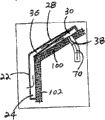
At first, a solar heat collector that the constructure ventilation air is carried out preheating is described according to one embodiment of present invention with reference to Fig. 1-Fig. 3, and with numeral 20 indication synoptically.Device 20 first day light absorption collector plates 22 that comprise on the building.Plate 22 is exposed in the surrounding air, has defined first air collection space 24 between itself and the building.First day light absorption collector plate 22 has a plurality of fresh air inlets 26, and surrounding air can enter first air collection space 24 by fresh air inlet 26.Second day light absorption collector plate 28 is installed on the building, and is adjacent with first day light absorption collector plate 22, defined second air collection space 30 between itself and the building.Second day light absorption collector plate 28 has a plurality of fresh air inlets 32, and air can enter second air collection space 30 by fresh air inlet 32.Second day light absorption collector plate 28 is covered by a glass 34, has defined the middle air flow chamber 36 between itself and second day light absorption collector plate 28.Middle air flow chamber 36 communicates with first air collection space 24 and accepts from the air there.The fresh air inlet 32 of second day light absorption collector plate 28 provides the passage between middle air flow chamber 36 and second air collection space 30.An air outlet 38 extends to interior of building from second air collection space 30.The fan 40 that links to each other with air outlet 38 is delivered to interior of building to air from second air collection space 30 by air outlet 38.
Can the embodiment of solar heat collector 20 be described further with reference to each figure.Specifically as Figure 1-3, device 20 is fixed to the outer surface of building roofing 100.As depicted in figs. 1 and 2, first and second days light absorption collector plate 22 and 28 (abbreviating first and second collector plates 22 and 28 in this article as) is fixed to the outer surface of roofing 100.Roofing 100 at an angle, first position of collector plate 22 on roofing 100 is lower than the position of second collector plate 28.
First and second collector plates 22 and 28 by one comprise metal edge frame 44 and vertically the metal framework structure 42 of inner support bar 46 be fixed to the outer surface of building roofing 100.In the present embodiment, 46 of vertical supporting bars comprise metal framework structure 42 parts of first collector plate 22 and comprise that metal framework structure 42 parts of second collector plate 28 separate.The metal framework structure 42 that comprises metal edge frame 44 and vertical supporting bar 46 is fixed to building roofing 100 with suitable securing member.
First collector plate is fixed in the metal framework structure 42 by the track of metal edge frame 44 and the track of vertical supporting bar 46 1 sides.Notice that first block of plate 22 comprises a plurality of trapezoidal wave cards, defined many accessory plate 22A, 22B similar, overlap joint, 22C... or the like.Each piece accessory plate or trapezoidal wave card 22A, 22B, 22C... include a flat top end 52, pair of angled sidewall 54 and straight substantially cell wall 56.Each sloped sidewall 54 from the upper end 52 a corresponding side extend, each cell wall 56 extends from corresponding sidewall 54.
Shown in Figure 1A, first collector plate 22 comprised the fresh air inlet 26 that spreads all over flat top end 52, sloped sidewall 54 and cell wall 56.Fresh air inlet 26 provides path for surrounding air enters first air collection space 24 from the building outside.In the present embodiment, fresh air inlet 26 is distributed in undulatory first collector plate 22 basically equably, and they are to be formed by the rotation hole in first collector plate 22, and the slit of hole end promptly constitutes fresh air inlet 26.Fresh air inlet 26 apertures are less, help to filter the air of preparing to enter solar heat collector 20.
The outer side covers of first collector plate a kind of selective coating.This selective coating is a kind of solar radiative absorption coating, is beneficial to the absorption solar radiation, and at sunny weather, the infrared heat radiation that collector plate takes place is at various temperatures distributed less, always keeps lower total energy loss.
The same with first collector plate 22, second collector plate 28 also is fixed in the metal framework structure 42 by the track of metal edge frame 44 and the track of vertical supporting bar 46 1 sides.Equally, second collector plate 28 comprises a plurality of trapezoidal wave cards, defined many accessory plate 28A, 28B similar, overlap joint, 28C... or the like.Each piece trapezoidal wave card (accessory plate) includes a straight substantially upper end 58, pair of angled sidewall 60 and straight substantially cell wall 62.Each sloped sidewall 60 from the upper end 58 a corresponding side extend, each cell wall 62 extends from corresponding sidewall 60.
Yet different with first collector plate 22 is that second collector plate 28 is fixedly secured in the metal framework structure 42, each upper end 58 and liner plate 50 and roofing 100 and not parallel.Each upper end 58 and liner plate 50 are at an angle, thereby with roofing 100 also at an angle, thereby make edge 64 near second collector plate 28 of first collector plate 22 adjacent with liner plate (side of track is between the surface of the edge 64 of second collector plate 28 and roofing 100), and away from reserving at interval between the edge 66 of second collector plate 28 of first collector plate 22 and the liner plate 50.Clearly, the distance between second collector plate 28 and the liner plate 50 is along with increasing with the distance of first collector plate 22.Thus, the degree of depth of second air collection space 30 is also along with increasing with the distance of first collector plate 22.
The same with first collector plate 22, second collector plate 28 comprises the second group of fresh air inlet 32 that spreads all over the straight substantially upper end of corrugated plating 58, sloped sidewall 60 and cell wall 62, shown in Figure 1B.Fresh air inlet 32 provides path for second air collection space 30.Yet in the case, second group of fresh air inlet 32 provides path for the air that enters second air collection space 30 from middle air flow chamber 36, preparation.Clearly, further discussion will be done hereinafter in middle air flow chamber 36 between first air collection space 24 and second air collection space 30.In the present embodiment, fresh air inlet 32 is distributed in second collector plate 28 basically equably, is formed by the rotation hole in second collector plate 28, and the slit of hole end promptly constitutes fresh air inlet 32.
The outer side covers of second collector plate and is beneficial to the solar radiative absorption selective coating that absorbs solar radiation, and at sunny weather, the infrared heat radiation that collector plate takes place is at various temperatures distributed less.
Glass with glass plate 34 forms is positioned at second collector plate 28 top.Glass plate 34 is fixed to the first half and the vertical supporting bar 46 of metal edge frame 44 with the bezel 68 that is fixed to metal edge frame 44 the first half and vertical supporting bar 46 surfaces.There is no need glass plate 34 to be packaged on metal edge frame 44 and vertical supporting bar 46 in airtight mode.Only need closely cooperate gets final product, and allows to exist tiny space.
Be spaced apart middle air flow mentioned above chamber 36 between glass plate 34 and second collector plate 28.Middle air flow chamber 36 communicates with first air collection space 24 and second air collection space 30.Air enters middle air flow chamber 36 from first air collection space 24, and leaves middle air flow chamber 36 and enter second air collection space 30.Clearly, the size of vertical supporting bar 46, shape and position are in order to support first and second collector plates 22 and 28, and the edge of the bezel 68 at support glass plate 34 places, allow air to enter middle air flow chamber 36 simultaneously from first air collection space 24.In the present embodiment, this air-flow is to be provided by the air that passes the track slit in the vertical supporting bar 46.
Airduct extends in the building, and the outdoor air of process heating is provided for interior of building by the ventilating opening in the airduct 70.
Fan housing 72 links to each other with airduct 70, and it comprises the fan 40 that air is delivered to interior of building from second air collection space 30.Electronic deep bead in the fan housing 72 can be regulated, and the air of interior of building is mixed with hot blast from second air collection space 30.The size design of the fan 40 in the fan housing is intended to satisfy air-conditioning requirement and prevents to produce in the building negative pressure.By obtaining positive air pressure introducing building by airduct 70 through the outdoor air of heating.Inner air leaves building by ventilating opening and slit.In the present embodiment, fan 40 be one by controller control, the variable speed fan relevant with EAT.Therefore, when air intake is lower than room temperature, fan 40 low-speed runnings.When air intake was higher than room temperature, fan speed improved, and vent air not only is provided, and the space heating also is provided.
In actual use, solar heat collector 20 is positioned on the roofing 100 of building outside.Surrounding air enters first air collection space 24 by the fresh air inlet 26 in first collector plate 22, is tentatively heated at this air.Therefore, the effect of first collector plate 22 is solar thermal collectors of a non-glass.
Next, air passes first air collection space 24 and enters middle air flow chamber 36, and enters second air collection space 30 by the fresh air inlet 32 in second collector plate 28.Air is further heated when passing middle air flow chamber 36 and second air collection space 30.Clearly, the effect of second collector plate 28 is solar thermal collectors of a glass.
At last, air is entered building by fan 40 from 30 extractions of second air collection space and by airduct 70, and the vent air of process heating is provided for building.
With reference to Fig. 4 and Fig. 5, solar heat collector 20 is described according to another embodiment of the present invention.Similar with described first embodiment, the solar heat collector 20 of present embodiment comprises first day light absorption collector plate 22 and second day light absorption collector plate 28.First and second days light absorption collector plate 22 and 28 is similar to above-described first and second days light absorption collector plate, therefore at this to first and second collector plates 22 and 28 needless to say.Equally, similar with described first embodiment, glass plate 34 is positioned at the top of second collector plate 28.Glass plate 34 is similar to above-described glass plate, therefore at this needless to say.Yet different with described first embodiment is that in the present embodiment, first collector plate 22 is positioned at the metope 102 of building.Second collector plate 28 is positioned on the building roofing 100, rather than is positioned at same metope.Therefore, metal framework structure 42 has an elbow in midpoint, and vertical supporting bar 46 promptly is positioned at herein and along the metope 102 of building and the intersecting lens of roofing 100.The remainder of solar heat collector 20 comprises that air flows, and all similar with above-described solar heat collector 20, therefore there is no need to go into details.
With reference to Fig. 6, solar heat collector 20 is described according to still another embodiment of the invention.As shown in the figure, be different from 22, the first collector plates 22 of undulatory first collector plate and form by the small-sized accessory plate of many overlap joints, each accessory plate all with the surface of roofing 100 at an angle.The most approaching position of distance is the top of accessory plate between each accessory plate and the building roofing 100.Therefore, the distance between accessory plate and the roofing surface increases from top to bottom.Be different from the fresh air inlet 26 that spreads all over corrugated plating, fresh air inlet 26 is positioned at accessory plate bottom, and the distance between the surface of accessory plate and roofing 100 is maximum herein.Although shown in the figure be first collector plate 22, second collector plate 28 that accessory plate can be used to equally is above-described, have glass 34.
With reference to Fig. 7, shown is another embodiment of the present invention.In the present embodiment, solar heat collector 20 is similar to solar heat collector above-described, shown in Figure 6 20.Yet in the present embodiment, solar heat collector 20 is installed in the metope 102 of building, but not roofing.
So far, from a plurality of examples this explanation is described.Modifications and changes can take place in above-described embodiment.For example, the density of the fresh air inlet in equally distributed fresh air inlet 26, the first day light absorption collector plate can be along with increasing with the distance of second day light absorption collector plate in first day light absorption collector plate although described first embodiment touches upon.Similarly, the density of the fresh air inlet 32 in second day light absorption collector plate can be along with increasing with the distance of air outlet.In addition, the size of the fresh air inlet in first day light absorption collector plate can be along with increasing with the distance of second day light absorption collector plate.Similarly, the size of the fresh air inlet in second day light absorption collector plate can be along with increasing with the distance of air outlet.
Other alternative also is possible.For example, in above-described embodiment, is furnished with built-in track in the vertical supporting bar 46.In alternative, track is fixed to vertical supporting bar 46.In this case, be that many short tracks are attached to vertical supporting bar 46, between them, reserve at interval so that the air communication mistake.Similarly, track can be fixed to metal edge frame 44, but not is built in metal edge frame 44.In addition, although fresh air inlet 26 as described above and fresh air inlet 32 are formed by the rotation hole in first and second collector plates 22 and 28 respectively, in alternative, 32 of fresh air inlet 26 and fresh air inlets are formed by the punching hole in first and second collector plates 22 and 28 respectively.
In another version, first and second collector plates can be positioned on the same metope of building, but not are positioned at roof of buildings or lay respectively at roofing and metope.Be vertical plane with the collector plate of ripple is intimate this moment, as shown in Figure 1.
By to the digesting of this skill, also have other modifications or version to embodiment described herein.All these type of modifications and variations forms all are regarded as category of the present invention.
Claims (34)
1, a kind of device for preheating ventilation air that is used for building comprises:
First day light absorption collector plate, be installed on the described building, this collector plate is exposed in the surrounding air, defined first air collection space between itself and the described building, first day light absorption collector plate has a plurality of fresh air inlets, and surrounding air can enter first air collection space by fresh air inlet;
Second day light absorption collector plate, be installed on the described building, adjacent with described first day light absorption collector plate, second day light absorption collector plate has defined second air collection space between itself and the described building, second day light absorption collector plate has a plurality of fresh air inlets, and surrounding air can enter second air collection space by fresh air inlet;
A glass, cover on described second day light absorption collector plate, defined the middle air flow chamber between itself and second day light absorption collector plate, described middle air flow chamber communicates with described first air collection space and accepts from the air, and the described fresh air inlet in described second day light absorption collector plate provides the path between described middle air flow chamber and described second air collection space there;
An air outlet enters described building from described second air collection space, is used for ventilating;
A fan communicates with described air outlet, is used for air is delivered to described interior of building from described second air collection space by described air outlet.
2, device according to claim 1 is characterized in that, described first day light absorption collector plate is a corrugated plating.
3, device according to claim 2 is characterized in that, the fresh air inlet of described first day light absorption collector plate is made of at least one hole in first day light absorption collector plate and at least one seam.
4, device according to claim 1 is characterized in that, described second day light absorption collector plate is a corrugated plating.
5, device according to claim 4 is characterized in that, the fresh air inlet of described second day light absorption collector plate is made of at least one hole in described second day light absorption collector plate and at least one seam.
6, device according to claim 1 is characterized in that, described first and second days light absorption collector plate is on the first surface of described building.
7, device according to claim 1, it is characterized in that, described first day light absorption collector plate is on the first surface of described building, and described second day light absorption collector plate is on the second surface of described building, and is adjacent with described first surface.
8, device according to claim 1 is characterized in that, the described fresh air inlet in described first day light absorption collector plate is evenly distributed on described first day light absorption collector plate.
9, device according to claim 1 is characterized in that, the outside of described first day light absorption collector plate has face coat, can promote the absorption and the reduction far-infrared heat radiation of solar radiation are distributed.
10, device according to claim 1 is characterized in that, described second day light absorption collector plate outside has face coat, can promote the absorption and the reduction far-infrared heat radiation of solar radiation are distributed.
11, device according to claim 1 is characterized in that, second day light absorption collector plate is positioned at the top of described first day light absorption collector plate.
12, device according to claim 1 is characterized in that, described first day light absorption collector plate is positioned on the vertical surface of described building.
13, device according to claim 12 is characterized in that, described second day light absorption collector plate is positioned on the described vertical surface of described building.
14, device according to claim 12 is characterized in that, described second day light absorption collector plate is positioned on the described roof of buildings.
15, device according to claim 12 is characterized in that, described first day light absorption collector plate is a corrugated plating, is the vertical plane setting.
16, device according to claim 1 is characterized in that, first day light absorption collector plate is made up of the accessory plate of a plurality of overlap joints.
17, device according to claim 1 is characterized in that, second day light absorption collector plate is made up of the accessory plate of a plurality of overlap joints.
18, a kind of vent air heating means that are used for building comprise:
First day light absorption collector plate is installed on described building, this collector plate is exposed in the surrounding air, defined first air collection space between itself and the described building, first day light absorption collector plate has a plurality of fresh air inlets, and surrounding air can enter first air collection space by fresh air inlet;
Second day light absorption collector plate is installed on described building, second day light absorption collector plate has defined second air collection space between itself and the described building, second day light absorption collector plate has a plurality of fresh air inlets, and surrounding air can enter second air collection space by fresh air inlet;
On described second day light absorption collector plate, cover a glass, glass has defined the middle air flow chamber between itself and second day light absorption collector plate, described middle air flow chamber communicates with described first air collection space and accepts from the air, and the described fresh air inlet in described second day light absorption collector plate provides the path between described middle air flow chamber and described second air collection space there;
With heat from first day light absorption collector plate, the outdoor air in first air collection space of preheating, and preheated air sent into the middle air flow chamber;
By sending into second air collection space from the preheated air of middle air flow chamber, heat the preheated air in second air collection space, hot blast is provided;
Air outlet by described second air collection space extracts described hot blast and described hot blast is entered described building.
19, method according to claim 18 is characterized in that, described first day light absorption collector plate is installed on described building is comprised that installation first day light absorption collector plate and described first day light absorption collector plate are corrugated plating.
20, method according to claim 18, it is characterized in that, described first day light absorption collector plate is installed on described building is comprised that the fresh air inlet that first day light absorption collector plate and described a plurality of first day light absorption collector plates are installed is made of at least one hole and at least one seam.
21, method according to claim 18 is characterized in that, described second day light absorption collector plate is installed on described building is comprised that installation second day light absorption collector plate and described second day light absorption collector plate are corrugated plating.
22, method according to claim 21, it is characterized in that, described second day light absorption collector plate is installed on described building is comprised that the fresh air inlet that second day light absorption collector plate and described a plurality of first day light absorption collector plates are installed is made of at least one hole and at least one seam.
23, method according to claim 18 is characterized in that, described first and second days light absorption collector plate is installed on the first surface of described building.
24, method according to claim 18, it is characterized in that, described first day light absorption collector plate is installed on the first surface of described building, and described second day light absorption collector plate is installed on the second surface of described building, and is adjacent with described first surface.
25, method according to claim 18, it is characterized in that, comprise that at described first day light absorption collector plate of installation on the described building fresh air inlet that first day light absorption collector plate and described first day light absorption collector plate are installed is evenly distributed on described first day light absorption collector plate.
26, method according to claim 18 is characterized in that, the preheating chamber outer air comprises from the whole surface radiating of described first day light absorption collector plate.
27, method according to claim 18 is characterized in that, the heating preheated air comprises from the whole surface radiating of described second day light absorption collector plate.
28, method according to claim 18, it is characterized in that, the outside that described first day light absorption collector plate of installation is included in described first day light absorption collector plate on described building provides face coat, and this face coat can promote the absorption of solar radiation and reduce far-infrared heat radiation and distribute.
29, method according to claim 18, it is characterized in that, the outside that described second day light absorption collector plate of installation is included in described second day light absorption collector plate on described building provides face coat, and this face coat can promote the absorption of solar radiation and reduce far-infrared heat radiation and distribute.
30. method according to claim 18 is characterized in that, described second day light absorption collector plate is installed is comprised the top of described second day light absorption collector plate being installed and being positioned at described first day light absorption collector plate.
31, method according to claim 18 is characterized in that, described first day light absorption collector plate is installed is comprised a plurality of accessory plates that described first day light absorption collector plate of formation is installed.
32, method according to claim 18 is characterized in that, described second day light absorption collector plate is installed is comprised a plurality of accessory plates that formation second day light absorption collector plate is installed.
33, one is used, is used for the device that the preheating vent air of building is carried with fan, and this device comprises:
First day light absorption collector plate, be installed on the described building, this collector plate is exposed in the surrounding air, defined first air collection space between itself and the described building, first day light absorption collector plate has a plurality of fresh air inlets, and surrounding air can enter first air collection space by fresh air inlet;
Second day light absorption collector plate, be installed on the described building, adjacent with described first day light absorption collector plate, second day light absorption collector plate has defined second air collection space between itself and the described building, second day light absorption collector plate has a plurality of fresh air inlets, and surrounding air can enter second air collection space by fresh air inlet;
A glass, cover on described second day light absorption collector plate, defined the middle air flow chamber between itself and second day light absorption collector plate, described middle air flow chamber communicates with described first air collection space and accepts from the air, and the described fresh air inlet in described second day light absorption collector plate provides the path between described middle air flow chamber and described second air collection space there;
An air outlet, fan are extracted preheated air out and are blown to described building by the air outlet of described second air collection space.
34, device according to claim 33 is characterized in that, the speed of fan is variable, can control according to the air themperature that extracts from air outlet.
Applications Claiming Priority (2)
| Application Number | Priority Date | Filing Date | Title |
|---|---|---|---|
| US10/846,112 US7032588B2 (en) | 2004-05-14 | 2004-05-14 | Method and apparatus for preheating ventilation air for a building |
| US10/846112 | 2004-05-14 |
Publications (2)
| Publication Number | Publication Date |
|---|---|
| CN1760601A CN1760601A (en) | 2006-04-19 |
| CN100572974C true CN100572974C (en) | 2009-12-23 |
Family
ID=34941265
Family Applications (1)
| Application Number | Title | Priority Date | Filing Date |
|---|---|---|---|
| CNB2005100725420A Active CN100572974C (en) | 2004-05-14 | 2005-05-11 | The device for preheating ventilation air of building and method |
Country Status (11)
| Country | Link |
|---|---|
| US (1) | US7032588B2 (en) |
| EP (1) | EP1596138B1 (en) |
| JP (1) | JP4676808B2 (en) |
| CN (1) | CN100572974C (en) |
| AT (1) | ATE483944T1 (en) |
| CA (1) | CA2503395C (en) |
| DE (1) | DE602005023935D1 (en) |
| DK (1) | DK1596138T3 (en) |
| ES (1) | ES2356183T3 (en) |
| PL (1) | PL1596138T3 (en) |
| PT (1) | PT1596138E (en) |
Cited By (2)
| Publication number | Priority date | Publication date | Assignee | Title |
|---|---|---|---|---|
| CN102226586A (en) * | 2011-04-20 | 2011-10-26 | 上海福奥建筑科技有限公司 | Solar flat type heat collector and heat collection plate thereof |
| CN104838217B (en) * | 2012-10-02 | 2018-05-15 | G·库尔特 | Solar air warm up/down system |
Families Citing this family (25)
| Publication number | Priority date | Publication date | Assignee | Title |
|---|---|---|---|---|
| DE102005058887A1 (en) * | 2005-12-09 | 2007-06-14 | Stys, Antoni Slawomir, Dipl.-Ing. | Solar heating system for building with blown airflow to heat rooms or warm water supply |
| US9574783B2 (en) | 2006-05-18 | 2017-02-21 | Hollick Solar Systems Limited | Method and apparatus for two stage cooling of ambient air |
| US8827779B2 (en) * | 2006-05-18 | 2014-09-09 | Hollick Solar Systems Limited | Method and apparatus for cooling ventilation air for a building |
| CA2559641C (en) * | 2006-09-13 | 2014-04-15 | Matrix Energy Inc. | Solar air heating system |
| US7677243B2 (en) | 2007-01-22 | 2010-03-16 | Wal-Mart Stores, Inc. | Solar heating system and architectural structure with a solar heating system |
| US20100186734A1 (en) * | 2007-02-05 | 2010-07-29 | Paul Riis Arndt | Solar air heater for heating air flow |
| IE86172B1 (en) | 2007-05-01 | 2013-04-10 | Kingspan Res & Dev Ltd | A composite insulating panel having a heat exchange conduit means |
| CA2638257C (en) * | 2007-07-26 | 2013-04-09 | Enerconcept Technologies Inc. | Perforated transparent glazing for heat recovery and solar air heating |
| SE533796C2 (en) * | 2008-02-07 | 2011-01-18 | Soltech Energy Sweden Ab | Solar energy system comprising a space in the roof of a building |
| WO2009125159A2 (en) * | 2008-04-01 | 2009-10-15 | OPALY, Société par actions simplifiée | Method and device for trimming for facade or roof of a building |
| FR2929379A1 (en) * | 2008-04-01 | 2009-10-02 | Opaly Soc Par Actions Simplifi | Hollow panel for fabricating wall of building, has fluid circulation channel extending between receiver and perforated receiver that is exposed to heat radiation and transform radiation by reflection, transmission and/or absorption |
| EP2315980A4 (en) * | 2008-07-29 | 2015-05-06 | Syenergy Integrated Energy Solutions Inc | Curved transpired solar air heater and conduit |
| JP2010096457A (en) * | 2008-10-17 | 2010-04-30 | Nippon Light Metal Co Ltd | Air conditioning device |
| TR200900233A1 (en) * | 2009-01-13 | 2010-08-23 | Gökser Mak.San.Ve Ti̇c.Ltd.Şti̇. | Hybrid food drying system |
| NL1036649C2 (en) * | 2009-03-02 | 2010-09-03 | Luijten Smeulders Architecten B V | BUILDING WITH ENERGY PRODUCTION PRODUCTS. |
| US8371073B2 (en) * | 2010-03-04 | 2013-02-12 | Michael Fuller Architects, Pc | Building with integrated natural systems |
| US8555872B2 (en) | 2011-03-04 | 2013-10-15 | John Allan Dolphin | Solar heater |
| US20130118478A1 (en) * | 2011-11-11 | 2013-05-16 | Masdar Institute Of Science And Technology | Liquid-air transpired solar collectors |
| US9664396B2 (en) * | 2012-11-08 | 2017-05-30 | Iis Institute For Independent Studies Gmbh | Building envelope and method for adjusting the temperature in a building |
| NL2011550C2 (en) * | 2013-10-03 | 2015-04-07 | Unda Maris Holding N V | WALL SYSTEM, FACADE PANEL THEREFORE, AND THE BUILDING PROVIDED FOR THIS. |
| GB2526269B (en) * | 2014-05-16 | 2018-09-12 | Solar Frame Solutions Ltd | Solar-collector roofing assembly |
| GB2540384B (en) * | 2015-07-15 | 2020-04-29 | Energy Transitions Ltd | Transpired solar collector |
| CN105865042B (en) * | 2016-06-08 | 2017-12-05 | 日出东方太阳能股份有限公司 | A kind of solar air heater and heating means |
| CN110500774B (en) * | 2019-08-22 | 2021-06-04 | 沂源县源能热力有限公司 | Heating system with regulatory function |
| PL3988859T3 (en) | 2020-10-26 | 2023-05-15 | Almeco Gmbh | Deformable composite material for uncovered solar energy absorbent collector panels with low infrared radiation losses |
Family Cites Families (18)
| Publication number | Priority date | Publication date | Assignee | Title |
|---|---|---|---|---|
| JPS499492B1 (en) * | 1970-12-22 | 1974-03-05 | ||
| US4143815A (en) * | 1975-10-22 | 1979-03-13 | Energietechnik Gmbh | Heating apparatus |
| US4090494A (en) * | 1977-01-24 | 1978-05-23 | Southern Illinois University Foundation | Solar collector |
| US4478210A (en) * | 1979-04-16 | 1984-10-23 | Sieradski Leonard M | Solar heating system |
| FR2469674A1 (en) * | 1979-11-15 | 1981-05-22 | Omnium Fs Indl Cal | Solar energy trap with absorbent bodies of corrugated bitumastic board - to smooth variations in the rate of energy capture |
| FR2491599B1 (en) * | 1980-10-08 | 1986-04-04 | Olivier Gilbert | SOLAR COLLECTOR USING AIR AS A HEAT FLUID, AND ITS COMPONENTS |
| NL8102154A (en) * | 1981-05-01 | 1982-12-01 | Drs Hendrik Jan Dorrestijn | Roof mounted solar heat collector - has surface of flat porous highly light absorbent material |
| CA1196825A (en) | 1982-05-04 | 1985-11-19 | John C. Hollick | Method for preheating ventilation air in a building |
| FR2535444A1 (en) * | 1982-10-29 | 1984-05-04 | Dalmas Ets | Solar collector using air. |
| CA1283333C (en) | 1988-02-11 | 1991-04-23 | John Carl Hollick | Method and apparatus for preheating ventilation air for a building |
| US4899728A (en) | 1989-01-27 | 1990-02-13 | Solarwall International Limited | Method and apparatus for preheating ventilation air for a building |
| JPH04136660A (en) * | 1990-09-26 | 1992-05-11 | Yoshitomi Takeda | Solar system |
| JPH0781747B2 (en) * | 1993-03-31 | 1995-09-06 | 元旦ビューティ工業株式会社 | Solar heat collector |
| US5596981A (en) * | 1993-07-19 | 1997-01-28 | Soucy; Paul B. | Solar device and method for assembly |
| DE19505918A1 (en) * | 1995-02-21 | 1996-08-22 | Karlfried Cost | Solar collector for heating air |
| US5692491A (en) * | 1996-04-19 | 1997-12-02 | Midwest Research Institute | Unglazed transpired solar collector having a low thermal-conductance absorber |
| CA2230471C (en) | 1998-02-25 | 2001-09-11 | John Carl Hollick | Combined solar collector and photovoltaic cells |
| US5935343A (en) | 1998-03-13 | 1999-08-10 | Hollick; John Carl | Combined solar collector and photovoltaic cells |
-
2004
- 2004-05-14 US US10/846,112 patent/US7032588B2/en active Active
-
2005
- 2005-04-01 CA CA002503395A patent/CA2503395C/en active Active
- 2005-04-21 JP JP2005124287A patent/JP4676808B2/en not_active Expired - Fee Related
- 2005-05-11 CN CNB2005100725420A patent/CN100572974C/en active Active
- 2005-05-12 AT AT05252918T patent/ATE483944T1/en not_active IP Right Cessation
- 2005-05-12 EP EP05252918A patent/EP1596138B1/en active Active
- 2005-05-12 DE DE602005023935T patent/DE602005023935D1/en active Active
- 2005-05-12 ES ES05252918T patent/ES2356183T3/en active Active
- 2005-05-12 PT PT05252918T patent/PT1596138E/en unknown
- 2005-05-12 PL PL05252918T patent/PL1596138T3/en unknown
- 2005-05-12 DK DK05252918.7T patent/DK1596138T3/en active
Cited By (2)
| Publication number | Priority date | Publication date | Assignee | Title |
|---|---|---|---|---|
| CN102226586A (en) * | 2011-04-20 | 2011-10-26 | 上海福奥建筑科技有限公司 | Solar flat type heat collector and heat collection plate thereof |
| CN104838217B (en) * | 2012-10-02 | 2018-05-15 | G·库尔特 | Solar air warm up/down system |
Also Published As
| Publication number | Publication date |
|---|---|
| US7032588B2 (en) | 2006-04-25 |
| CN1760601A (en) | 2006-04-19 |
| EP1596138B1 (en) | 2010-10-06 |
| PT1596138E (en) | 2011-01-14 |
| EP1596138A2 (en) | 2005-11-16 |
| CA2503395C (en) | 2007-01-09 |
| US20050252507A1 (en) | 2005-11-17 |
| ATE483944T1 (en) | 2010-10-15 |
| DK1596138T3 (en) | 2011-01-31 |
| DE602005023935D1 (en) | 2010-11-18 |
| ES2356183T3 (en) | 2011-04-05 |
| EP1596138A3 (en) | 2007-05-23 |
| JP4676808B2 (en) | 2011-04-27 |
| PL1596138T3 (en) | 2011-03-31 |
| CA2503395A1 (en) | 2005-11-14 |
| JP2005326142A (en) | 2005-11-24 |
Similar Documents
| Publication | Publication Date | Title |
|---|---|---|
| CN100572974C (en) | The device for preheating ventilation air of building and method | |
| CN104838217B (en) | Solar air warm up/down system | |
| CN102168882B (en) | Method and apparatus for cooling ventilation air for building | |
| EP0380349B1 (en) | Improved method and apparatus for preheating ventilation air for a building | |
| KR101782433B1 (en) | Air-conditioning System Using Air Type Photohvoltaic-thermal Preheating Module | |
| US8276580B2 (en) | Modular transpired solar air collector | |
| JP2675385B2 (en) | Method and apparatus for preheating ventilation air | |
| CN106989463A (en) | Air through tunnel and the energy storage ventilated hybrid system of solar chimney | |
| CN105020770B (en) | A kind of new type solar energy thermal storage heating system and device and method | |
| JP4171014B2 (en) | Pneumatic collector and pneumatic solar collector ventilation system | |
| CN101059279B (en) | Air type solar energy heat-collecting ventilation system | |
| KR101998222B1 (en) | Heating block by intercepting sunlight, and heating wall system comprising heating block | |
| JPH0547754U (en) | Hot air device using solar heat | |
| US20120312293A1 (en) | Perforated transparent glazing for heat recovery and solar air heating | |
| CA2780423C (en) | Perforated transparent glazing for heat recovery and solar air heating | |
| JP4541372B2 (en) | Pneumatic solar collector ventilation system | |
| JP2846913B2 (en) | Building air preheating method and apparatus | |
| CN109386973A (en) | Roll over the new air -return duct partition type solar energy air heat collector of shape spoiler and heating system | |
| CN202092334U (en) | Flat plate solar collector and heat-collection plate thereof | |
| CN207162752U (en) | It is adapted to rural area coal to change the fan coil units that electricity uses | |
| CN206875638U (en) | Air through tunnel and the energy storage ventilated hybrid system of solar chimney | |
| JPS58214745A (en) | Room heating apparatus utilizing solar heat | |
| JP4152538B2 (en) | Solar heating system | |
| JPS5911818B2 (en) | Improvements to the solar wall | |
| CN102226586A (en) | Solar flat type heat collector and heat collection plate thereof |
Legal Events
| Date | Code | Title | Description |
|---|---|---|---|
| C06 | Publication | ||
| PB01 | Publication | ||
| C10 | Entry into substantive examination | ||
| SE01 | Entry into force of request for substantive examination | ||
| C14 | Grant of patent or utility model | ||
| GR01 | Patent grant |