EP0440103A2 - Roofing tile or roofing stone with solar plate - Google Patents
Roofing tile or roofing stone with solar plate Download PDFInfo
- Publication number
- EP0440103A2 EP0440103A2 EP91100962A EP91100962A EP0440103A2 EP 0440103 A2 EP0440103 A2 EP 0440103A2 EP 91100962 A EP91100962 A EP 91100962A EP 91100962 A EP91100962 A EP 91100962A EP 0440103 A2 EP0440103 A2 EP 0440103A2
- Authority
- EP
- European Patent Office
- Prior art keywords
- roof tile
- solar panel
- roof
- solar
- tile
- Prior art date
- Legal status (The legal status is an assumption and is not a legal conclusion. Google has not performed a legal analysis and makes no representation as to the accuracy of the status listed.)
- Withdrawn
Links
- 239000004575 stone Substances 0.000 title abstract description 17
- 239000000463 material Substances 0.000 claims abstract description 5
- 239000004033 plastic Substances 0.000 claims abstract description 5
- 239000000919 ceramic Substances 0.000 claims abstract description 4
- 239000004927 clay Substances 0.000 claims abstract description 4
- 239000004567 concrete Substances 0.000 claims abstract description 4
- 239000011324 bead Substances 0.000 claims description 4
- 239000011449 brick Substances 0.000 description 12
- 238000010276 construction Methods 0.000 description 7
- 238000005516 engineering process Methods 0.000 description 7
- 230000007774 longterm Effects 0.000 description 5
- 238000004519 manufacturing process Methods 0.000 description 4
- 230000003287 optical effect Effects 0.000 description 4
- 239000011521 glass Substances 0.000 description 3
- 210000002105 tongue Anatomy 0.000 description 3
- BQCADISMDOOEFD-UHFFFAOYSA-N Silver Chemical compound [Ag] BQCADISMDOOEFD-UHFFFAOYSA-N 0.000 description 2
- 239000011248 coating agent Substances 0.000 description 2
- 238000000576 coating method Methods 0.000 description 2
- 238000001816 cooling Methods 0.000 description 2
- 238000009434 installation Methods 0.000 description 2
- 230000010354 integration Effects 0.000 description 2
- 238000000034 method Methods 0.000 description 2
- 238000010248 power generation Methods 0.000 description 2
- 229910052709 silver Inorganic materials 0.000 description 2
- 239000004332 silver Substances 0.000 description 2
- 230000032683 aging Effects 0.000 description 1
- 230000033228 biological regulation Effects 0.000 description 1
- 238000004040 coloring Methods 0.000 description 1
- 230000007797 corrosion Effects 0.000 description 1
- 238000005260 corrosion Methods 0.000 description 1
- 230000002950 deficient Effects 0.000 description 1
- 238000005538 encapsulation Methods 0.000 description 1
- 238000007667 floating Methods 0.000 description 1
- 230000000855 fungicidal effect Effects 0.000 description 1
- 230000017525 heat dissipation Effects 0.000 description 1
- 230000002363 herbicidal effect Effects 0.000 description 1
- 229910052751 metal Inorganic materials 0.000 description 1
- 239000002184 metal Substances 0.000 description 1
- 238000013082 photovoltaic technology Methods 0.000 description 1
- 239000002985 plastic film Substances 0.000 description 1
- 229920006255 plastic film Polymers 0.000 description 1
- 238000003825 pressing Methods 0.000 description 1
- 230000002040 relaxant effect Effects 0.000 description 1
- 239000005871 repellent Substances 0.000 description 1
- 238000007789 sealing Methods 0.000 description 1
- 238000005476 soldering Methods 0.000 description 1
- 239000000126 substance Substances 0.000 description 1
- 238000009423 ventilation Methods 0.000 description 1
- 230000000007 visual effect Effects 0.000 description 1
Images


Classifications
-
- H—ELECTRICITY
- H02—GENERATION; CONVERSION OR DISTRIBUTION OF ELECTRIC POWER
- H02S—GENERATION OF ELECTRIC POWER BY CONVERSION OF INFRARED RADIATION, VISIBLE LIGHT OR ULTRAVIOLET LIGHT, e.g. USING PHOTOVOLTAIC [PV] MODULES
- H02S20/00—Supporting structures for PV modules
- H02S20/20—Supporting structures directly fixed to an immovable object
- H02S20/22—Supporting structures directly fixed to an immovable object specially adapted for buildings
- H02S20/23—Supporting structures directly fixed to an immovable object specially adapted for buildings specially adapted for roof structures
- H02S20/25—Roof tile elements
-
- F—MECHANICAL ENGINEERING; LIGHTING; HEATING; WEAPONS; BLASTING
- F24—HEATING; RANGES; VENTILATING
- F24S—SOLAR HEAT COLLECTORS; SOLAR HEAT SYSTEMS
- F24S20/00—Solar heat collectors specially adapted for particular uses or environments
- F24S20/60—Solar heat collectors integrated in fixed constructions, e.g. in buildings
- F24S20/69—Solar heat collectors integrated in fixed constructions, e.g. in buildings in the form of shingles or tiles
-
- Y—GENERAL TAGGING OF NEW TECHNOLOGICAL DEVELOPMENTS; GENERAL TAGGING OF CROSS-SECTIONAL TECHNOLOGIES SPANNING OVER SEVERAL SECTIONS OF THE IPC; TECHNICAL SUBJECTS COVERED BY FORMER USPC CROSS-REFERENCE ART COLLECTIONS [XRACs] AND DIGESTS
- Y02—TECHNOLOGIES OR APPLICATIONS FOR MITIGATION OR ADAPTATION AGAINST CLIMATE CHANGE
- Y02B—CLIMATE CHANGE MITIGATION TECHNOLOGIES RELATED TO BUILDINGS, e.g. HOUSING, HOUSE APPLIANCES OR RELATED END-USER APPLICATIONS
- Y02B10/00—Integration of renewable energy sources in buildings
- Y02B10/10—Photovoltaic [PV]
-
- Y—GENERAL TAGGING OF NEW TECHNOLOGICAL DEVELOPMENTS; GENERAL TAGGING OF CROSS-SECTIONAL TECHNOLOGIES SPANNING OVER SEVERAL SECTIONS OF THE IPC; TECHNICAL SUBJECTS COVERED BY FORMER USPC CROSS-REFERENCE ART COLLECTIONS [XRACs] AND DIGESTS
- Y02—TECHNOLOGIES OR APPLICATIONS FOR MITIGATION OR ADAPTATION AGAINST CLIMATE CHANGE
- Y02B—CLIMATE CHANGE MITIGATION TECHNOLOGIES RELATED TO BUILDINGS, e.g. HOUSING, HOUSE APPLIANCES OR RELATED END-USER APPLICATIONS
- Y02B10/00—Integration of renewable energy sources in buildings
- Y02B10/20—Solar thermal
-
- Y—GENERAL TAGGING OF NEW TECHNOLOGICAL DEVELOPMENTS; GENERAL TAGGING OF CROSS-SECTIONAL TECHNOLOGIES SPANNING OVER SEVERAL SECTIONS OF THE IPC; TECHNICAL SUBJECTS COVERED BY FORMER USPC CROSS-REFERENCE ART COLLECTIONS [XRACs] AND DIGESTS
- Y02—TECHNOLOGIES OR APPLICATIONS FOR MITIGATION OR ADAPTATION AGAINST CLIMATE CHANGE
- Y02E—REDUCTION OF GREENHOUSE GAS [GHG] EMISSIONS, RELATED TO ENERGY GENERATION, TRANSMISSION OR DISTRIBUTION
- Y02E10/00—Energy generation through renewable energy sources
- Y02E10/40—Solar thermal energy, e.g. solar towers
- Y02E10/44—Heat exchange systems
-
- Y—GENERAL TAGGING OF NEW TECHNOLOGICAL DEVELOPMENTS; GENERAL TAGGING OF CROSS-SECTIONAL TECHNOLOGIES SPANNING OVER SEVERAL SECTIONS OF THE IPC; TECHNICAL SUBJECTS COVERED BY FORMER USPC CROSS-REFERENCE ART COLLECTIONS [XRACs] AND DIGESTS
- Y02—TECHNOLOGIES OR APPLICATIONS FOR MITIGATION OR ADAPTATION AGAINST CLIMATE CHANGE
- Y02E—REDUCTION OF GREENHOUSE GAS [GHG] EMISSIONS, RELATED TO ENERGY GENERATION, TRANSMISSION OR DISTRIBUTION
- Y02E10/00—Energy generation through renewable energy sources
- Y02E10/50—Photovoltaic [PV] energy
-
- Y—GENERAL TAGGING OF NEW TECHNOLOGICAL DEVELOPMENTS; GENERAL TAGGING OF CROSS-SECTIONAL TECHNOLOGIES SPANNING OVER SEVERAL SECTIONS OF THE IPC; TECHNICAL SUBJECTS COVERED BY FORMER USPC CROSS-REFERENCE ART COLLECTIONS [XRACs] AND DIGESTS
- Y10—TECHNICAL SUBJECTS COVERED BY FORMER USPC
- Y10S—TECHNICAL SUBJECTS COVERED BY FORMER USPC CROSS-REFERENCE ART COLLECTIONS [XRACs] AND DIGESTS
- Y10S136/00—Batteries: thermoelectric and photoelectric
- Y10S136/291—Applications
Definitions
- the invention relates to a roof tile / roof tile from a full-surface plate made of clay, ceramic, concrete or plastic as a carrier of a solar panel attached to the top with photovoltaic solar cells.
- PV photovolatic
- Puncturing a conventional roof skin inevitably causes sealing and then Tightness problems.
- the long-term impermeability of an injured, pierced roof skin is not guaranteed by the daily thermal tensions or by the aging movements of the roof and can lead to major damage.
- This fastening technology is also expensive in terms of both the material components and the personnel costs of specially trained specialists.
- the object of the invention is to provide a roof tile or roof tile which, with simple construction, manufacture and installation, enables inexpensive technical and optical integration of the photovoltaic into the architecture.
- the solar panel is positively attached to the top of the roof tile / roof tile in such a way that the material of the roof tile / roof tile protrudes at least on two opposite sides in such a way that it overlaps an area, in particular the edge, of the solar panel, so that the solar panel is secured against lifting upwards.
- fastening methods can be used which allow the roof tile or roof tile to be produced by customary roof tile production processes, and the roof tile can also be used without a module for covering the roof.
- the solar panel overlaps the roof tile / roof tile in such a way that the roof tile / roof tile is covered.
- clips can protrude laterally on the solar panel to reach under the roof tile / roof tile.
- a very simple construction and handling with secure attachment is achieved when the solar panel reaches its attached position by moving it in its plane.
- a particularly simple and secure attachment is achieved if the upper side has a concave recess, on the upper edge of which the solar panel is attached. This also ventilates and cools the solar panel. A cable duct is also formed.
- the upper edge of the concave recess should overlap the edge of the solar panel in whole or in sections. It is also advantageous here if the edge of the solar panel lies in a form-fitting manner in the groove, groove or groove-shaped edge.
- the recess can form the section of a cylinder jacket whose axis lies parallel to the falling line of the roof tile / roof tile.
- the cavity formed by the recess and covered by the solar panel serves as a cable duct and / or as a ventilation duct.
- Good cooling with the simplest form of the channel is achieved if the cavity formed by the recess and covered by the solar panel is open in the upper and lower areas of the roof tile / roof tile.
- the solar panel cannot cover the recess in the upper area. It is also advantageous if there is a slot or a notch in the area of the lower opening in the recess wall for inserting an electrical connection cable.
- a particularly advantageous additional or alternative method of fastening is when the roof tile / roof tile has a plurality of projections, in particular pegs, which lie in correspondingly shaped openings in the solar panel.
- the solar panel can also have a plurality of projections, in particular pegs, which lie in correspondingly shaped openings in the roof tile / roof tile.
- An architectural roof surface divided into sloping lines is achieved if the sloping longitudinal edge of the roof tile / roof tile, which is not covered by the solar panel and the adjacent roof tile / roof tile, is bulged upward in a bulge.
- An optical improvement is achieved if the solar panel has a textured, structured, and / or soft-reflecting surface.
- the solar panel have an anti-stick, dirt-repellent coating. Good optical quality over a long period of time is achieved if the solar panel has a herbicidal, fungicidal and / or antimossan coating. It is also advantageous if the solar panel in the upper area of the roof tile / roof tile is attached so far from the front edge of the overlying tile that this front edge of the overlying tile does not cast a shadow on the solar cells.
- the solar panel does not have a bulge-like, raised, water-blocking border at the rain-draining edge.
- the photovoltaic roof tile / roof tile system consists of two components:
- the basic element is a middle field roof tile or roof tile 1 in the traditional interlocking, interlocking, overlapping construction.
- the front surface 2 of the roof tile / roof tile has a partially cylindrical recess 3.
- the lowered trough 3 or surface forms a channel or a channel, opens towards the front and rises in a rounded manner in the rear part.
- Undercut grooves 4 with horizontal offsets (corrugation) for receiving the two side edges of the frameless photovoltaic module 5 are incorporated in the two longitudinal flanks.
- This roof tile / roof tile is laid conventionally by the local roofer according to traditional craftsmanship and DIN regulations.
- the entire roof of the house is due to the traditional roof tile / roof stone construction driving rain-snow storm-tight. From the overall roof tile system (such as the reform tile) with local aisle, ridge, vent half-tiles, only the middle field tile has been redesigned.
- the entire roof tile / roof tile system is solar cell blue with the same reflection values as the photovoltaic module, thus ensuring the uniformity and visual harmony of the roof.
- An architectural roof surface divided into sloping lines is achieved if the sloping longitudinal edge 1c of the roof tile, which is not covered by the solar panel 5 and the adjacent roof tile / roof tile 1, is bulged upward in a bead shape.
- the second element of the roof tile / roof tile system is the photovoltaic module 5.
- This PV module 5 consists of a thin 1.5 - 2.0 mm thick chemically hardened, iron-free, highly light-transparent glass pane 6.
- Below this pane 6 are solar cells 7 laminated in shingle technology in special weather-resistant plastic films. The embedding plastic is pulled around the glass pane 6. This special lamming technology guarantees mechanical and chemical edge protection of the glass pane 6. The profiling of the edge protection ensures that the module 5 on the roof tile / roof tile 1 is storm-proof.
- the lower rear end of the PV module 5 forms a black film 8 with a high temperature emission coefficient for the rapid effective rearward dissipation of the heat from the solar cells 7.
- This construction makes the daily and annual efficiency of the photovoltaic roof tile / roof tile System significantly increased.
- the solar panel has no bulge-like, throwing-on, water-blocking edges on the rain-draining edge.
- the roof tile / roof tile and the roof tile / roof tile system have the same and / or different coloring as the solar panel.
- the solar panel and the roof tile / roof tile have the same reflection values.
- the solar panel is reflection-free.
- the solar panel on the rain-draining edge cannot have a bead-like, raised, water-blocking border.
- the overlapping shingle technology of the interconnected solar cells 7 ensures an optically uniform metallic blue appearance without annoying silver contact strips.
- the use of 18 high-performance cells 7 ensures optimal power generation without high losses.
- the open circuit voltage is approx. 9 volts, the working charging voltage is approx. 6 volts.
- the module With an efficiency of 14%, the module generates 6.3 watts in full sunshine (1 kw / m2). 14.5 pans are required for a m2 roof area, resulting in a m2 output of 91.3 watts.
- the electrical connections to the solar cells 7 consist of solar cell-colored cables 9 which are pulled weatherproof out of the laminate.
- the modules 5 are electrically connected to one another by means of a crimp connection with subsequent soldering and sealed encapsulation via highly weather-resistant shrink sleeves. This ensures long-term connection without corrosion and loss of performance.
- the entire roof is traditionally covered by the local conventional roofer with roof tiles / roof tiles without modules.
- the photovoltaic modules are then pressed into the middle field brick / brick by the PV electrician, fixed and electrically wired together. Pressing the PV module lying on the brick / stone bulges it inwards so that its width is reduced. As a result, it slides inward over the edges 4a of the longitudinal grooves. When relaxing, the PV module expands into the longitudinal grooves. It is immovably fixed in the grooves to withstand storms and long-term.
- the photovoltaic module forms the open channel 3 with the valley of the brick / roof tile.
- the inside height is approx. 25 mm, the width is approx. 160 mm.
- the channel opens vertically towards the front.
- the PV module is designed so that it is approx. 20 mm shorter than the valley in the brick / stone. This creates a horizontal channel opening 1b in the rear brick / stone area. This rear opening 1b lies approx. 25 mm in front of the vertical channel opening 1a of the brick / stone above it.
- This arrangement means that the front edge of the overlapping roof tile / stone is approx. 25 mm away from the underlying PV roof tile / stone module. In the case of sloping roofs, this means that a vertical sunbeam does not shade the overlying roof tile / stone on the underlying PV module. This significantly improves the annual efficiency.
- the channel has two functions:
- Each tile / stone 1 has its own channel 3.
- the individual channels 3 of the PV roof tiles / stones are not connected to each other.
- a small groove 10 on the front edge of the brick / stone serves for fixing and unobtrusive laying of the electrical cables 9, so that the cables 9 cannot come loose and rattling noises can occur even during a storm.
- the weight of the photovoltaic tile is approx.3.5 kg and thus guarantees a storm-proof support of the tiles on the rafter construction of the photovoltaic roof tile system.
- the photovoltaic modules are largely maintenance-free and guarantee long-term stability. If PV modules should become defective due to mechanical influences, they can be replaced easily and without problems, without the brick / stone structure having to be uncovered. By arching the PV module upwards, it is easily removed from the brick / stone and can be exchanged for a new PV module.
- photovoltaic roof tile / brick system Another advantage of the photovoltaic roof tile / brick system is the subsequent successive expansion of the solar generator without the roof having to be changed or re-covered. Depending on the financial situation of the builder, he can subsequently expand and expand the photovoltaic power generation on his roof.
- the two-component technology of the photovoltaic roof tile system enables conventional, traditional roofing of the house with subsequent Subsequent and step-by-step installation of the photovoltaic roof tile / brick modules to build a promising energy supply from the sun.
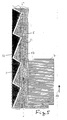
- FIG. 5 shows an embodiment in which the two side edges 11 of the solar plate 5 have sawtooth-shaped projections 12 which lie in correspondingly shaped sawtooth-shaped recesses 13 in the grooves 4.
- the solar panel is inserted in particular from the lower free edge upwards in the direction of arrow 14 into the grooves 4 of the roof tile / roof tile. Since the sawtooth-shaped projections and recesses in the direction of arrow 14 offer a small resistance and, in the opposite direction, a greater resistance, the solar panel is easy to insert and then securely held.
- the recesses can also be missing. In this case, the projections 12 dig into the material of the grooves 4 of the roof tile.
- FIG. 6 shows a type of fastening with lateral, in particular metal brackets 15 on the solar panel, which overlap at least two edges of the roof tile / roof tile, in particular the upper and lower edge, and thus overlap the underside of the roof tile / roof tile.
- the overlapping regions of the roof tile / roof tile are not designed over their entire length, but rather only short projections or tongues 16 which hold the solar panel.
- recesses 17 shaped in the edge of the solar plate corresponding to the projections / tongues 16 can be provided in order to guide the projections / tongues 16 through the recesses 17 when the solar plate is inserted and thus do not have to insert the solar plate over its entire length.
Abstract
Description
Die Erfindung betrifft einen Dachziegel/Dachstein aus einer vollflächigen Platte aus Ton, Keramik, Beton oder Kunststoff als Träger einer an der Oberseite befestigten Solarplatte mit photovoltaischen Solarzellen.The invention relates to a roof tile / roof tile from a full-surface plate made of clay, ceramic, concrete or plastic as a carrier of a solar panel attached to the top with photovoltaic solar cells.
Die Integration der Photovolatic (PV) in die Architektur mit handelsüblichen Modulen stößt auf zahlreiche technische und optische Probleme, DE 19 00 069, DE-GM 79 20 669, DE 34 19 299, DE-GM 82 12 100, DE 33 37 658. So müssen für die Befestigung konventioneller PV.-Module Befestigungselemente durch die Dachhaut auf die tragende Dachkonstruktion montiert werden, die individuell an das jeweilige Dachhautsystem angepaßt werden müssen. Eine Standardisierung ist schwierig und aufgrund kleiner Stückzahlen in Handarbeit kaum kalkulierbar. Die Befestigung der handelsüblichen PV.-Module erfordert sturmfeste und korrosionsgeschützte Konstruktionen, die so fixiert sein müssen, daß sie sich nicht im Laufe der Zeit lockern und klappernde Geräusche verursachen.The integration of photovolatic (PV) in the architecture with commercially available modules encounters numerous technical and optical problems, DE 19 00 069, DE-GM 79 20 669, DE 34 19 299, DE-GM 82 12 100, DE 33 37 658. For the fastening of conventional PV modules, fastening elements have to be mounted through the roof skin on the load-bearing roof structure, which have to be individually adapted to the respective roof skin system. Standardization is difficult and, due to small quantities, can hardly be calculated by hand. Fastening the commercially available PV modules requires storm-proof and corrosion-protected constructions, which must be fixed in such a way that they do not loosen over time and cause rattling noises.
Das Durchstoßen einer konventionellen Dachhaut verursacht zwangsläufig Abdichtungs- und anschließend Dichtigkeitsprobleme. So ist die Langzeitdichtigkeit einer verletzten durchstoßenen Dachhaut durch die täglichen thermischen Spannungen sowie durch die Altersbewegungen des Daches nicht garantiert und kann zu großen Schäden führen. Auch ist diese Befestigungstechnik kostspielig sowohl in den Materialkomponenten als auch im Personalaufwand speziell ausgebildeter Fachkräfte.Puncturing a conventional roof skin inevitably causes sealing and then Tightness problems. The long-term impermeability of an injured, pierced roof skin is not guaranteed by the daily thermal tensions or by the aging movements of the roof and can lead to major damage. This fastening technology is also expensive in terms of both the material components and the personnel costs of specially trained specialists.
Zur unbefriedigenden Technik kommt ein optisch inakzeptabler Eindruck eines auf der traditionellen Dachhaut unharmonisch schwebenden Photovoltaic-Moduls. Eine farbliche Anpassung des blauen oder schwarzen Moduls mit silbernen oder gefärbten Rahmen an die Farbstruktur des Daches ist nicht möglich und stößt auf Ablehnung. Eine Massenproduktion zur Kostendegression der Photovoltaic wird durch diese konventionelle PV.-Technik nicht initiiert.In addition to the unsatisfactory technology, there is an optically unacceptable impression of a photovoltaic module floating inharmoniously on the traditional roof skin. Color matching of the blue or black module with silver or colored frame to the color structure of the roof is not possible and is rejected. Mass production to reduce the costs of photovoltaic is not initiated by this conventional PV technology.
Aufgabe der Erfindung ist es, einen Dachziegel oder Dachstein zu schaffen, der bei einfacher Konstruktion, Herstellung und Montage eine kostengünstige technische und optische Integration der Photovoltaic in die Architektur ermöglicht.The object of the invention is to provide a roof tile or roof tile which, with simple construction, manufacture and installation, enables inexpensive technical and optical integration of the photovoltaic into the architecture.
Diese Aufgabe wird erfindungsgemäß dadurch gelöst, daß die Solarplatte an der Oberseite des Dachziegels/Dachsteins derart formschlüssig befestigt ist, daß zumindest auf zwei einander gegenüberliegenden Seiten das Material des Dachziegels/Dachsteins in der Weise vorsteht, daß es einen Bereich insbesondere Rand der Solarplatte übergreift, so daß die Solarplatte gegen ein Anheben nach oben gesichert ist.This object is achieved in that the solar panel is positively attached to the top of the roof tile / roof tile in such a way that the material of the roof tile / roof tile protrudes at least on two opposite sides in such a way that it overlaps an area, in particular the edge, of the solar panel, so that the solar panel is secured against lifting upwards.
Hierdurch können Befestigungsweisen benutzt werden, die eine Herstellung des Dachziegels bzw. Dachsteins durch übliche Dachziegel-Herstellungsverfahren erlauben und der Dachziegel kann auch ohne Modul zum Decken des Daches verwendet werden.As a result, fastening methods can be used which allow the roof tile or roof tile to be produced by customary roof tile production processes, and the roof tile can also be used without a module for covering the roof.
Ein nachträgliches Anbringen des Moduls ist durch jeden Laien durchführbar.Any layperson can retrofit the module.
Besonders vorteilhaft ist es, wenn die Solarplatte den Dachziegel/Dachstein derart übergreift, daß der Dachziegel/ Dachstein unterfasst wird. Hierbei können zum Untergreifen des Dachziegels/Dachsteins an der Solarplatte seitlich Klammern vorstehen. Eine sehr einfache Konstruktion und Handhabung bei sicherer Befestigung wird erreicht, wenn die Solarplatte ihre befestigte Stellung durch Verschieben in ihrer Ebene erreicht.It is particularly advantageous if the solar panel overlaps the roof tile / roof tile in such a way that the roof tile / roof tile is covered. Here, clips can protrude laterally on the solar panel to reach under the roof tile / roof tile. A very simple construction and handling with secure attachment is achieved when the solar panel reaches its attached position by moving it in its plane.
Auch wird hierzu vorgeschlagen, daß er an der Unterseite als auch an der Oberseite in den Bereichen, die von benachbarten Dachziegeln/Dachsteinen bedeckt werden, die üblichen Dachziegelformen und -falze aufweist.It is also proposed for this purpose that it has the usual roof tile shapes and rabbets on the underside and on the top in the areas which are covered by adjacent roof tiles.
Eine besonders einfache und sichere Befestigung wird erreicht, wenn die Oberseite eine konkave Ausnehmung aufweist, an deren oberen Rand die Solarplatte befestigt ist. Ferner ist hierdurch die Solarplatte hinterlüftet und gekühlt. Auch wird ein Kabelkanal gebildet. Hierbei sollte der obere Rand der konkaven Ausnehmung den Rand der Solarplatte ganz oder abschnittsweise übergreifen. Auch ist hierbei von Vorteil, wenn der Rand der Solarplatte im rillen-, nuten- oder rinnenförmigen Rand formschlüssig einliegt.A particularly simple and secure attachment is achieved if the upper side has a concave recess, on the upper edge of which the solar panel is attached. This also ventilates and cools the solar panel. A cable duct is also formed. The upper edge of the concave recess should overlap the edge of the solar panel in whole or in sections. It is also advantageous here if the edge of the solar panel lies in a form-fitting manner in the groove, groove or groove-shaped edge.
Besonders vorteilhaft für Herstellung und Handhabung ist es, wenn die Solarplatte biegsam ist und sich in die Ausnehmung soweit hineindrücken läßt, daß der Rand der Solarplatte aus der oder den Rille(n), Nute(n) oder Rinne(n) heraustritt bzw. den vorstehenden oberen Randwulst der Ausnehmung schnappend überwindet. Hierzu kann die Ausnehmung den Abschnitt eines Zylindermantels bilden, dessen Achse parallel zur Falllinie des Dachziegels/Dachsteins liegt.It is particularly advantageous for manufacture and handling if the solar plate is flexible and can be pushed into the recess to such an extent that the edge of the solar plate emerges from the groove (s), groove (s) or groove (s) overcomes the protruding upper edge bead of the recess. For this purpose, the recess can form the section of a cylinder jacket whose axis lies parallel to the falling line of the roof tile / roof tile.
Auch ist von Vorteil, wenn der von der Ausnehmung gebildete und von der Solarplatte bedeckte Hohlraum als Kabelkanal und/oder als Belüftungskanal dient. Eine gute Kühlung bei einfachster Form des Kanals wird erreicht, wenn der von der Ausnehmung gebildete und von der Solarplatte bedeckte Hohlraum im oberen und unteren Bereich des Dachziegels/ Dachsteins offen ist.It is also advantageous if the cavity formed by the recess and covered by the solar panel serves as a cable duct and / or as a ventilation duct. Good cooling with the simplest form of the channel is achieved if the cavity formed by the recess and covered by the solar panel is open in the upper and lower areas of the roof tile / roof tile.
Hierbei kann zur Bildung der oberen Öffnung die Solarplatte die Ausnehmung im oberen Bereich nicht bedecken. Auch ist von Vorteil, wenn im Bereich der unteren Öffnung in der Ausnehmungswand ein Schlitz oder eine Kerbe zum Einlegen eines elektrischen Anschlußkabels ist.To form the upper opening, the solar panel cannot cover the recess in the upper area. It is also advantageous if there is a slot or a notch in the area of the lower opening in the recess wall for inserting an electrical connection cable.
Um ein Herausrutschen des Moduls zu verhindern wird vorgeschlagen, daß im Rand der Ausnehmung mindestens ein Vorsprung ist, der in eine Ausnehmung im Rand der Solarplatte eingreift. Ferner kann von Vorteil sein, wenn die Solarplatte in oder an der Ausnehmung angeklebt ist.In order to prevent the module from slipping out, it is proposed that there be at least one projection in the edge of the recess which engages in a recess in the edge of the solar panel. It can also be advantageous if the solar panel is glued in or on the recess.
Eine besonders vorteilhafte zusätzliche oder alternative Befestigungsweise ist, wenn der Dachziegel/Dachstein mehrere Vorsprünge, insbesonder Zapfen aufweist, die in entsprechend geformten Öffnungen der Solarplatte einliegen. Alternativ kann aber auch die Solarplatte mehrere Vorsprünge, insbesondere Zapfen aufweisen, die in entsprechend geformten Öffnungen des Dachziegels/Dachsteins einliegen.A particularly advantageous additional or alternative method of fastening is when the roof tile / roof tile has a plurality of projections, in particular pegs, which lie in correspondingly shaped openings in the solar panel. Alternatively, however, the solar panel can also have a plurality of projections, in particular pegs, which lie in correspondingly shaped openings in the roof tile / roof tile.
Eine architektonische in abfallende Linien aufgeteilte Dachfläche wird erreicht, wenn der von der Solarplatte und dem benachbarten Dachziegel/Dachstein nicht bedeckte abfallende Längsrand des Dachziegels/Dachsteins wulstförmig nach oben gewölbt ist. Eine optische Verbesserung wird erreicht, wenn die Solarplatte eine texturierte, strukturierte, und/oder weichreflektierende Oberfläche aufweist.An architectural roof surface divided into sloping lines is achieved if the sloping longitudinal edge of the roof tile / roof tile, which is not covered by the solar panel and the adjacent roof tile / roof tile, is bulged upward in a bulge. An optical improvement is achieved if the solar panel has a textured, structured, and / or soft-reflecting surface.
Für die Langzeitgebrauchsfähigkeit einer Solarbedachung ist entscheidend, daß die Solarzellen nicht parziell verschmutzen und dadurch an Leistung verlieren. Deshalb wird vorgeschlagen, daß die Solarplatte eine antihaftende, schmutzabweisende Beschichtung aufweist. Eine gute optische Qualität über lange Zeit wird erreicht, wenn die Solarplatte eine herbizide, fungizide und/oder antimoosansetzende Beschichtung aufweist. Auch ist von Vorteil, wenn die Solarplatte im oberen Bereich des Dachziegels/Dachsteins so von der vorderen Kante des überliegenden Ziegels entfernt angebracht ist, daß diese vordere Kante des überliegenden Ziegels keinen Schatten auf die Solarzellen wirft.For the long-term usability of a solar roof, it is crucial that the solar cells do not become partially dirty and thus lose performance. It is therefore proposed that the solar panel have an anti-stick, dirt-repellent coating. Good optical quality over a long period of time is achieved if the solar panel has a herbicidal, fungicidal and / or antimossan coating. It is also advantageous if the solar panel in the upper area of the roof tile / roof tile is attached so far from the front edge of the overlying tile that this front edge of the overlying tile does not cast a shadow on the solar cells.
Ein optimales Aussehen wird erreicht, wenn der Mittelfeld-Dachziegel sowie das Gesamt-Dachziegel/Dachstein-System vorwiegend die gleiche Farbe wie die Solarplatte aufweist. Besonders vorteilhaft ist es, wenn das Dachziegel/Dachstein-System vorwiegend gleiche Reflektionswerte aufweist.An optimal appearance is achieved if the middle field roof tile and the overall roof tile / roof tile system predominantly have the same color as the solar panel. It is particularly advantageous if the roof tile / roof tile system predominantly has the same reflection values.
Von Vorteil ist auch, daß die Solarplatte an der regenablaufenden Kante keine wulstartige, aufwerfende, wasserstauende Umrandung hat.It is also advantageous that the solar panel does not have a bulge-like, raised, water-blocking border at the rain-draining edge.
Ein Ausführungsbeispiel der Erfindung ist in der Zeichnung dargestellt und wird im folgenden näher beschrieben. Es zeigen
- Figur 1
- eine Vorderansicht des Dachziegels/Dachsteins mit oben befestigter Solarplatte,
Figur 2- einen Querschnitt durch den Dachziegel/Dachstein,
Figur 3- einen Ausschnitt aus
Figur 2 in einer ersten Ausführungsform und Figur 4- einen Ausschnitt aus
Figur 2 in einer zweiten Ausführungsform, Figur 5- einen Schnitt durch den Dachziegel/Dachstein in seiner Ebene im Bereich des Seitenrandes der Solarplatte
Figur 6- eine Draufsicht und zwei Seitenansichten eines Dachziegels/Dachsteins, bei dem die Solarplatte durch Klammern befestigt ist.
Figur 7- eine perspektivische Ansicht eines Dachziegels/ Dachsteins mit zugenförmigen Vorsprüngen
Figur 8- einen Schnitt durch einen Dachstein mit wulstförmigen Vorsprüngen, die in seitlichen Nuten der Solarplatte einliegen.
- Figure 1
- a front view of the roof tile / roof tile with solar panel attached above,
- Figure 2
- a cross section through the roof tile / roof tile,
- Figure 3
- a section of Figure 2 in a first embodiment and
- Figure 4
- 2 shows a section from FIG. 2 in a second embodiment,
- Figure 5
- a section through the roof tile in its level in the area of the side edge of the solar panel
- Figure 6
- a plan view and two side views of a roof tile / roof tile, in which the solar panel is fastened by clips.
- Figure 7
- a perspective view of a roof tile with roof-shaped projections
- Figure 8
- a section through a roof tile with bead-shaped projections, which lie in the lateral grooves of the solar panel.
Das Basiselement ist ein Mittelfeld-Dachziegel oder Dachstein 1 in der traditionellen verzahnenden, verpfalzenden, überlappenden Konstruktion. Die vordere Oberfläche 2 des Dachziegels/Dachsteins weist eine teilzylindrische Mulde 3 auf. Die abgesenkte Mulde 3 bzw. Fläche bildet eine Rinne bzw. einen Kanal, öffnet sich nach vorne und steigt im hinteren Teil abgerundet nach oben. In den beiden Längsflanken sind hinterschnittene Nuten 4 mit horizontalen Versätzen (Riffelung) zur Aufnahme der zwei Seitenränder des rahmenlosen Photovoltaic-Moduls 5 eingearbeitet.The basic element is a middle field roof tile or roof tile 1 in the traditional interlocking, interlocking, overlapping construction. The
Dieser Dachziegel/Dachstein wird konventionell vom ortsansässigen Dachdecker nach traditioneller Handwerksart und DIN-Vorschriften verlegt. Das gesamte Dach des Hauses ist aufgrund der traditionellen Dachziegel/DachsteinKonstruktion schlagregen-schneesturmfest-dicht. Aus dem Gesamtdachziegelsystem (wie z.B. des Reformziegels) mit Ortsgang-, First-, Entlüfter-Halbziegeln ist lediglich der Mittelfeldziegel in der Oberfläche umgestaltet.This roof tile / roof tile is laid conventionally by the local roofer according to traditional craftsmanship and DIN regulations. The entire roof of the house is due to the traditional roof tile / roof stone construction driving rain-snow storm-tight. From the overall roof tile system (such as the reform tile) with local aisle, ridge, vent half-tiles, only the middle field tile has been redesigned.
Das gesamte Dachziegel/Dachstein-System ist solarzellen-blau mit gleichen Reflektionswerten wie der Photovoltaic-Modul, damit ist die Gleichmäßigkeit und optische Harmonie des Daches gewährleistet.The entire roof tile / roof tile system is solar cell blue with the same reflection values as the photovoltaic module, thus ensuring the uniformity and visual harmony of the roof.
Eine architektonische in abfallenden Linien aufgeteilte Dachfläche wird erreicht, wenn der von der Solarplatte 5 und dem benachbarten Dachziegel/Dachstein 1 nicht bedeckte abfallende Längsrand 1c des Dachziegels wulstförmig nach oben gewölbt ist.An architectural roof surface divided into sloping lines is achieved if the sloping longitudinal edge 1c of the roof tile, which is not covered by the
Das zweite Element des Dachziegel/Dachstein-Systems ist das Photovoltaic-Modul 5. Dieser PV.-Modul 5 besteht aus einer dünnen 1,5 - 2,0 mm starken chemisch gehärteten, eisenfreien, hochlichttransparenten Glasscheibe 6. Unter diese Scheibe 6 sind Solarzellen 7 in Schindeltechnik in speziellen witterungsbeständigen Kunststofffolien einlamminiert. Der Einbettungskunststoff ist um die Glasscheibe 6 herumgezogen. Diese spezielle Lamminiertechnik garantiert einen mechanischen sowie chemischen Kantenschutz der Glasscheibe 6. Durch die Profilierung des Kantenschutzes wird eine sturmfeste Adaption des Moduls 5 an dem Dachziegel/Dachstein 1 gewährleistet.The second element of the roof tile / roof tile system is the
Der untere rückseitige Abschluß des PV.-Moduls 5 bildet eine schwarze Folie 8 mit hohen Temperatur-Emmissions-Koeffizient zur schnellen effektiven rückseitigen Ableitung der Wärme an den Solarzellen 7.Durch diese Konstruktion wird der Tages- bzw. Jahreswirkungsgrad des Photovoltaic-Dachziegel/ Dachstein-Systems wesentlich erhöht.The lower rear end of the
Die Solarplatte hat an der regenablaufenden Kante keine wulstartige, aufwerfende, wasserstauende Umrandung. Der Dachziegel/Dachstein und das Dachziegel/Dachstein-System weisen eine gleiche und/oder unterschiedliche Einfärbung wie die Solarplatte auf. Die Solarplatte und der Dachziegel/ Dachstein weisen gleiche Reflektionswerte auf. Die Solarplatte ist reflektionsfrei.The solar panel has no bulge-like, throwing-on, water-blocking edges on the rain-draining edge. The roof tile / roof tile and the roof tile / roof tile system have the same and / or different coloring as the solar panel. The solar panel and the roof tile / roof tile have the same reflection values. The solar panel is reflection-free.
Auch kann in einer Ausführung die Solarplatte an der regenablaufenden Kante keine wulstartige, aufwerfende, wasserstauende Umrandung haben. Drei Reihen Solarzellen 7 in überlappender Schindeltechnik mit je sechs Einzelzellen in der Größe von 25 x 100 x 0,2 mm sind in dem Modul 5 eingebettet. Die überlappende Schindeltechnik der verschalteten Solarzellen 7 gewährleistet ein optisch einheitliches metallisch blaues Erscheinungsbild ohne störende silbere Kontaktbänder. Durch den Einsatz von 18 Hochleistungszellen 7 ist eine optimale Stromerzeugung ohne hohe Verluste gewährleistet. Die Leerlaufspannung liegt bei ca. 9 Volt, die Arbeits-Ladespannung liegt bei ca. 6 Volt. Bei einem Wirkungsgrad von 14% erzeugt der Modul bei vollem Sonnenschein (1 kw/m² eine Leistung von 6,3 Watt. Für einen m²- Dachfläche werden 14,5 Pfannen benötigt, dies ergibt eine m²-Leistung von 91,3 Watt.Also, in one embodiment, the solar panel on the rain-draining edge cannot have a bead-like, raised, water-blocking border. Three rows of
Die elektrischen Anschlüsse an die Solarzellen 7 bestehen aus solarzellen-farbigen Kabeln 9, die aus dem Laminat witterungsfest herausgezogen sind. Die elektrische Verbindung der Module 5 untereinander erfolgt durch eine Quetschverbindung mit anschließender Verlötung und dichte Verkapselung über hoch-witterungsbeständige Schrumpfschläuche. Dies gewährt eine Langzeitverschaltung ohne Korrosion und Leistungsverlusten. In jede Kabelverbindung der Dachziegel/Dachstein-Module wird eine Rückstromdiode einlamminiert. Diese Rückstromdiode garantiert bei parziellen Abschattungen die Funktionsfähigkeit der Dachziegel/Dachstein-Module.The electrical connections to the
Zunächst wird das gesamte Dach traditionell vom ortsansässigen konventionellen Dachdecker mit Dachziegeln/ Dachsteinen ohne Module gedeckt. Anschließend werden nachträglich vom PV.-Elektriker die Photovoltaic-Module in den Mittelfeldziegel/-stein eingedrückt, fixiert und elektrisch miteinander verkabelt. Ein Druck auf den Ziegel/ Stein aufliegenden PV.-Modul wölbt diesen so nach innen, so daß sich seine Breite verkleinert. Dadurch rutscht er über die Kanten 4a der Längsnuten nach innen. Bei Entspannen dehnt sich der PV.-Modul in die Längsnuten ein. Er wird unverrückbar sturm- und langzeitfest in den Nuten fixiert.First of all, the entire roof is traditionally covered by the local conventional roofer with roof tiles / roof tiles without modules. The photovoltaic modules are then pressed into the middle field brick / brick by the PV electrician, fixed and electrically wired together. Pressing the PV module lying on the brick / stone bulges it inwards so that its width is reduced. As a result, it slides inward over the
Der Photovoltaic-Modul bildet mit dem Tal des Ziegels/Dachsteins den offenen Kanal 3. Die Innenhöhe liegt bei ca. 25 mm, die Breite bei ca. 160 mm. Nach vorne öffnet sich der Kanal senkrecht. Der PV.-Modul ist so konstruiert, daß er ca. 20 mm kürzer ist als das Tal im Ziegel/Stein. Es entsteht so eine horizontale Kanalöffnung 1b im hinteren Ziegel/Steinbereich. Diese hintere Öffnung 1b liegt ca. 25 mm vor der senkrechten Kanalöffnung 1a des darüberliegenden Ziegels/Steins. Durch diese Anordnung liegt die vordere Kante des überlappenden Dachziegels/Steins ca. 25 mm von dem darunter liegenden PV.-Dachziegel/Stein- Moduls entfernt. Dies bedeutet bei Schrägdächern, daß ein senkrechter Sonnenstrahl keine Abschattung des überliegenden Dachziegels/Steins auf den unterliegenden PV.-Modul erzeugt. Der Jahreswirkungsgrad wird dadurch wesentlich verbessert.The photovoltaic module forms the
- 1. Als belüftender Kühlkanal für die Wärmeabfuhr an den Solarzellen.1. As a ventilating cooling duct for heat dissipation to the Solar cells.
- 2. als Kabelschacht für die elektrische Verbindung der Module untereinander.2. as a cable duct for the electrical connection of the modules to each other.
Jeder Ziegel/Stein 1 hat seinen eigenen Kanal 3. Die Einzelkanäle 3 der PV.-Dachziegel/Steine sind nicht miteinander verbunden. Eine kleine Nut 10 an der vorderen Kante des Ziegels/Steins dient zur Fixierung und unauffälligen Verlegung der elektrischen Kabel 9, damit auch bei Sturm die Kabel 9 sich nicht lösen können und klappernde Geräusche entstehen können.Each tile / stone 1 has its
Das Gewicht des Photovoltaic-Ziegels/Steins liegt bei ca. 3,5 kg und garantiert damit eine sturmfeste Auflage der Ziegel/Steine auf die Sparrenkonstruktion des Photovoltaic-Dachziegel/-stein-Systems. Die Photovoltaic-Module sind weitgehend wartungsfrei und garantieren eine Langzeitstabilität. Falls durch mechanische Einwirkungen PV.-Module defekt werden sollten, so können sie einfach und problemlos ausgetauscht werden, ohne daß der Ziegel/ Steinverband aufgedeckt werden muß. Durch Wölbung des PV.-Moduls nach oben wird er aus dem Ziegel/Stein ohne Mühe entfernt und kann gegen einen neuen PV.-Modul ausgetauscht werden.The weight of the photovoltaic tile is approx.3.5 kg and thus guarantees a storm-proof support of the tiles on the rafter construction of the photovoltaic roof tile system. The photovoltaic modules are largely maintenance-free and guarantee long-term stability. If PV modules should become defective due to mechanical influences, they can be replaced easily and without problems, without the brick / stone structure having to be uncovered. By arching the PV module upwards, it is easily removed from the brick / stone and can be exchanged for a new PV module.
Ein weiterer Vorteil des Photovoltaic-Dachziegel/-stein-Systems besteht in der nachträglichen suzessiven Erweiterung des Solargenerators, ohne daß das Dach verändert oder neu gedeckt werden muß. Je nach Finanzlage des Bauherren kann er nachträglich die photovoltaische Stromerzeugung auf seinem Dach erweitern und ausbauen.Another advantage of the photovoltaic roof tile / brick system is the subsequent successive expansion of the solar generator without the roof having to be changed or re-covered. Depending on the financial situation of the builder, he can subsequently expand and expand the photovoltaic power generation on his roof.
Die Zweikomponenten-Technologie des Photovoltaic-Dachziegel/-stein-Systems ermöglicht eine konventionelle, traditionelle Bedachung des Hauses mit anschließender nachträglicher auch schrittweiser Installation der Photovoltaic-Dachziegel/-stein-Module zum Aufbau einer zukunftsträchtigen Energieversorgung von der Sonne.The two-component technology of the photovoltaic roof tile system enables conventional, traditional roofing of the house with subsequent Subsequent and step-by-step installation of the photovoltaic roof tile / brick modules to build a promising energy supply from the sun.
Figur 5 zeigt eine Ausführungsform, bei der die zwei Seitenränder 11 der Solarplatte 5 sägezahnförmige Vorsprünge 12 aufweisen, die in entsprechend geformten sägezahnförmigen Ausnehmungen 13 der Nuten 4 einliegen. Die Solarplatte wird insbesondere vom unteren freien Rand aus nach oben in Richtung des Pfeiles 14 in die Nuten 4 des Dachziegels/Dachsteins eingeschoben. Da die sägezahnförmigen Vorsprünge und Rücksprünge in Richtung des Pfeiles 14 einen kleinen und entgegengesetzt einen größeren Widerstand bieten, ist die Solarplatte leicht einschiebbar und danach sicher gehalten. Die Ausnehmungen können auch fehlen. In diesem Fall graben sich die Vorsprünge 12 in das Material der Nuten 4 des Dachziegels/Dachsteins ein.FIG. 5 shows an embodiment in which the two
Figur 6 zeigt eine Befestigungsart mit seitlichen, insbesondere metallenen Klammern 15 an der Solarplatte, die mindestens zwei Ränder des Dachziegels/Dachsteins, insbesondere den oberen und unteren Rand, übergreifen und damit die Unterseite des Dachziegels/Dachsteins übergreifen.FIG. 6 shows a type of fastening with lateral, in
Bei den Ausführungsbeispielen nach Figuren 7 und 8 sind die übergreifenden Bereiche des Dachziegels/Dachsteins nicht über seine gesamte Länge ausgeführt, sondern nur kurze Vorsprünge oder Zungen 16, die die Solarplatte halten. Hierbei können im Rand der Solarplatte entsprechend den Vorsprüngen/Zungen 16 geformte Ausnehmungen 17 sein, um beim Einsetzen der Solarplatte die Vorsprünge/Zungen 16 durch die Ausnehmungen 17 zu führen und damit die Solarplatte nicht über ihre gesamte Länge einschieben zu müssen.In the exemplary embodiments according to FIGS. 7 and 8, the overlapping regions of the roof tile / roof tile are not designed over their entire length, but rather only short projections or
Claims (17)
Applications Claiming Priority (2)
| Application Number | Priority Date | Filing Date | Title |
|---|---|---|---|
| DE4002711A DE4002711A1 (en) | 1990-01-31 | 1990-01-31 | ROOF TILE WITH SOLAR PANEL |
| DE4002711 | 1990-01-31 |
Publications (2)
| Publication Number | Publication Date |
|---|---|
| EP0440103A2 true EP0440103A2 (en) | 1991-08-07 |
| EP0440103A3 EP0440103A3 (en) | 1991-12-27 |
Family
ID=6399072
Family Applications (1)
| Application Number | Title | Priority Date | Filing Date |
|---|---|---|---|
| EP19910100962 Withdrawn EP0440103A3 (en) | 1990-01-31 | 1991-01-25 | Roofing tile or roofing stone with solar plate |
Country Status (3)
| Country | Link |
|---|---|
| US (1) | US5112408A (en) |
| EP (1) | EP0440103A3 (en) |
| DE (1) | DE4002711A1 (en) |
Cited By (14)
| Publication number | Priority date | Publication date | Assignee | Title |
|---|---|---|---|---|
| DE4139753A1 (en) * | 1991-12-03 | 1993-06-09 | Juergen O-4090 Halle-Neustadt De Scherzberg | Solar cell assembly converting solar radiation into electric energy - is directly fitted to roof slabs, tiles, or roof shaped assembly |
| EP0547285A1 (en) * | 1991-12-17 | 1993-06-23 | Rieter-Werke Händle Kg | Solar roofing tile and process for manufacturing same |
| WO1995008193A1 (en) * | 1993-09-16 | 1995-03-23 | Blue Planet Ag | Solar module with perforated plate |
| WO1995008194A1 (en) * | 1993-09-16 | 1995-03-23 | Blue Planet Ag | Solar roofing tile/slab |
| DE4331425A1 (en) * | 1993-09-16 | 1995-03-23 | Bmc Solar Ind Gmbh | Solar module with perforated panel |
| DE4411458A1 (en) * | 1993-09-16 | 1995-03-30 | Bmc Solar Ind Gmbh | Roofing tile |
| DE4332873A1 (en) * | 1993-09-27 | 1995-03-30 | Rieter Werke Haendle | Roofing element for recovering electric energy, and process for the production thereof |
| WO1996009651A1 (en) * | 1994-09-22 | 1996-03-28 | Blue Planet Ag | Method of securing solar panels |
| DE19609005A1 (en) * | 1996-03-08 | 1997-09-11 | Markus Reinacher | Solar collector or photovoltaic apparatus for housing with tile roof |
| EP0907209A1 (en) * | 1997-10-03 | 1999-04-07 | Kämpfer & Co. | Roof tile |
| EP1573145A4 (en) * | 2002-02-20 | 2008-03-12 | Powerlight Corp | Shingle assembly |
| WO2009074167A1 (en) * | 2007-12-12 | 2009-06-18 | Francisco Ruiz Caballero | Photovoltaic solar roof |
| ITFI20090260A1 (en) * | 2009-12-15 | 2011-06-16 | Martino Mario Di | PANEL HOLDER TILE. |
| WO2018178755A1 (en) | 2017-03-31 | 2018-10-04 | Gaddam Vamsi Krishna | Eco-friendly energy generating roofs |
Families Citing this family (64)
| Publication number | Priority date | Publication date | Assignee | Title |
|---|---|---|---|---|
| US5316592A (en) * | 1992-08-31 | 1994-05-31 | Dinwoodie Thomas L | Solar cell roofing assembly |
| JP3570738B2 (en) * | 1993-07-28 | 2004-09-29 | 富士電機ホールディングス株式会社 | Solar power roof |
| US5437735A (en) * | 1993-12-30 | 1995-08-01 | United Solar Systems Corporation | Photovoltaic shingle system |
| US5505788A (en) * | 1994-06-29 | 1996-04-09 | Dinwoodie; Thomas L. | Thermally regulated photovoltaic roofing assembly |
| DE4434207A1 (en) * | 1994-09-24 | 1996-03-28 | Blue Planet Ag | Solar panel |
| US5651226A (en) * | 1995-02-10 | 1997-07-29 | Archibald; John P. | Tile with solar energy collection capability |
| WO1997015953A1 (en) * | 1995-10-20 | 1997-05-01 | Real, Markus | Solar cell-concrete module |
| US5746839A (en) | 1996-04-08 | 1998-05-05 | Powerlight Corporation | Lightweight, self-ballasting photovoltaic roofing assembly |
| ATE177682T1 (en) * | 1996-12-13 | 1999-04-15 | Jung & Lindig Bleiind | TIN PLATED LEAD SHEET |
| US6061978A (en) * | 1997-06-25 | 2000-05-16 | Powerlight Corporation | Vented cavity radiant barrier assembly and method |
| USD408554S (en) * | 1997-06-25 | 1999-04-20 | Powerlight Corporation | Solar electric shade system |
| US6148570A (en) * | 1998-02-05 | 2000-11-21 | Powerlight Corporation | Photovoltaic building assembly with continuous insulation layer |
| AUPP558698A0 (en) * | 1998-08-31 | 1998-09-24 | Pacific Solar Pty Limited | Frame for mounting a panel or the like to a roof |
| AU757134B2 (en) * | 1998-08-31 | 2003-02-06 | Pacific Solar Pty Limited | Panel mounting frame and method |
| EP1071137A3 (en) * | 1999-07-21 | 2007-03-21 | Kaneka Corporation | Roofing tile having photovoltaic module to generate power |
| US6689950B2 (en) * | 2001-04-27 | 2004-02-10 | The Boeing Company | Paint solar cell and its fabrication |
| US6870087B1 (en) * | 2001-09-14 | 2005-03-22 | Patrick Gallagher | Assembly method and apparatus for photovoltaic module |
| US6617507B2 (en) | 2001-11-16 | 2003-09-09 | First Solar, Llc | Photovoltaic array |
| AUPS038702A0 (en) * | 2002-02-08 | 2002-02-28 | Sustainable Technologies International | Construction products with integrated photovoltaics |
| US6883290B2 (en) | 2002-02-20 | 2005-04-26 | Powerlight Corporation | Shingle system and method |
| US20030154667A1 (en) * | 2002-02-20 | 2003-08-21 | Dinwoodie Thomas L. | Shingle system |
| CN1295412C (en) * | 2002-02-25 | 2007-01-17 | 甘贝尔有限公司 | Method for integrated covering single-pitch roof by using photocell board and large tile forming covering material |
| US6959517B2 (en) * | 2003-05-09 | 2005-11-01 | First Solar, Llc | Photovoltaic panel mounting bracket |
| CA2539419C (en) * | 2003-08-20 | 2012-01-03 | Powerlight Corporation | Pv wind performance enhancing methods and apparatus |
| US20050263181A1 (en) * | 2004-05-25 | 2005-12-01 | Kuo-Yow Yen | Photovoltaic cooling frame |
| US7531733B2 (en) * | 2004-06-21 | 2009-05-12 | Mark David Steele | Electronic drum pedal |
| US20060266352A1 (en) * | 2005-05-31 | 2006-11-30 | Finley Shapiro Consulting, Inc. | Self-ballasting solar array mount |
| US9279415B1 (en) | 2005-07-07 | 2016-03-08 | Sunlink Corporation | Solar array integration system and methods therefor |
| WO2007079382A2 (en) * | 2005-12-28 | 2007-07-12 | Sunpower Corporation, Systems | Supported pv module assembly |
| US20080035140A1 (en) * | 2006-05-26 | 2008-02-14 | Bp Corporation North America Inc. | Solar Roof Tile |
| WO2008052816A1 (en) * | 2006-11-02 | 2008-05-08 | Mind S.R.L. | Modular photovoltaic element for building roofs |
| US8003882B2 (en) * | 2006-11-07 | 2011-08-23 | General Electric Company | Methods and systems for asphalt roof integrated photovoltaic modules |
| US20080178923A1 (en) * | 2007-01-29 | 2008-07-31 | Lucky Power Technology Co., Ltd. | Power generation diode module in roof tile |
| WO2008137966A2 (en) * | 2007-05-07 | 2008-11-13 | Robert Stancel | Structures for low cost, reliable solar roofing |
| EP2171769A2 (en) * | 2007-06-28 | 2010-04-07 | Husnu M. Kalkanoglu | Photovoltaic roofing tiles and methods for making them |
| US8536442B2 (en) * | 2007-09-02 | 2013-09-17 | Nanosolar, Inc. | Slidable mounting system for solar modules |
| US9178465B2 (en) | 2007-11-06 | 2015-11-03 | Certainteed Corporation | Photovoltaic roofing elements including tie layer systems and roofs using them |
| US8438796B2 (en) * | 2007-11-06 | 2013-05-14 | Certainteed Corporation | Photovoltaic roofing elements including tie layer systems, and roofs using them, and methods for making them |
| JP5197733B2 (en) * | 2008-02-28 | 2013-05-15 | 京セラ株式会社 | Solar power system |
| US8522490B1 (en) * | 2008-06-11 | 2013-09-03 | Nanosolar, Inc. | Solar module mounting apparatus allowing for at least one degree of freedom |
| US8413391B2 (en) | 2008-10-13 | 2013-04-09 | Sunlink Corporation | Solar array mounting system with universal clamp |
| US8468754B2 (en) | 2009-01-08 | 2013-06-25 | Building Materials Investment Corporation | Shingled roof with integrated photovoltaic collectors |
| US8646228B2 (en) * | 2009-03-24 | 2014-02-11 | Certainteed Corporation | Photovoltaic systems, methods for installing photovoltaic systems, and kits for installing photovoltaic systems |
| FR2947099B1 (en) * | 2009-06-17 | 2013-11-15 | Cynegy Holdings France | PHOTOVOLTAIC TILE FOR ROOF |
| US20110047902A1 (en) * | 2009-09-03 | 2011-03-03 | Philip Cryar | Photovoltaic shingle |
| SG170625A1 (en) * | 2009-10-13 | 2011-05-30 | Alternative Energy Technology Pte Ltd | Photovoltaic cell support assembly |
| US8215071B2 (en) * | 2010-02-02 | 2012-07-10 | Sunpower Corporation | Integrated composition shingle PV system |
| US8424256B2 (en) * | 2010-04-01 | 2013-04-23 | Thomas Lawson Cook | Asphalt roof integrated photovoltaic |
| US8201382B1 (en) | 2010-12-22 | 2012-06-19 | Frank Pao | Building integrated thermal electric hybrid roofing system |
| US8365500B2 (en) | 2010-12-22 | 2013-02-05 | Frank Pao | Optimized building integrated hybrid roofing system |
| US8946542B1 (en) * | 2011-06-24 | 2015-02-03 | Sunedison, Inc. | Solar module bonding method integrated into a pan structure |
| US9038329B2 (en) | 2011-10-11 | 2015-05-26 | Sunlink Corporation | Structure following roof mounted photovoltaic system |
| WO2014006630A1 (en) * | 2012-07-05 | 2014-01-09 | Dow Global Technologies Llc | Flexible building integrated pv device |
| DE102013002113B4 (en) * | 2013-02-08 | 2017-04-13 | Obermeier - Widmann GbR (vertretungsberechtigte Gesellschafter August Obermeier, 84419 Schwindegg; Christine Widmann, 92318 Neumarkt) | Photovoltaic module with a strip-shaped element made of copper for the formation of fungicidal and bactericidal substances |
| US10985688B2 (en) | 2017-06-05 | 2021-04-20 | Tesla, Inc. | Sidelap interconnect for photovoltaic roofing modules |
| US10508448B2 (en) | 2017-09-11 | 2019-12-17 | Lala Khajani | Tile and method of production |
| US10862420B2 (en) | 2018-02-20 | 2020-12-08 | Tesla, Inc. | Inter-tile support for solar roof tiles |
| CN117040435A (en) * | 2018-03-01 | 2023-11-10 | 特斯拉公司 | System and method for packaging photovoltaic roof tiles |
| US10490682B2 (en) | 2018-03-14 | 2019-11-26 | National Mechanical Group Corp. | Frame-less encapsulated photo-voltaic solar panel supporting solar cell modules encapsulated within multiple layers of optically-transparent epoxy-resin materials |
| US11245354B2 (en) | 2018-07-31 | 2022-02-08 | Tesla, Inc. | Solar roof tile spacer with embedded circuitry |
| CN108915159A (en) * | 2018-08-02 | 2018-11-30 | 泗县汉能诚信电气工程有限公司 | A kind of novel B IPV photovoltaic roof |
| US11245355B2 (en) | 2018-09-04 | 2022-02-08 | Tesla, Inc. | Solar roof tile module |
| CN110258973B (en) * | 2019-06-11 | 2021-04-13 | 河源市源日通能源有限公司 | High borosilicate light and heat glass photovoltaic tile |
| ES2951894A1 (en) | 2022-03-16 | 2023-10-25 | Flexbrick S L | PHOTOELECTRIC BUILDING BLOCK (Machine-translation by Google Translate, not legally binding) |
Citations (6)
| Publication number | Priority date | Publication date | Assignee | Title |
|---|---|---|---|---|
| DE1900069A1 (en) * | 1969-01-02 | 1970-09-17 | Otto Hahn | Component for covering roofs |
| FR2455664A1 (en) * | 1979-05-02 | 1980-11-28 | Dupre Jack | Roof tile containing solar cell - comprises two shells forming conventional tile shape to fit into roof |
| DE2929220A1 (en) * | 1979-07-19 | 1981-02-05 | Wieneke Franz | Tiled roof solar energy collectors - have cascade air ducts formed in covered gaps between external collector elements and tiles |
| FR2478167A1 (en) * | 1980-01-16 | 1981-09-18 | Mera Beraldi Yves | Solar roof tile for hot water or electricity prodn. - has heat absorber or photovoltaic element below glass panel incorporated in tile surface |
| DE3314637A1 (en) * | 1982-04-27 | 1983-11-17 | BM CHEMIE Kunststoff GmbH, 5678 Wermelskirchen | Roofing tile |
| DE8236028U1 (en) * | 1982-12-22 | 1988-07-07 | Volksbank Remscheid Eg, 5630 Remscheid, De |
Family Cites Families (10)
| Publication number | Priority date | Publication date | Assignee | Title |
|---|---|---|---|---|
| DE2818474A1 (en) * | 1978-04-27 | 1979-10-31 | Bauer Geb Koerzdorfer Ingeborg | Solar energy conversion roof - with solar cells contained in individual tiles and coupled to bus bars (BR 21.8.79) |
| DE2806810A1 (en) * | 1978-02-17 | 1979-08-23 | Werner Burde | Solar collecting panel for roof - has solar cells behind transparent glass and forms unit with same shape and fixings as normal roofing tile |
| DE7920669U1 (en) * | 1979-07-19 | 1980-03-13 | Wieneke, Franz, Prof. Dr.-Ing., 3406 Bovenden | KIT FOR CONVERTING COVERING ELEMENTS TO SOLAR COLLECTORS |
| DE8212100U1 (en) * | 1982-04-27 | 1983-12-15 | Imchemie Kunststoff Gmbh, 5632 Wermelskirchen | DACHSTEIN |
| FR2550007A1 (en) * | 1983-07-29 | 1985-02-01 | Sanyo Electric Co | Method for producing a semiconducting film and photovoltaic device obtained by the method |
| DE3337658A1 (en) * | 1983-10-17 | 1985-04-25 | BM CHEMIE Kunststoff GmbH, 5678 Wermelskirchen | Large-area solar panel comprising semiconductor photocells |
| DE3419299A1 (en) * | 1984-05-24 | 1985-11-28 | Telefunken electronic GmbH, 7100 Heilbronn | Module for photovolteic solar cells |
| DE3715535A1 (en) * | 1987-05-09 | 1988-11-17 | Hans Joachim Dipl P Kirschning | Glass roof-tiles which act as solar-cells - produced by plastic deformation of float glass material |
| JPH0715942Y2 (en) * | 1988-03-28 | 1995-04-12 | ワイケイケイ株式会社 | Solar energy collector equipment |
| US4886554A (en) * | 1988-09-29 | 1989-12-12 | Gaf Corporation | Solar roofing assembly |
-
1990
- 1990-01-31 DE DE4002711A patent/DE4002711A1/en not_active Withdrawn
-
1991
- 1991-01-25 EP EP19910100962 patent/EP0440103A3/en not_active Withdrawn
- 1991-01-31 US US07/648,489 patent/US5112408A/en not_active Expired - Fee Related
Patent Citations (6)
| Publication number | Priority date | Publication date | Assignee | Title |
|---|---|---|---|---|
| DE1900069A1 (en) * | 1969-01-02 | 1970-09-17 | Otto Hahn | Component for covering roofs |
| FR2455664A1 (en) * | 1979-05-02 | 1980-11-28 | Dupre Jack | Roof tile containing solar cell - comprises two shells forming conventional tile shape to fit into roof |
| DE2929220A1 (en) * | 1979-07-19 | 1981-02-05 | Wieneke Franz | Tiled roof solar energy collectors - have cascade air ducts formed in covered gaps between external collector elements and tiles |
| FR2478167A1 (en) * | 1980-01-16 | 1981-09-18 | Mera Beraldi Yves | Solar roof tile for hot water or electricity prodn. - has heat absorber or photovoltaic element below glass panel incorporated in tile surface |
| DE3314637A1 (en) * | 1982-04-27 | 1983-11-17 | BM CHEMIE Kunststoff GmbH, 5678 Wermelskirchen | Roofing tile |
| DE8236028U1 (en) * | 1982-12-22 | 1988-07-07 | Volksbank Remscheid Eg, 5630 Remscheid, De |
Cited By (17)
| Publication number | Priority date | Publication date | Assignee | Title |
|---|---|---|---|---|
| DE4139753A1 (en) * | 1991-12-03 | 1993-06-09 | Juergen O-4090 Halle-Neustadt De Scherzberg | Solar cell assembly converting solar radiation into electric energy - is directly fitted to roof slabs, tiles, or roof shaped assembly |
| EP0547285A1 (en) * | 1991-12-17 | 1993-06-23 | Rieter-Werke Händle Kg | Solar roofing tile and process for manufacturing same |
| DE4411458C2 (en) * | 1993-09-16 | 1998-10-08 | Blue Planet Ag | Roof tile |
| WO1995008193A1 (en) * | 1993-09-16 | 1995-03-23 | Blue Planet Ag | Solar module with perforated plate |
| WO1995008194A1 (en) * | 1993-09-16 | 1995-03-23 | Blue Planet Ag | Solar roofing tile/slab |
| DE4331425A1 (en) * | 1993-09-16 | 1995-03-23 | Bmc Solar Ind Gmbh | Solar module with perforated panel |
| DE4411458A1 (en) * | 1993-09-16 | 1995-03-30 | Bmc Solar Ind Gmbh | Roofing tile |
| US5768831A (en) * | 1993-09-16 | 1998-06-23 | Blue Planet Ag | Rooftile support for photocell panel |
| US5776262A (en) * | 1993-09-16 | 1998-07-07 | Blue Planet Ag | Solar module with perforated plate |
| DE4332873A1 (en) * | 1993-09-27 | 1995-03-30 | Rieter Werke Haendle | Roofing element for recovering electric energy, and process for the production thereof |
| WO1996009651A1 (en) * | 1994-09-22 | 1996-03-28 | Blue Planet Ag | Method of securing solar panels |
| DE19609005A1 (en) * | 1996-03-08 | 1997-09-11 | Markus Reinacher | Solar collector or photovoltaic apparatus for housing with tile roof |
| EP0907209A1 (en) * | 1997-10-03 | 1999-04-07 | Kämpfer & Co. | Roof tile |
| EP1573145A4 (en) * | 2002-02-20 | 2008-03-12 | Powerlight Corp | Shingle assembly |
| WO2009074167A1 (en) * | 2007-12-12 | 2009-06-18 | Francisco Ruiz Caballero | Photovoltaic solar roof |
| ITFI20090260A1 (en) * | 2009-12-15 | 2011-06-16 | Martino Mario Di | PANEL HOLDER TILE. |
| WO2018178755A1 (en) | 2017-03-31 | 2018-10-04 | Gaddam Vamsi Krishna | Eco-friendly energy generating roofs |
Also Published As
| Publication number | Publication date |
|---|---|
| US5112408A (en) | 1992-05-12 |
| DE4002711A1 (en) | 1991-08-08 |
| EP0440103A3 (en) | 1991-12-27 |
Similar Documents
| Publication | Publication Date | Title |
|---|---|---|
| EP0440103A2 (en) | Roofing tile or roofing stone with solar plate | |
| EP2196594B1 (en) | Element for cladding buildings | |
| EP1703037B1 (en) | Roof or wall covering | |
| EP1953305B1 (en) | Weather-proof building cladding | |
| DE10132557C2 (en) | Mounting profile for mounting photovoltaic modules and mounting system | |
| DE4444439C2 (en) | Solar energy system and receiving element and ridge connecting element therefor | |
| EP1362967B1 (en) | Device with flat, panel shaped building elements | |
| EP0719459A1 (en) | Solar roofing tile/slab | |
| WO1995008193A1 (en) | Solar module with perforated plate | |
| CH684202A5 (en) | Roof covering and structural element with solar cells | |
| EP2277204A2 (en) | Device for generating solar power | |
| EP1060520A1 (en) | Frame made of shaped sections and designed for plate-like elements, and array of several such frames | |
| DE3623428C2 (en) | ||
| DE202009012546U1 (en) | Mounting system for solar systems | |
| DE4408508A1 (en) | Solar cell roof tile | |
| CH689568A5 (en) | Component to build a roof. | |
| DE102008037734A1 (en) | Solar module for a solar system, in particular photovoltaic system | |
| DE4411458A1 (en) | Roofing tile | |
| DE202019002746U1 (en) | Mounting profile for solar modules for in-roof systems | |
| DE2839362C2 (en) | ||
| DE202011102874U1 (en) | Sun protection device with solar element | |
| DE19521098A1 (en) | Roof tile with photoelectric cells or solar tile | |
| DE102010034841B4 (en) | Roof panel and roofing system | |
| DE19609005A1 (en) | Solar collector or photovoltaic apparatus for housing with tile roof | |
| EP2617914A1 (en) | Roof slab and roof covering system |
Legal Events
| Date | Code | Title | Description |
|---|---|---|---|
| PUAI | Public reference made under article 153(3) epc to a published international application that has entered the european phase |
Free format text: ORIGINAL CODE: 0009012 |
|
| AK | Designated contracting states |
Kind code of ref document: A2 Designated state(s): AT BE CH DE DK ES FR GB GR IT LI LU NL SE |
|
| PUAL | Search report despatched |
Free format text: ORIGINAL CODE: 0009013 |
|
| AK | Designated contracting states |
Kind code of ref document: A3 Designated state(s): AT BE CH DE DK ES FR GB GR IT LI LU NL SE |
|
| STAA | Information on the status of an ep patent application or granted ep patent |
Free format text: STATUS: THE APPLICATION IS DEEMED TO BE WITHDRAWN |
|
| 18D | Application deemed to be withdrawn |
Effective date: 19920628 |