EP0486310A2 - Method and system for reproducing images - Google Patents
Method and system for reproducing images Download PDFInfo
- Publication number
- EP0486310A2 EP0486310A2 EP91310537A EP91310537A EP0486310A2 EP 0486310 A2 EP0486310 A2 EP 0486310A2 EP 91310537 A EP91310537 A EP 91310537A EP 91310537 A EP91310537 A EP 91310537A EP 0486310 A2 EP0486310 A2 EP 0486310A2
- Authority
- EP
- European Patent Office
- Prior art keywords
- image
- image data
- storage medium
- images
- stored
- Prior art date
- Legal status (The legal status is an assumption and is not a legal conclusion. Google has not performed a legal analysis and makes no representation as to the accuracy of the status listed.)
- Ceased
Links
Images


Classifications
-
- G—PHYSICS
- G11—INFORMATION STORAGE
- G11B—INFORMATION STORAGE BASED ON RELATIVE MOVEMENT BETWEEN RECORD CARRIER AND TRANSDUCER
- G11B27/00—Editing; Indexing; Addressing; Timing or synchronising; Monitoring; Measuring tape travel
- G11B27/10—Indexing; Addressing; Timing or synchronising; Measuring tape travel
- G11B27/19—Indexing; Addressing; Timing or synchronising; Measuring tape travel by using information detectable on the record carrier
- G11B27/28—Indexing; Addressing; Timing or synchronising; Measuring tape travel by using information detectable on the record carrier by using information signals recorded by the same method as the main recording
-
- G—PHYSICS
- G06—COMPUTING; CALCULATING OR COUNTING
- G06F—ELECTRIC DIGITAL DATA PROCESSING
- G06F16/00—Information retrieval; Database structures therefor; File system structures therefor
- G06F16/50—Information retrieval; Database structures therefor; File system structures therefor of still image data
- G06F16/54—Browsing; Visualisation therefor
-
- G—PHYSICS
- G11—INFORMATION STORAGE
- G11B—INFORMATION STORAGE BASED ON RELATIVE MOVEMENT BETWEEN RECORD CARRIER AND TRANSDUCER
- G11B27/00—Editing; Indexing; Addressing; Timing or synchronising; Monitoring; Measuring tape travel
- G11B27/10—Indexing; Addressing; Timing or synchronising; Measuring tape travel
- G11B27/102—Programmed access in sequence to addressed parts of tracks of operating record carriers
- G11B27/105—Programmed access in sequence to addressed parts of tracks of operating record carriers of operating discs
Definitions
- the present invention relates to a method and system for reproducing and reading out desired image signals from a plurality of image data stored in a storage medium and reproducing images.
- the present invention has been accomplished to solve the above-mentioned problems of the prior art.
- An object of the present invention is to provide a method and system for reproducing images which is capable of confirming the contents of a plurality of image data stored in a storage medium.
- an image reproduction system which reads image data from a storage medium in which a plurality of image data are stored, comprising: instruction means for instructing to read out image data stored in the storage medium, when it detects that the storage medium has been exchanged; and an index display means for displaying a plurality of index images representing a plurality of image data stored in the storage medium in response to a command instructed by the instruction means.
- Another object of the present invention is to provide a method and system for reproducing images, in which reproduction of a desired image is simplified by displaying a plurality of image data recorded in a storage medium.
- a method for reproducing images comprising the steps of: reading out a plurality of image data and identification information corresponding to each of the plurality of image data recorded in the storage medium; displaying a plurality of images on one screen respectively corresponding to a plurality of read-out image data; indicating a desired image of a plurality of displayed images; and displaying an image by reading out the image data corresponding to the indicated image from the storage medium.
- Another object of the present invention is to provide a system for reproducing images, in which the contents of image data recorded in a storage medium are displayed automatically when the storage medium is exchanged.
- a further object of the present invention is to provide a method for reproducing images, in which each brightness signal of a plurality of image data stored in a storage medium is read; the brightness signals are thinned out and displayed as an index image, so that the amount of image data required for index display is decreased and many index images can be displayed on a screen at high speed and efficiency.
- a still further object of the present invention is to make it possible to select desired image data on a screen by displaying index images of a plurality of image data at one time.
- An other object of the present invention is to provide a system for reproducing, which can process the ADCT coded image data.
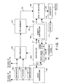
- Fig. 1 is a block diagram which illustrates a schematic construction of an image reading system of this embodiment.
- reference numeral 101 denotes a still video reproducer which performs the following: the rotation of tracks, reproduction of video signals, reading out of image data, erasure of still video floppy disks and so on, on the basis of the control signals inputted from the controller 102.
- the still video reproducer 101 also transfers ID information 12 read out from the still video floppy disk to the controller 102.
- Still video reproduction signals 13 read out from the still video floppy disk are sent to a signal processor 103.
- the signal processor 103 inputs reproduction signals 13 inputted from the still video reproducer 101 and produces brightness signals (Y) 13 and color (R, G and B) signals 15 to 17 by using a well-known matrix circuit by performing demodulation of reproduced signals, signal processing, synchronization of color difference, etc.
- Each of reference numerals 14 to 17 respectively denotes Y (brightness signals), R (red component signals), G (green component signals) and B (blue component signals) produced from still video reproduction signals 13 in the signal processor 103.
- a selector 104 selects and outputs each of the signals 14 to 17 according to a selection signal 18 from the controller 102. The selected signal is made to be a signal 19 and supplied to an A/D converter 105.
- the A/D converter 105 converts the signals 19 from the selector 104 to digital signals.
- Reference numeral 106 denotes a memory controller which outputs memory control signals 22 on the basis of control signals 21 from the controller 102 so that digital image signals 20 which are converted from analog to digital by the A/D converter 105 are stored in a field memory 107 or the field memory 107 is read out.
- the memory controller 106 can also transfer image data stored in the field memory 107 to a computer 110 externally connected through a standard SCSI (small computer systems interface) cable 26 by controlling an SCSI interface section 108 with control signals 25.
- Reference numeral 24 denotes image data read out from the field memory 107 to the SCSI interface section 108; and reference numeral 26 denotes a SCSI cable through which the SCSI interface section 108 is connected to the computer 110.
- the structure of the field memory 107 has a memory capacity of, for example, 640 x 240 x 8 (bits).
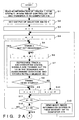
- the controller 102 controls the entire image reading apparatus. It comprises a CPU 201 (microprocessor), ROM 202 in which control programs for the CPU 201 shown in the flowchart in Figs. 2A and 2B and various data are stored and RAM 203 used as a work area for the CPU 201. A track counter n to be described later and an image counter m or the like are provided in the RAM 203.
- Reference numeral 109 denotes an operation panel having various keys by which an instruction that image signals be read out from the still video reproducer 101 is made to the controller 102.
- a control program on the basis of which this process is performed, is stored in the ROM 202. This program is started when a still video floppy disk is exchanged in the still video reproducer 101 or an instruction is given from the operation panel 109 that image signals are read out from the still video floppy disk.
- step S1 ID information of tracks 1 to 50 of a floppy disk is read out by the still video reproducer 101 under the control of the controller 102.
- the ID information 12 is input and stored in the RAM 203 of the controller 102.
- the ID information is transferred through the SCSI interface section 108 to the computer 110 connected via a SCSI cable 26.
- the selection signal 18 supplied to the selector 104 so that the selector 104 is set so as to select and output the brightness signal (Y) 14.
- the process proceeds to step S3 where the track counter n is set at "1", and to step S4 where the image counter m is set at "0".
- step S5 the still video reproducer 101 reads out the track of the video floppy disk indicated by the track counter n, and a check is made to determine whether image data has been stored in the track. If image data has not been stored, the process proceeds to step S9. If it has been, the process proceeds to step S6 where the image counter m is incremented by 1.
- step S7 image signals are read out from the track of the video floppy disk indicated by the track counter n.
- the reproduced signals 13 are sent to the signal processor 103 by the still video reproducer 101.
- Brightness signals (Y) 14 are selected by the selector 104 and output to the A/D converter 105.
- the controller 102 controls the memory controller 106 so that image signals converted to digital by the A/D converter 105 are thinned out to 1/5 in the main scanning and sub-scanning directions and stored in the field memory 107.
- step S8 a check is made to determine whether the image data stored in this track is a frame record.
- the process proceeds to step S9 where only one of the field images is stored in the field memory 107, and the track counter n is incremented by 1.
- the process proceeds to step S10 where the track counter n is incremented by 2.
- step S11 a check is made to determine whether the value of the image counter m has reached "10".
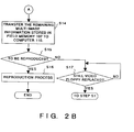
- step S12 a check is made to determine whether the value of the track counter n is equal to "50" or greater. If it is less than "50”, the process returns to step S5 and then to a process for reading out the image data of the next track of the video floppy disk. If it is equal to "50" or greater, the process proceeds to step S14 where the remaining image data stored in the field memory 107 is transferred to the computer 110 via the SCSI interface section 108. In this way, the contents of the field memory 107 are transferred to the computer 110 a maximum of 50 times (when image data has been stored in all of 50 tracks of the still video in field record form).
- step S15 a check is made to determine whether reproduction of an image has been instructed by the computer 110. If reproduction of an image has been instructed, the process proceeds to step S16 where the image data corresponding to the specified ID information is read out by the still video reproducer 101, transferred to the computer 110 via the SCSI interface section 108 and displayed on a monitor 111. On the other hand, if the reproduction has not been instructed, the process proceeds to step S17 where a check is made to determine whether the still video floppy disk of the still video reproducer 101 has been exchanged. When it is exchanged, the process returns to step S1 where the above-described operations are performed.
- the ID information and the image brightness data (Y) transferred to the computer 110 in the above-described way are used as information for the computer 110 to manage floppy disks. That is, the computer 110 creates an index image of all images of a still video floppy disk from image data which have been divided and transferred. Data used to manage still video floppy disks is created by corresponding information, such as track numbers, picture taking year/month/day, frame/field record, etc., obtained from the ID information of the index image, to each of these index images.
- the image reading apparatus of this embodiment transfers each ID information and brightness information (Y) to the computer 110.
- the application software of the computer 110 creates data used to manage floppy disks on the basis of both the ID information and the brightness information (Y).
- the index image as well as track numbers, on the track of which the image is recorded, are displayed on the monitor 111.
- An example of a screen display at this time is shown in Fig. 3.
- Fig. 4 is a flowchart which illustrates an image retrieving process in the computer 110.
- image data binary image
- ID information corresponding to the data are input. Those images are displayed on the monitor 111, as shown in Fig. 3.
- step S23 the system waits for an operator indicates which image is to be retrieved.
- the operator moves a cursor or the like over the image displayed on the monitor 111 by using a mouse 112 connected to the computer 110.
- the process proceeds to step S24 where the ID information of the indicated image is transmitted via the SCSI cable 26 to the image reading apparatus of the embodiment shown in Fig. 1.
- the controller 102 of the image reading apparatus gives an command to the still video reproducer 101 that image data corresponding to the ID information is read out from the still video floppy disk.
- RGB signals 15 to 17 of the image data are sequentially selected by the selector 104 and written in the field memory 107.
- a color image thereof is in turn read out from the field memory 107 and transferred to the computer 110 via the SCSI interface section 108 and the SCSI cable 26.
- the process proceeds from step S25 to step S26 where the image data specified in step S23 is input to the computer 110 as a full color image having the three colors of R, G and B and displayed on the monitor 111 in full color.
- a multi image produced from the ID information of each track and the brightness information recorded in each track is transferred to a computer. Thereafter, the computer displays these multi images as an index and waits for an indication thereof to be made. Images recorded in a video floppy disk are managed and retrieved on the basis of the ID information of each track of the indicated image data. As a consequence, the efficiency of operation and response of the retrieval of the image data stored in the video floppy disk can be increased.
- the transfer of multi images is performed when a video floppy disk is exchanged or by a command from the operation panel
- the present invention is not limited to this case. It goes without saying that it may be performed, for example, by a command from the computer 110.
- a video reproducer 501 may have not only a floppy disk, but also a semiconductor memory or a hard disk in order to store the digital image.
- the video reproducer 501 is a reproducer which reproduces an image data encoded in block and stored in a storage medium compressed by the compressing method, for example, ADCT. (Adaptive Discrete Cosine Transform) set by JPEG (Joint Picture EXpert Group).
- Storage medium in this embodiment can be disk memory, or solid memory such as optical memory, Bloch line memory, semiconductor memory, and the like.
- This video reproducer 501 reproduces a compressed image data from a storage medium and outputs the data to the line 409.
- image data output to this line 409 direct current, e.g. lowest spatial frequency components (DC component) are separated by the separator 401 and input to the multiplexer 407.
- the image data output to the line 409 is output to the decoder 403.
- the decoder 403 decodes the compressed data output to the line 409 and supplies to the decoded data to the multiplexer 407.
- the multiplexer 407 selects an output of either separator 401 or decoder 403 under the control of a controller 502 and outputs to the field memory 107.
- the compressed image data is allowed to an ID data which indicates its compressibility, serial numbers of images, recorded date, comment on the recorded images, and the like. This function will be mentioned later with reference to Fig. 6.
- the ID data is separated by the ID separator 405 and output to the controller 502.
- the reproduced image from the video reproducer 501 is directly output to SCSI interface section 108 via the line 409 without going through the separator 401, the decoder 403 and ID separator 405.
- Fig. 6 there is said ID data in forefront of the image data, and then, data for decode, for example, quantization parameter (to be mentioned later), or Huffmann table is followed. Further, following to this data for decode, DC data (Direct current component) of brightness component Y in which one block data comprising 8 X 8 picture elements has converted by orthogonal transformation, AC data (Alternating current component), DC data (Direct current component) of the color component Cr, Cb, and AC data (Alternating current component) are stored in the block unit.
- DC data Direct current component
- AC data Alternating current component
- DC data Direct current component of the color component Cr, Cb
- AC data Alternating current component
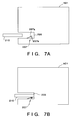
- a check is made to detect whether a storage medium 210 has been exchanged in step S31 on the basis of a state of a switch 207.
- the construction of this switch 207 is shown in Fig. 7A and 7B.
- the switch 207 is having point of contacts, 207a and 207b.
- Fig. 7A when the storage medium 210 is taken out from the attaching section 205 of the video reproducer 501, the point of contact 207a and 207b are separated from each other and a state of the switch 207 becomes "off.”
- Fig. 7A when the storage medium 210 is taken out from the attaching section 205 of the video reproducer 501, the point of contact 207a and 207b are separated from each other and a state of the switch 207 becomes "off.”
- Fig. 7A when the storage medium 210 is taken out from the attaching section 205 of the video reproducer 501, the point of contact 207a and 207b are separated from each other and a state of the switch 207 becomes
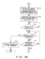
- step S33 a check is made on an output mode.
- Output mode at that time can be set at output mode of the compressed data or output mode of decoded data.
- the process proceeds to step S51 where a check is made to determine whether a mode is set at high speed output mode. If so, the process proceeds to step S53 and the output of the separator 401 is directly output to the computer 110 via SCSI interface section 108; not via the field memory 107.
- the image data can be reproduced at high speed in the computer 110 by that only direct current component and quantization parameter in the image data are sequentially transferred to the computer 110.
- step S51 when a mode is not set at high speed output mode in step S51, the process proceeds to step S55 and the compressed data reproduced from the storage medium 210 is transferred to the computer 110 via the SCSI interface section 108. The process is then proceeded to step S57 where a check is made to determine whether the data is output for predetermined number of screens in advance. When this process has accomplished, the process proceeds to step S47 which will be mentioned later from step S46.
- step S33 in the case of that a mode is not at the output mode of the compressed data, the process proceeds to step S35 where the multiplexer 407 is controlled, and the data from the separator 401 is selected and output to the field memory 107.
- index data that is, reduced image data is stored in the field memory 107 in step S37.
- multi-index images such as shown in Fig. 3 are stored up.
- step S41 from S39 where the index image data is transferred to the computer 110 via the SCSI interface section 108.
- step S43 a command which instructs to read out desired image data from the computer 110 is waited after transfer.
- step S44 the desired image data is read out in the video reproducer 501, decoded in the decoder 403, and stored in the field memory 107. Then, the process proceeds to step S45 where the stored image data is transferred to the computer 110 via the SCSI interface section 108. After this transfer, the process proceeds to step S48 where a check is made to determine if there is any other command from the computer 110. When there is another command, the process proceeds to step S48 where a process corresponding to the command is executed. When no other command is input, the process proceeds to step S49 where a check is made to determine whether a storage medium 210 is exchanged on the basis of a state of the switch 207. When the exchange of the storage medium 210 is confirmed, the process returns to step S33 where the above-mentioned process is performed. While when the exchange is not confirmed, the process returns to step S47 where the processes at step S47 and S49 are repeatedly performed.
- contents of the image data stored in the storage medium 210 is transferred to the computer 110 at high speed and confirmed in short time since exchange of the storage medium 210 is detected and index image data or compressed image date is output to the computer 110.
- the image data can be transferred to the computer 110 simply and at high speed, since only direct current component of the encoded image data is output the the computer 110.
- the controller 502 may determine the function of the computer 110 in advance. It may also be performed according to the input data from the operation panel by manual input.
- the data separated in the separator 401 can be direct current component of only brightness component Y or both brightness component Y and color component Cr, Cb.
- the present invention may be applied to a system comprising a plurality of apparatuses or to a system comprising one apparatus. Needless to say, the present invention can be applied to a case in which programs by which the present invention is performed are supplied to a system or apparatus.
Applications Claiming Priority (2)
| Application Number | Priority Date | Filing Date | Title |
|---|---|---|---|
| JP30849790 | 1990-11-16 | ||
| JP308497/90 | 1990-11-16 |
Publications (2)
| Publication Number | Publication Date |
|---|---|
| EP0486310A2 true EP0486310A2 (en) | 1992-05-20 |
| EP0486310A3 EP0486310A3 (en) | 1993-01-27 |
Family
ID=17981727
Family Applications (1)
| Application Number | Title | Priority Date | Filing Date |
|---|---|---|---|
| EP19910310537 Ceased EP0486310A3 (en) | 1990-11-16 | 1991-11-14 | Method and system for reproducing images |
Country Status (1)
| Country | Link |
|---|---|
| EP (1) | EP0486310A3 (zh) |
Cited By (2)
| Publication number | Priority date | Publication date | Assignee | Title |
|---|---|---|---|---|
| GB2379824A (en) * | 2001-09-11 | 2003-03-19 | Samsung Electronics Co Ltd | Displaying still images on a divided screen |
| FR2849706A1 (fr) * | 2003-01-02 | 2004-07-09 | Thomson Licensing Sa | Procede et dispositif d'acces a des elements multimedia au moyen d'images associees a ces elements |
Citations (11)
| Publication number | Priority date | Publication date | Assignee | Title |
|---|---|---|---|---|
| US4302776A (en) * | 1979-03-22 | 1981-11-24 | Micro Consultants Limited | Digital still picture storage system with size change facility |
| EP0122094A2 (en) * | 1983-04-08 | 1984-10-17 | Ampex Systems Corporation | Electronic still store with high speed sorting and method of operation |
| EP0220991A2 (fr) * | 1985-10-23 | 1987-05-06 | Sony Corporation | Appareil d'enregistrement et/ou de reproduction notamment d'images fixes |
| EP0289944A1 (en) * | 1987-05-01 | 1988-11-09 | Fuji Photo Film Co., Ltd. | Electronic digital still camera for storing component video signals in memory |
| JPH01221076A (ja) * | 1988-02-29 | 1989-09-04 | Casio Comput Co Ltd | 静止画情報再生装置 |
| JPH02105679A (ja) * | 1988-10-14 | 1990-04-18 | Fuji Photo Film Co Ltd | ディジタル画像記録再生装置 |
| EP0382541A2 (en) * | 1989-02-09 | 1990-08-16 | Canon Kabushiki Kaisha | Electronic filing apparatus and method of retrieving image information |
| JPH02208779A (ja) * | 1989-02-09 | 1990-08-20 | Fuji Photo Film Co Ltd | 画像データ再生装置 |
| US4951276A (en) * | 1986-12-03 | 1990-08-21 | Canon Kabushiki Kaisha | Recording apparatus with switch actuated memory storage of recording medium removal or loading and backup power supply for memory |
| DE4032309A1 (de) * | 1989-10-12 | 1991-04-18 | Asahi Optical Co Ltd | Geraet zur magnetischen aufnahme und wiedergabe |
| US5050003A (en) * | 1987-08-11 | 1991-09-17 | Canon Kabushiki Kaisha | Image processing apparatus capable of displaying a plurality of screens |
-
1991
- 1991-11-14 EP EP19910310537 patent/EP0486310A3/en not_active Ceased
Patent Citations (11)
| Publication number | Priority date | Publication date | Assignee | Title |
|---|---|---|---|---|
| US4302776A (en) * | 1979-03-22 | 1981-11-24 | Micro Consultants Limited | Digital still picture storage system with size change facility |
| EP0122094A2 (en) * | 1983-04-08 | 1984-10-17 | Ampex Systems Corporation | Electronic still store with high speed sorting and method of operation |
| EP0220991A2 (fr) * | 1985-10-23 | 1987-05-06 | Sony Corporation | Appareil d'enregistrement et/ou de reproduction notamment d'images fixes |
| US4951276A (en) * | 1986-12-03 | 1990-08-21 | Canon Kabushiki Kaisha | Recording apparatus with switch actuated memory storage of recording medium removal or loading and backup power supply for memory |
| EP0289944A1 (en) * | 1987-05-01 | 1988-11-09 | Fuji Photo Film Co., Ltd. | Electronic digital still camera for storing component video signals in memory |
| US5050003A (en) * | 1987-08-11 | 1991-09-17 | Canon Kabushiki Kaisha | Image processing apparatus capable of displaying a plurality of screens |
| JPH01221076A (ja) * | 1988-02-29 | 1989-09-04 | Casio Comput Co Ltd | 静止画情報再生装置 |
| JPH02105679A (ja) * | 1988-10-14 | 1990-04-18 | Fuji Photo Film Co Ltd | ディジタル画像記録再生装置 |
| EP0382541A2 (en) * | 1989-02-09 | 1990-08-16 | Canon Kabushiki Kaisha | Electronic filing apparatus and method of retrieving image information |
| JPH02208779A (ja) * | 1989-02-09 | 1990-08-20 | Fuji Photo Film Co Ltd | 画像データ再生装置 |
| DE4032309A1 (de) * | 1989-10-12 | 1991-04-18 | Asahi Optical Co Ltd | Geraet zur magnetischen aufnahme und wiedergabe |
Non-Patent Citations (2)
| Title |
|---|
| PATENT ABSTRACTS OF JAPAN vol. 13, no. 539 (E-853)30 November 1989 & JP-A-01 221 076 ( CASIO COMPUT. CO., LTD. ) 4 September 1989 * |
| PATENT ABSTRACTS OF JAPAN vol. 14, no. 320 (E-950)10 July 1990 & JP-A-02 105 679 ( FUJI PHOTO FILM CO., LTD. ) 18 April 1990 * |
Cited By (5)
| Publication number | Priority date | Publication date | Assignee | Title |
|---|---|---|---|---|
| GB2379824A (en) * | 2001-09-11 | 2003-03-19 | Samsung Electronics Co Ltd | Displaying still images on a divided screen |
| GB2379824B (en) * | 2001-09-11 | 2004-01-28 | Samsung Electronics Co Ltd | Optical disk reproducing system for reproducing still pictures and method for reproducing the same |
| NL1021433C2 (nl) * | 2001-09-11 | 2004-04-20 | Samsung Electronics Co Ltd | Afspeelinrichting voor optische disks voor het reproduceren van stilstaande beelden en werkwijze voor het reproduceren van stilstaande beelden. |
| FR2849706A1 (fr) * | 2003-01-02 | 2004-07-09 | Thomson Licensing Sa | Procede et dispositif d'acces a des elements multimedia au moyen d'images associees a ces elements |
| WO2004061710A1 (en) * | 2003-01-02 | 2004-07-22 | Thomson Licensing S.A. | Process and device for access to multimedia elements by means of images associated with these elements |
Also Published As
| Publication number | Publication date |
|---|---|
| EP0486310A3 (en) | 1993-01-27 |
Similar Documents
| Publication | Publication Date | Title |
|---|---|---|
| US8437623B2 (en) | Recording apparatus and method | |
| EP0926878B1 (en) | Digital camera and method which displays a page number of a displayed page | |
| US6072917A (en) | Code sheet and information reproduction apparatus | |
| US6005679A (en) | Image data filing system for quickly retrieving an area of interest of an image from a reduced amount of image data | |
| US6683649B1 (en) | Method and apparatus for creating a multimedia presentation from heterogeneous media objects in a digital imaging device | |
| EP0731469A2 (en) | Video information recording and reproduction apparatus and method as well as video tape | |
| US6549236B2 (en) | Image reproduction apparatus with multiple-screen display mode | |
| JP4533184B2 (ja) | 画像再生装置及び画像再生装置によるインデックス表示方法 | |
| JP3264979B2 (ja) | 画像情報記録再生装置 | |
| JPH10164483A (ja) | 画像データ格納装置 | |
| US7376339B2 (en) | Multi-image reproducing and recording apparatus with appended information | |
| EP0486310A2 (en) | Method and system for reproducing images | |
| EP1152608A2 (en) | Data recording system and recording objective determination device | |
| US7936398B2 (en) | Video signal processing apparatus for converting video signal types | |
| JPS63156476A (ja) | 画像フアイル装置 | |
| US6415097B1 (en) | Image reproducing and storage arrangement with stored image index information | |
| JP2001103421A (ja) | 画像情報記録担体 | |
| KR0163497B1 (ko) | 정지화상화일시스템 | |
| JPH052612A (ja) | 画像再生方法及びシステム | |
| EP0998147A1 (en) | Moving picture coding/decoding apparatus generating additional indexing information | |
| US20090297119A1 (en) | Information recording and reproducing apparatus | |
| JP3197290B2 (ja) | データ転送装置 | |
| JP3196247B2 (ja) | 画像再生装置 | |
| JPH10164557A (ja) | 記録媒体の再生画像におけるメニュー画面作成方法及びそのサーチ方法 | |
| EP0435169B1 (en) | Image display system and method of displaying an image therewith |
Legal Events
| Date | Code | Title | Description |
|---|---|---|---|
| PUAI | Public reference made under article 153(3) epc to a published international application that has entered the european phase |
Free format text: ORIGINAL CODE: 0009012 |
|
| AK | Designated contracting states |
Kind code of ref document: A2 Designated state(s): DE FR GB |
|
| PUAL | Search report despatched |
Free format text: ORIGINAL CODE: 0009013 |
|
| AK | Designated contracting states |
Kind code of ref document: A3 Designated state(s): DE FR GB |
|
| 17P | Request for examination filed |
Effective date: 19930609 |
|
| 17Q | First examination report despatched |
Effective date: 19950227 |
|
| STAA | Information on the status of an ep patent application or granted ep patent |
Free format text: STATUS: THE APPLICATION HAS BEEN REFUSED |
|
| 18R | Application refused |
Effective date: 20000205 |