EP0801277A2 - Building with outer wall using solar energy - Google Patents
Building with outer wall using solar energy Download PDFInfo
- Publication number
- EP0801277A2 EP0801277A2 EP97101784A EP97101784A EP0801277A2 EP 0801277 A2 EP0801277 A2 EP 0801277A2 EP 97101784 A EP97101784 A EP 97101784A EP 97101784 A EP97101784 A EP 97101784A EP 0801277 A2 EP0801277 A2 EP 0801277A2
- Authority
- EP
- European Patent Office
- Prior art keywords
- wall
- building
- building according
- heating
- interior
- Prior art date
- Legal status (The legal status is an assumption and is not a legal conclusion. Google has not performed a legal analysis and makes no representation as to the accuracy of the status listed.)
- Withdrawn
Links
Images


Classifications
-
- F—MECHANICAL ENGINEERING; LIGHTING; HEATING; WEAPONS; BLASTING
- F24—HEATING; RANGES; VENTILATING
- F24D—DOMESTIC- OR SPACE-HEATING SYSTEMS, e.g. CENTRAL HEATING SYSTEMS; DOMESTIC HOT-WATER SUPPLY SYSTEMS; ELEMENTS OR COMPONENTS THEREFOR
- F24D11/00—Central heating systems using heat accumulated in storage masses
- F24D11/002—Central heating systems using heat accumulated in storage masses water heating system
- F24D11/003—Central heating systems using heat accumulated in storage masses water heating system combined with solar energy
-
- F—MECHANICAL ENGINEERING; LIGHTING; HEATING; WEAPONS; BLASTING
- F24—HEATING; RANGES; VENTILATING
- F24S—SOLAR HEAT COLLECTORS; SOLAR HEAT SYSTEMS
- F24S20/00—Solar heat collectors specially adapted for particular uses or environments
- F24S20/60—Solar heat collectors integrated in fixed constructions, e.g. in buildings
- F24S20/61—Passive solar heat collectors, e.g. operated without external energy source
-
- F—MECHANICAL ENGINEERING; LIGHTING; HEATING; WEAPONS; BLASTING
- F24—HEATING; RANGES; VENTILATING
- F24S—SOLAR HEAT COLLECTORS; SOLAR HEAT SYSTEMS
- F24S20/00—Solar heat collectors specially adapted for particular uses or environments
- F24S20/60—Solar heat collectors integrated in fixed constructions, e.g. in buildings
- F24S20/66—Solar heat collectors integrated in fixed constructions, e.g. in buildings in the form of facade constructions, e.g. wall constructions
-
- Y—GENERAL TAGGING OF NEW TECHNOLOGICAL DEVELOPMENTS; GENERAL TAGGING OF CROSS-SECTIONAL TECHNOLOGIES SPANNING OVER SEVERAL SECTIONS OF THE IPC; TECHNICAL SUBJECTS COVERED BY FORMER USPC CROSS-REFERENCE ART COLLECTIONS [XRACs] AND DIGESTS
- Y02—TECHNOLOGIES OR APPLICATIONS FOR MITIGATION OR ADAPTATION AGAINST CLIMATE CHANGE
- Y02B—CLIMATE CHANGE MITIGATION TECHNOLOGIES RELATED TO BUILDINGS, e.g. HOUSING, HOUSE APPLIANCES OR RELATED END-USER APPLICATIONS
- Y02B10/00—Integration of renewable energy sources in buildings
- Y02B10/20—Solar thermal
-
- Y—GENERAL TAGGING OF NEW TECHNOLOGICAL DEVELOPMENTS; GENERAL TAGGING OF CROSS-SECTIONAL TECHNOLOGIES SPANNING OVER SEVERAL SECTIONS OF THE IPC; TECHNICAL SUBJECTS COVERED BY FORMER USPC CROSS-REFERENCE ART COLLECTIONS [XRACs] AND DIGESTS
- Y02—TECHNOLOGIES OR APPLICATIONS FOR MITIGATION OR ADAPTATION AGAINST CLIMATE CHANGE
- Y02E—REDUCTION OF GREENHOUSE GAS [GHG] EMISSIONS, RELATED TO ENERGY GENERATION, TRANSMISSION OR DISTRIBUTION
- Y02E10/00—Energy generation through renewable energy sources
- Y02E10/40—Solar thermal energy, e.g. solar towers
- Y02E10/46—Conversion of thermal power into mechanical power, e.g. Rankine, Stirling or solar thermal engines
Definitions
- the invention relates to a building with parapet and wall areas which, for the use of solar energy, has an absorption layer that absorbs solar radiation between a wall shell on the inside of the building and a wall shell that is permeable to solar radiation and the inner wall surface results in heat flow flowing into the building interior.
- the invention has for its object to further develop the arrangement in a building with an outer wall of the type mentioned in such a way that the consciously accepted reduction in the use of solar energy is as small as possible.
- At least one heating element provided for space heating and containing a heat storage medium is arranged on the inside of the building on the outside wall with a clear distance in front of the inside wall surface, that a convection space is formed between the inner wall surface and the heating element and can be flowed through by the air of the interior of the building, and that adjustable flow devices are provided with which the air flow through the convection space can be set and also shut off.
- the heating element and the cladding serve to shield part of the inner wall surface and thereby reduce the heat radiation of this part of the inner wall surface into the interior of the building, so that a correspondingly higher value is permitted for the maximum temperature on the inner wall surface without this Feeling of comfort in the interior of the building is impaired.
- This permissible higher maximum temperature on the inner wall surface means better use of the solar energy supply.
- the setting of the air flow through the convection space makes it possible to influence the heat transfer from the inner wall surface in the direction of the building interior by reducing the air flow by reducing the heat transfer.
- the air flow is throttled or completely blocked, so that excessive temperatures in the interior of the building are avoided, while in winter with low outside temperatures and / or low solar energy supply, a stronger air flow causes the heat flowing through the wall shell inside the building correspondingly more complete on the inner wall surface can record and transfer into the building interior.
- the storage medium in the radiator enables the heat from the convection room to be stored at times when the amount of solar energy is high, when the air flow through the convection room is largely restricted or completely blocked, and the delayed release of the stored heat when the solar energy supply becomes smaller or completely disappears, such as at night, for example. if the heat can be extracted from the storage medium, in addition to being radiated directly into the interior, in particular also by the air flow which then flows again more strongly in the convection space.
- the adjustment of the flow devices with which the air flow through the convection space can be adjusted generally takes place in dependence on the prevailing thermal conditions outside and inside the building and on the solar energy supply. In the simplest and roughest cases, this adjustment can be made by hand in such a way that the air flow through the convection space is throttled or completely blocked in summer, but can flow in winter.
- An embodiment of the invention which is much better than and therefore preferred, is characterized in that the flow devices have actuators for their adjustment and the actuators can be controlled outside and / or inside the building depending on selected climate values.
- the outside temperature and the solar energy supply on the one hand and the inside temperature can be used as climate values for this control serve on the other hand in the building interior and / or the inside surface temperature, for which purpose these sensors that measure climate values can be provided.
- a further preferred embodiment of the invention is characterized in that the cladding has a top wall that overlaps the convection space and adjoins the inner wall surface of the outer wall with outlet openings for the air flowing through the convection space, and that the adjustable flow devices of closure members, such as sliders, flaps or the like, are formed for the outlet openings.
- the cladding preferably also has a front wall which is essentially parallel to the inner wall surface and which adjoins the top wall at the top and closes the convection space below the top wall from the interior of the building. The front wall can completely cover the radiator towards the interior of the building, so that the radiator as a whole is located within the convection room.
- the front wall has a recess receiving the radiator, in which the radiator with its wall facing the interior of the building is essentially flush with the outer surface of the front wall and with its upper edge and its two lateral edges close to the associated one Edges of the recess connects.
- the cladding can then not hinder the heat radiation from the radiator into the building interior during the heating season.
- the air supply to the convection room can be done in different ways.
- the radiator can be raised; however, there is also the possibility that the front wall in the floor area of the building interior has inlet openings for the entry of the air into the convection room.
- the air flow can result solely from gravitational forces; but a blower driving it can also be provided.
- the top wall and / or the front wall of the cladding preferably extends continuously over all heating elements, so that, for example, the entire parapet area of the outer wall can be covered on the inside of the building by the cladding or heating element.
- the cladding can have a thermal barrier coating on the inner surface facing the convection space, so that a high air temperature in the convection space, for example with little or no air flow, in particular with a high solar supply, cannot generate undesirable high temperatures on the surface of the cladding facing the building interior.
- a high air temperature in the convection space for example with little or no air flow, in particular with a high solar supply
- the wall inner surface is faced by a closed surface of the heating element as far as possible and that both surfaces enclose the convection space between them.
- the inner wall surface and the Cladding surface to be adapted to each other with respect to their radiation emissivity.
- the heater body will be a radiator or convector connected to a heater water circuit, the heater water filling the heater body forming the heat storage means. Then it can be particularly advantageous to make the arrangement so that the heating water can be circulated between radiators that are located on an outer wall with excess heat, on the one hand, and radiators that are located on an outer wall with heat deficit. Then, especially in transition seasons, the excess solar energy available on the south side of the building can be transferred to the radiators on the north side of the building by storing it in the water (especially when the air flow is blocked or throttled), thereby compensating for the energy deficit there. It can also be provided that a heat exchanger is arranged in the circuit of the circulating heating water, through which the heat can be supplied to a service water reservoir.
- the heating element is formed by one or more plates spaced apart and parallel to each other.
- the outer wall 1 shows a part of a building with a parapet area 1 and on the inside of the parapet area for space heating provided with water-filled heating elements 2, which are arranged at a free distance d in front of the inner wall surface 3.
- a floor ceiling of the building is designated 4.
- the radiator 2 are supported with feet 5.
- the outer wall 1 has a structure intended for the use of solar energy, the details of which are only shown in the middle wall element of the part of the outer wall 1 shown.
- an absorption layer 9 is arranged which absorbs the solar radiation from the air space 8.
- the heat energy obtained in the absorption layer 9 from the solar radiation results in a heat flow directed outwards on the one hand, and a heat flow flowing through the wall shell 6 on the inside of the building and the wall surface 3 into the interior of the building (in each case on the right side of the outer wall 1 in the drawing).
- a cladding 10 is provided on the inside of the building, through which a convection space 11, which is located between the inner wall surface 3 and the heating element 2 and through which the air of the interior of the building can flow, is formed.
- the strength of the air flow flowing through the convection chamber 10 can be adjusted by means of adjustable flow devices.
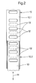
- the cladding 10 has a top wall 10.1, which overlaps the convection chamber 11 and adjoins the wall inner surface 3 of the outer wall 1, with outlet openings 12 for the air flowing through the convection chamber 11.
- the flow devices adjusting the air flow are formed by suitable closure members 13 for these outlet openings 12.
- Such closure members 13 can be adjustable slides, as in FIGS. 1, 2 and 3, or flaps, as in FIG. 4, the closure members 13 being pulled out in the drawing in their position closing the outlet openings 12 and in their outlet openings 12 completely releasing position 13 'are shown in dashed lines.
- the closure members 13 are adjusted in each case in the direction of the double arrows 14.
- the cladding 10 has a front wall 10.2 which is essentially parallel to the inner wall surface 3 and which adjoins the top wall 10.1 above and below the top wall 10.1 the convection space 11 towards the building interior down to openings 15 provided in the floor area of the building interior for the entry of air into the convection chamber 11.
- the top wall 10.1 and the front wall 10.2 extend continuously over all radiators 2.
- the front wall 10.2 can have a recess 16 for each radiator 2 in which the radiator 2 with its Building interior facing wall 17 is flush with the outer surface of the front wall 10.2 and with its upper edge and its two lateral edges closely adjoins the associated edges of the recess 16.
- FIG. 1 there is also the possibility shown in FIG.
- the closure members 13 forming the flow devices have actuators, not shown in detail, which can be controlled outside and / or inside the building depending on selected climate values.
- climate values can be the outside temperature and the solar energy supply on the one hand and the inside temperature in the building interior and / or the inside surface temperature on the other. Sensors can be provided to record these climate values be, which are also not shown in the drawing.
- the lining 10 can carry a thermal insulation layer 18 on the inner surface facing the convection space 11, which is indicated in FIGS. 3 and 4 only by a thicker stroke width.
- the heating element 2 faces the inner wall surface 3 of the outer wall with a jacket surface 19 that is as closed as possible.
- the convection space 11 is located between these two surfaces 3, 19, so that the air flowing through the convection space 11 can sweep along both surfaces 3, 19.
- the inner wall surface 3 and the outer surface 19 can be adapted to one another with regard to their radiation emissivity. As a result, it can easily be achieved in this way that the heating elements 2, in conjunction with the cladding 10, considerably reduce the heat radiation from the inner wall surface 3, insofar as the latter lies within the convection space 11.
- the heating elements 2 are connected to a heating water circuit, not shown in detail, and are designed as a radiator or convector, which, depending on the individual configuration, may already have the above-mentioned closed jacket surface 19.
- the heating water filling the heating elements 2 forms a heat storage means which can absorb and store heat from the convection space 11, in particular when the outlet openings 12 are more or less closed and thus the air flow through the convection space 11 is throttled or blocked accordingly. So that radiant heat reaching the jacket surface 19 from the inner wall surface 3 can be supplied for storage in the heating water, the jacket surface 19 must, as is the case with convectors anyway, be in good heat conduction connection with the parts of the heater body carrying the heating water.
- the heating body 2 can also be formed by several, spaced and parallel plates.
Abstract
Description
Die Erfindung betrifft ein Gebäude mit Brüstungs- und Wandbereichen, die zur Nutzung von Solarenergie zwischen einer gebäudeinnenseitigen Wandschale und einer für die Solarstrahlung durchlässigen, gebäudeaußenseitigen Wandschale eine Solarstrahlung aufnehmende Absorptionsschicht aufweist, wobei die in der Absorptionsschicht aus der Solarstrahlung gewonnene Wärmeenergie einen durch die gebäudeinnenseitige Wandschale und die Wandinnenoberfläche in den Gebäudeinnenraum fließenden Wärmestrom ergibt.The invention relates to a building with parapet and wall areas which, for the use of solar energy, has an absorption layer that absorbs solar radiation between a wall shell on the inside of the building and a wall shell that is permeable to solar radiation and the inner wall surface results in heat flow flowing into the building interior.
Gebäude mit einer derartig aufgebauten Außenwand sind aus WO 95/10 741 bekannt. Für die am Standort des Gebäudes zu erwartende größtmögliche Sonneneinstrahlung sind der Gesamtenergiedurchlaßgrad, die Wärmedurchgangswiderstände der beiden Wandschalen sowie der Absorptionsgrad an der Absorptionsschicht so aufeinander abgestimmt, daß sowohl ein maximaler Temperaturwert an der Absorptionsschicht als auch ein maximaler Temperaturwert an der Wandinnenoberfläche nicht überschritten wird. Durch die Temperaturbegrenzung an der Absorptionsschicht wird erreicht, daß Überhitzungen im Wandaufbau vermieden werden, während die Temperaturbegrenzung an der Wandinnenoberfläche dafür sorgt, daß die Temperatur an der Wandinnenoberfläche wie auch der an der Wandinnenoberfläche zur Luft im Gebäudeinnenraum hin auftretende Temperatursprung selbst bei maximaler Sonneneinstrahlung in Bereichen liegt, die von im Innenraum sich aufhaltenden Personen noch als behaglich empfunden werden. Dabei wird bewußt eine Verringerung der Solarenergienutzung während einer verminderten Sonneneinstrahlungsperiode in Kauf genommen.Buildings with an outer wall constructed in this way are known from WO 95/10 741. For the largest possible to be expected at the location of the building The total energy transmittance, the thermal resistance of the two wall shells and the degree of absorption at the absorption layer are matched to one another in such a way that both a maximum temperature value on the absorption layer and a maximum temperature value on the inner wall surface are not exceeded. The temperature limitation on the absorption layer ensures that overheating in the wall structure is avoided, while the temperature limitation on the inner wall surface ensures that the temperature on the inner wall surface as well as the temperature jump occurring on the inner wall surface towards the air in the building interior, even with maximum solar radiation in areas lies, which are still perceived as comfortable by people in the interior. A reduction in the use of solar energy during a reduced solar radiation period is consciously accepted.
Der Erfindung liegt die Aufgabe zugrunde, bei einem Gebäude mit einer Außenwand der eingangs genannten Art die Anordnung so weiter auszubilden, daß die bewußt in Kauf genommene Verringerung der Solarenergienutzung möglichst klein ist.The invention has for its object to further develop the arrangement in a building with an outer wall of the type mentioned in such a way that the consciously accepted reduction in the use of solar energy is as small as possible.
Diese Aufgabe wird bei einem Gebäude mit den eingangs genannten Merkmalen erfindungsgemäß dadurch gelöst, daß mindestens ein für die Raumheizung vorgesehener, ein Wärmespeichermittel enthaltender Heizungskörper auf der Gebäudeinnenseite der Außenwand mit freiem Abstand vor der Wandinnenoberfläche angeordnet ist, daß durch eine Verkleidung ein zwischen der Wandinnenoberfläche und dem Heizungskörper gelegener, von der Luft des Gebäudeinnenraums durchströmbarer Konvektionsraum gebildet ist, und daß verstellbare Strömungseinrichtungen vorgesehen sind, mit welchen der Luftstrom durch den Konvektionsraum einstellbar und auch absperrbar ist.This object is achieved according to the invention in a building with the features mentioned at the outset in that at least one heating element provided for space heating and containing a heat storage medium is arranged on the inside of the building on the outside wall with a clear distance in front of the inside wall surface, that a convection space is formed between the inner wall surface and the heating element and can be flowed through by the air of the interior of the building, and that adjustable flow devices are provided with which the air flow through the convection space can be set and also shut off.
Bei dieser Anordnung dienen der Heizungskörper und die Verkleidung dazu, einen Teil der Wandinnenoberfläche abzuschirmen und dadurch die Wärmeabstrahlung dieses Teils der Wandinnenoberfläche in den Gebäudeinnenraum hinein zu reduzieren, so daß für die maximale Temperatur an der Wandinnenoberfläche ein entsprechender höherer Wert zulässig wird, ohne daß das Gefühl der Behaglichkeit sich im Gebäudeinnenraum aufhaltender Personen beeinträchtigt wird. Diese zulässige höhere Maximaltemperatur an der Wandinnenoberfläche bedeutet eine bessere Nutzung des Solarenergieangebots. Dabei ermöglicht es die Einstellung des Luftstroms durch den Konvektionsraum, den Wärmeübergang von der Wandinnenoberfläche in Richtung zum Gebäudeinnenraum hin nach Wunsch zu beeinflussen, indem eine Drosselung des Luftstroms den Wärmeübergang verringert. Im Sommer bei entsprechend hohen Außentemperaturen und/oder hohem Solarenergieangebot wird der Luftstrom gedrosselt oder ganz gesperrt, so daß zu hohe Temperaturen im Gebäudeinnenraum vermieden werden, während im Winter bei niedrigen Außentemperaturen und/oder niedrigem Solarenergieangebot ein stärkerer Luftstrom die durch die gebäudeinnenseitige Wandschale fließende Wärme an der Wandinnenoberfläche entsprechend vollständiger aufnehmen und in den Gebäudeinnenraum übertragen kann. Das im Heizungskörper vorhandene Speichermittel ermöglicht eine Speicherung der Wärme aus dem Konvektionsraum zu Zeiten hohen Solarenergieangebots, wenn der Luftstrom durch den Konvektionsraum weitgehend gedrosselt oder ganz gesperrt ist, und die verzögerte Abgabe der gespeicherten Wärme bei kleiner werdendem oder völlig verschwindendem Solarenergieangebot, wie beispielsweise nachts, wenn der Wärmeentzug aus dem Speichermittel außer durch direkte Abstrahlung in den Innenraum insbesondere auch durch den dann wieder im Konvektionsraum stärker fließenden Luftstrom erfolgen kann.In this arrangement, the heating element and the cladding serve to shield part of the inner wall surface and thereby reduce the heat radiation of this part of the inner wall surface into the interior of the building, so that a correspondingly higher value is permitted for the maximum temperature on the inner wall surface without this Feeling of comfort in the interior of the building is impaired. This permissible higher maximum temperature on the inner wall surface means better use of the solar energy supply. The setting of the air flow through the convection space makes it possible to influence the heat transfer from the inner wall surface in the direction of the building interior by reducing the air flow by reducing the heat transfer. In summer with correspondingly high outside temperatures and / or high solar energy supply, the air flow is throttled or completely blocked, so that excessive temperatures in the interior of the building are avoided, while in winter with low outside temperatures and / or low solar energy supply, a stronger air flow causes the heat flowing through the wall shell inside the building correspondingly more complete on the inner wall surface can record and transfer into the building interior. The storage medium in the radiator enables the heat from the convection room to be stored at times when the amount of solar energy is high, when the air flow through the convection room is largely restricted or completely blocked, and the delayed release of the stored heat when the solar energy supply becomes smaller or completely disappears, such as at night, for example. if the heat can be extracted from the storage medium, in addition to being radiated directly into the interior, in particular also by the air flow which then flows again more strongly in the convection space.
Die Verstellung der Strömungseinrichtungen, mit welchen der Luftstrom durch den Konvektionsraum einstellbar ist, erfolgt allgemein in Abhängigkeit von den jeweils herrschenden thermischen Verhältnissen außerhalb und innerhalb des Gebäudes und vom Solarenergieangebot. Diese Verstellung kann im einfachsten und gröbsten Fall von Hand derart erfolgen, daß im Sommer der Luftstrom durch den Konvektionsraum gedrosselt oder ganz gesperrt ist, im Winter dagegen fließen kann. Eine dem gegenüber wesentlich bessere und daher bevorzugte Ausführungsform der Erfindung ist allerdings dadurch gekennzeichnet, daß die Strömungseinrichtungen zu ihrer Verstellung Stellglieder besitzen und die Stellglieder abhängig von ausgewählten Klimawerten außerhalb und/oder innerhalb des Gebäudes steuerbar sind. Als Klimawerte für diese Steuerung können insbesondere die Außentemperatur und das Solarenergieangebot einerseits und die Innentemperatur im Gebäudeinnenraum und/oder die Innenoberflächentemperatur andererseits dienen, wozu diese Klimawerte erfassende Fühler vorgesehen sein können.The adjustment of the flow devices with which the air flow through the convection space can be adjusted generally takes place in dependence on the prevailing thermal conditions outside and inside the building and on the solar energy supply. In the simplest and roughest cases, this adjustment can be made by hand in such a way that the air flow through the convection space is throttled or completely blocked in summer, but can flow in winter. An embodiment of the invention, which is much better than and therefore preferred, is characterized in that the flow devices have actuators for their adjustment and the actuators can be controlled outside and / or inside the building depending on selected climate values. In particular, the outside temperature and the solar energy supply on the one hand and the inside temperature can be used as climate values for this control serve on the other hand in the building interior and / or the inside surface temperature, for which purpose these sensors that measure climate values can be provided.
Eine weiter bevorzugte Ausführungsform der Erfindung ist dadurch gekennzeichnet, daß die Verkleidung eine den Konvektionsraum oben übergreifende, an die Wandinnenoberfläche der Außenwand anschließende Deckwand mit Austrittsöffnungen für die den Konvektionsraum durchströmende Luft aufweist und daß die verstellbaren Strömungseinrichtungen von Verschlußgliedern, wie Schiebern, Klappen oder dergleichen, für die Austrittsöffnungen gebildet sind. Vorzugsweise besitzt die Verkleidung weiter eine zur Wandinnenoberfläche im wesentlichen parallele Frontwand, die oben an die Deckwand anschließt und unterhalb der Deckwand den Konvektionsraum gegen den Gebäudeinnenraum hin abschließt. Dabei kann die Frontwand den Heizungskörper zum Gebäudeinnenraum hin vollständig abdecken, der Heizungskörper sich somit insgesamt innerhalb des Konvektionsraums befinden. Es besteht aber auch die Möglichkeit, daß die Frontwand eine den Heizungskörper aufnehmende Aussparung aufweist, in der der Heizungskörper mit seiner dem Gebäudeinnenraum zugekehrten Wandung im wesentlichen bündig mit der Außenfläche der Frontwand abschließt und mit seinem oberen Rand sowie seinen beiden seitlichen Rändern dicht an die zugeordneten Ränder der Aussparung anschließt. Die Verkleidung kann dann während der Heizperiode die Wärmeabstrahlung des Heizungskörpers in den Gebäudeinnenraum hinein nicht behindern.A further preferred embodiment of the invention is characterized in that the cladding has a top wall that overlaps the convection space and adjoins the inner wall surface of the outer wall with outlet openings for the air flowing through the convection space, and that the adjustable flow devices of closure members, such as sliders, flaps or the like, are formed for the outlet openings. The cladding preferably also has a front wall which is essentially parallel to the inner wall surface and which adjoins the top wall at the top and closes the convection space below the top wall from the interior of the building. The front wall can completely cover the radiator towards the interior of the building, so that the radiator as a whole is located within the convection room. But there is also the possibility that the front wall has a recess receiving the radiator, in which the radiator with its wall facing the interior of the building is essentially flush with the outer surface of the front wall and with its upper edge and its two lateral edges close to the associated one Edges of the recess connects. The cladding can then not hinder the heat radiation from the radiator into the building interior during the heating season.
Die Luftzufuhr in den Konvektionsraum kann auf verschiedene Weise erfolgen. Im einfachsten Fall kann der Heizkörper aufgeständert sein; es besteht jedoch auch die Möglichkeit, daß für den Eintritt der Luft in den Konvektionsraum die Frontwand im Fußbodenbereich des Gebäudeinnenraums Eintrittsöffnungen aufweist. Dabei kann sich der Luftstrom allein aus Gravitationskräften ergeben; es kann aber auch ein ihn antreibendes Gebläse vorgesehen sein.The air supply to the convection room can be done in different ways. In the simplest case, the radiator can be raised; however, there is also the possibility that the front wall in the floor area of the building interior has inlet openings for the entry of the air into the convection room. The air flow can result solely from gravitational forces; but a blower driving it can also be provided.
Sind mehrere Heizungskörper vor der Wandinnenoberfläche nebeneinander angeordnet, erstreckt sich vorzugsweise die Deckwand und/oder die Frontwand der Verkleidung durchlaufend über alle Heizungskörper, so daß beispielsweise der gesamte Brüstungsbereich der Außenwand gebäudeinnenseitig durch die Verkleidung bzw. Heizungskörper überdeckt sein kann.If several heating elements are arranged next to each other in front of the inner wall surface, the top wall and / or the front wall of the cladding preferably extends continuously over all heating elements, so that, for example, the entire parapet area of the outer wall can be covered on the inside of the building by the cladding or heating element.
Die Verkleidung kann auf der dem Konvektionsraum zugewandten Innenoberfläche eine Wärmedämmschicht aufweisen, damit eine hohe Lufttemperatur im Konvektionsraum, bei beispielsweise geringem oder fehlendem Luftstrom, insbesondere bei hohem Solarangebot, an der dem Gebäudeinnenraum zugewandten Oberfläche der Verkleidung keine unerwünschten hohen Temperaturen erzeugen kann. Auch empfiehlt es sich im Hinblick auf die Reduzierung der Wärmeabstrahlung der Wandinnenoberfläche, daß der Wandinnenoberfläche eine möglichst geschlossene Manteloberfläche des Heizungskörpers gegenübersteht und beide Oberflächen zwischen sich den Konvektionsraum einschließen. Dabei können die Wandinnenoberfläche und die Manteloberfläche bezüglich ihrer Strahlungsemissivität einander angepaßt sein.The cladding can have a thermal barrier coating on the inner surface facing the convection space, so that a high air temperature in the convection space, for example with little or no air flow, in particular with a high solar supply, cannot generate undesirable high temperatures on the surface of the cladding facing the building interior. With regard to the reduction of the heat radiation of the inner wall surface, it is also recommended that the wall inner surface is faced by a closed surface of the heating element as far as possible and that both surfaces enclose the convection space between them. The inner wall surface and the Cladding surface to be adapted to each other with respect to their radiation emissivity.
Im allgemeinen wird der Heizungskörper ein an einen Heizungswasserumlauf angeschlossener Radiator oder Konvektor sein, wobei das den Heizungskörper füllende Heizungswasser das Wärmespeichermittel bildet. Dann kann es von besonderem Vorteil sein, die Anordnung so zu treffen, daß das Heizungswasser zwischen Heizkörpern, die sich an einer Außenwand mit Wärmeüberschuß befinden, einerseits und Heizkörpern, die sich an einer Außenwand mit Wärmedefizit befinden, andererseits umwälzbar ist. Dann kann insbesondere in Übergangsjahreszeiten das auf der Gebäudesüdseite im Überschuß vorhandene Solarenergieangebot durch Speicherung im Wasser der dortigen Heizungskörper (bei insbesondere gesperrtem oder gedrosseltem Luftstrom) in die Heizungskörper auf der Gebäudenordseite übertragen und so das dort bestehende Energiedefizit ausgeglichen werden. Es kann dabei auch vorgesehen sein, daß in dem Kreislauf des umwälzbaren Heizungswassers ein Wärmetauscher angeordnet ist, durch den die Wärme einem Brauchwasserreservoir zuführbar ist.In general, the heater body will be a radiator or convector connected to a heater water circuit, the heater water filling the heater body forming the heat storage means. Then it can be particularly advantageous to make the arrangement so that the heating water can be circulated between radiators that are located on an outer wall with excess heat, on the one hand, and radiators that are located on an outer wall with heat deficit. Then, especially in transition seasons, the excess solar energy available on the south side of the building can be transferred to the radiators on the north side of the building by storing it in the water (especially when the air flow is blocked or throttled), thereby compensating for the energy deficit there. It can also be provided that a heat exchanger is arranged in the circuit of the circulating heating water, through which the heat can be supplied to a service water reservoir.
Schließlich besteht im Rahmen der Erfindung die Möglichkeit, daß der Heizungskörper von einer oder mehreren, mit Abstand und parallel zueinander angeordneten Platten gebildet ist.Finally, there is the possibility within the scope of the invention that the heating element is formed by one or more plates spaced apart and parallel to each other.
Im folgenden wird die Erfindung an in der Zeichnung dargestellten Ausführungsbeispielen näher erläutert; es zeigen:
- Fig. 1
- einen gemäß der Erfindung ausgebildeten Gebäudeteil, teils im Querschnitt, teils in einer Schrägansicht vom Gebäudeinnenraum her gesehen,
- Fig. 2
- eine Draufsicht auf die Deckwand der Verkleidung in Fig. 1 in Richtung des dort eingetragenen Pfeils II,
- Fig. 3
- einen Teil des Querschnitts aus Fig. 1 in vergrößerter Darstellung, und
- Fig. 4
- den Gegenstand der Fig. 3 in einer anderen Ausführungsform,
- Fig. 5
- unterschiedliche Gestaltungsmöglichkeiten des Heizkörpers.
- Fig. 1
- a part of the building designed according to the invention, partly in cross section, partly in an oblique view from the interior of the building,
- Fig. 2
- 2 shows a plan view of the top wall of the lining in FIG. 1 in the direction of the arrow II entered there,
- Fig. 3
- a part of the cross section of FIG. 1 in an enlarged view, and
- Fig. 4
- 3 in another embodiment,
- Fig. 5
- different design options for the radiator.
Die Fig. 1 zeigt einen Teil eines Gebäudes mit einem Brüstungsbereich 1 und auf der Gebäudeinnenseite des Brüstungsbereichs für die Raumheizung vorgesehenen, mit Wasser gefüllten Heizungskörpern 2, die mit freiem Abstand d vor der Wandinnenoberfläche 3 angeordnet sind. Eine Geschoßdecke des Gebäudes ist mit 4 bezeichnet. Auf dieser Geschoßdecke 4 sind die Heizungskörper 2 mit Füßen 5 abgestützt. Die Außenwand 1 besitzt einen zur Nutzung von Solarenergie bestimmten Aufbau, der bezüglich seiner Einzelheiten nur im mitteleren Wandelement des gezeigten Teils der Außenwand 1 dargestellt ist. Zwischen einer als Wärmedämmschicht ausgebildeten gebäudeinnenseitigen Wandschale 6 und einer für Solarstrahlung durchlässigen, gebäudeaußenseitigen Wandschale 7, die als Wärmedämmschicht einen Luftraum 8 enthält, ist eine die Solarstrahlung aus dem Luftraum 8 aufnehmende Absorptionsschicht 9 angeordnet. Die in der Absorptionsschicht 9 aus der Solarstrahlung gewonnene Wärmeenergie ergibt einen einerseits nach außen gerichteten Wärmestrom, andererseits einen durch die gebäudeinnenseitige Wandschale 6 und die Wandinnenoberfläche 3 in den Gebäudeinnenraum (jeweils auf der in Zeichnung rechten Seite der Außenwand 1) fließenden Wärmestrom. Auf der Gebäudeinnenseite ist eine Verkleidung 10 vorgesehen, durch die ein zwischen der Wandinnenoberfläche 3 und dem Heizungskörper 2 gelegener, von der Luft des Gebäudeinnenraums durchströmbarer Konvektionsraum 11 gebildet ist. Der den Konvektionsraum 10 durchfließende Luftstrom ist hinsichtlich seiner Stärke durch verstellbare Strömungseinrichtungen einstellbar. Im einzelnen besitzt die Verkleidung 10 eine den Konvektionsraum 11 oben übergreifende, an die Wandinnenoberfläche 3 der Außenwand 1 anschließende Deckwand 10.1 mit Austrittsöffnungen 12 für die den Konvektionsraum 11 durchströmende Luft. Die den Luftstrom einstellenden Strömungseinrichtungen sind von geeigneten Verschlußgliedern 13 für diese Austrittsöffnungen 12 gebildet. Solche Verschlußglieder 13 können verstellbare Schieber, wie in den Fig. 1, 2 und 3, oder Klappen, wie in Fig. 4 sein, wobei die Verschlußglieder 13 in der Zeichnung in ihrer die Austrittsöffnungen 12 schließenden Stellung ausgezogen, in ihrer die Austrittsöffnungen 12 völlig freigebenden Stellung 13' gestrichelt dargestellt sind. Die Verstellung der Verschlußglieder 13 erfolgt jeweils in Richtung der Doppelpfeile 14. Weiter besitzt die Verkleidung 10 eine zur Wandinnenoberfläche 3 im wesentlichen parallele Frontwand 10.2, die oben an die Deckwand 10.1 anschließt und unterhalb der Deckwand 10.1 den Konvektionsraum 11 gegen den Gebäudeinnenraum hin bis auf im Fußbodenbereich des Gebäudeinnenraums vorgesehene Öffnungen 15 für den Eintritt der Luft in den Konvektionsraum 11 abschließt. Die Deckwand 10.1 und die Frontwand 10.2 erstrecken sich durchlaufend über alle Heizungskörper 2. Dabei kann, wie in den Fig. 1 bis 3 dargestellt, die Frontwand 10.2 für jeden Heizungskörper 2 eine ihn aufnehmende Aussparung 16 besitzen, in der der Heizungskörper 2 mit seiner dem Gebäudeinnenraum zugekehrten Wandung 17 bündig mit der Außenfläche der Frontwand 10.2 abschließt und mit seinem oberen Rand sowie seinen beiden seitlichen Rändern dicht an die zugeordneten Ränder der Aussparung 16 anschließt. Es besteht aber auch die in Fig. 4 gezeigte Möglichkeit, daß die Frontwand 10.2 die Heizungskörper 2 zum Gebäudeinnenraum hin vollständig abdeckt, die Heizungskörper 2 sich somit insgesamt innerhalb des Konvektionsraums 11 befinden. Die die Strömungseinrichtungen bildenden Verschlußglieder 13 besitzen zu ihrer Verstellung im einzelnen nicht dargestellte Stellglieder, die abhängig von ausgewählten Klimawerten außerhalb und/oder innerhalb des Gebäudes steuerbar sind. Derartige Klimawerte können die Außentemperatur und das Solarenergieangebot einerseits und die Innentemperatur im Gebäudeinnenraum und/oder die Innenoberflächentemperatur andererseits sein. Zur Erfassung dieser Klimawerte können Fühler vorgesehen sein, die in der Zeichnung ebenfalls nicht dargestellt sind.1 shows a part of a building with a
Die Verkleidung 10 kann auf der dem Konvektionsraum 11 zugewandten Innenoberfläche eine Wärmedämmschicht 18 tragen, die in den Fig. 3 und 4 lediglich durch eine dickere Strichsstärke angedeutet ist. Der Wandinnenoberfläche 3 der Außenwand steht der Heizungskörper 2 mit einer möglichst geschlossenen Manteloberfläche 19 gegenüber. Zwischen diesen beiden Oberflächen 3, 19 befindet sich der Konvektionsraum 11, so daß die den Konvektionsraum 11 durchströmende Luft an beiden Oberflächen 3, 19 entlang streichen kann. Die Wandinnenoberfläche 3 und die Manteloberfläche 19 können bezüglich ihrer Strahlungsemissivität einander angepaßt sein. Im Ergebnis kann auf diese Weise unschwer erreicht werden, daß die Heizungskörper 2 in Verbindung mit der Verkleidung 10 die Wärmeabstrahlung der Wandinnenoberfläche 3, soweit letztere innerhalb des Konvektionsraumes 11 liegt, erheblich reduzieren.The lining 10 can carry a
Die Heizungskörper 2 sind an einen im einzelnen nicht dargestellten Heizungswasserumlauf angeschlossen und als Radiator oder Konvektor ausgebildet, wobei diese je nach individueller Ausgestaltung die vorstehend erwähnte geschlossene Manteloberfläche 19 bereits besitzen können. Das die Heizungskörper 2 füllende Heizungswasser bildet ein Wärmespeichermittel, das Wärme aus dem Konvektionsraum 11 aufnehmen und speichern kann, insbesondere dann, wenn die Austrittsöffnungen 12 mehr oder weniger geschlossen und damit der Luftstrom durch den Konvektionsraum 11 entsprechend gedrosselt bzw. gesperrt ist. Damit auch von der Wandinnenoberfläche 3 auf die Manteloberfläche 19 gelangende Strahlungswärme der Speicherung im Heizungswasser zugeführt werden kann, muß sich die Manteloberfläche 19, wie dies bei Konvektoren ohnehin der Fall ist, in guter Wärmeleitungsverbindung mit den das Heizungswasser führenden Heizungskörperteilen befinden.The
In Fig. 5 ist schließlich noch angedeutet, daß der Heizungskörper 2 auch von mehreren, mit Abstand und parallel zueinander angeordneten Platten gebildet sein kann.In Fig. 5 it is finally indicated that the
Claims (16)
Applications Claiming Priority (2)
| Application Number | Priority Date | Filing Date | Title |
|---|---|---|---|
| DE19614515 | 1996-04-12 | ||
| DE19614515A DE19614515C1 (en) | 1996-04-12 | 1996-04-12 | Arrangement for influencing the heat transport directed towards the inside of a building in a building that can be heated with solar energy |
Publications (2)
| Publication Number | Publication Date |
|---|---|
| EP0801277A2 true EP0801277A2 (en) | 1997-10-15 |
| EP0801277A3 EP0801277A3 (en) | 1999-03-03 |
Family
ID=7791108
Family Applications (1)
| Application Number | Title | Priority Date | Filing Date |
|---|---|---|---|
| EP97101784A Withdrawn EP0801277A3 (en) | 1996-04-12 | 1997-02-05 | Building with outer wall using solar energy |
Country Status (4)
| Country | Link |
|---|---|
| EP (1) | EP0801277A3 (en) |
| DE (1) | DE19614515C1 (en) |
| HU (1) | HUP9702530A3 (en) |
| PL (1) | PL184993B1 (en) |
Families Citing this family (2)
| Publication number | Priority date | Publication date | Assignee | Title |
|---|---|---|---|---|
| DE19805190A1 (en) * | 1998-02-10 | 1999-08-12 | Martin Merkler | Solar energy storage heater |
| CN103344002B (en) * | 2013-06-28 | 2015-11-18 | 宁夏祥河生态环境工程研究院有限公司 | Solar cold and warm a heatable brick bed |
Citations (6)
| Publication number | Priority date | Publication date | Assignee | Title |
|---|---|---|---|---|
| US4068652A (en) * | 1974-10-31 | 1978-01-17 | Worthington Mark N | Multi-purpose solar collector/heat exchanger |
| DE2708128A1 (en) * | 1977-02-25 | 1978-08-31 | Nipp & Co Ernst | Building facade component with solar heat exchanger - uses breast panels to form closed exchange circuit with interposed insulated ventilated condenser |
| DE3004364A1 (en) * | 1979-03-02 | 1980-09-11 | Peter J Lorenz | SOLAR HEATING ELEMENT AS A BUILDING FACADE PART |
| DE2932628A1 (en) * | 1979-08-11 | 1981-02-12 | Friedrich Prof Dr In Haferland | Air conditioning elements for buildings - using heat storing water channels in metal or plastic panels (BE 9.2.81) |
| DE3236726A1 (en) * | 1982-10-04 | 1984-04-05 | APA Anlagen Planung GmbH, 8755 Alzenau | Method and device for the technical use of solar energy |
| US4607791A (en) * | 1984-12-05 | 1986-08-26 | Gantner Phillip E | Hydronic room heating device |
Family Cites Families (4)
| Publication number | Priority date | Publication date | Assignee | Title |
|---|---|---|---|---|
| DE3230639A1 (en) * | 1982-08-18 | 1984-02-23 | Fraunhofer-Gesellschaft zur Förderung der angewandten Forschung e.V., 8000 München | Heat insulation and air conditioning with façade collectors |
| DE3507876A1 (en) * | 1985-03-06 | 1986-09-11 | Didier-Werke Ag, 6200 Wiesbaden | USE OF CEMENT-FREE VIBRATION MATERIALS BASED ON ALUMINUM OXIDE AND / OR ZIRCONIUM DIOXIDE FOR THE PRODUCTION OF WEARING PARTS |
| DE9116975U1 (en) * | 1990-04-28 | 1995-02-16 | Meyer Fa Rud Otto | System for heating and / or cooling a building with solar energy using transparent thermal insulation |
| HUT76589A (en) * | 1993-10-13 | 1997-09-29 | Norsk Hydro As | Outer wall element for buildings, in particular wainscot panel for the breastwork area of the wall of a building |
-
1996
- 1996-04-12 DE DE19614515A patent/DE19614515C1/en not_active Expired - Fee Related
-
1997
- 1997-02-05 EP EP97101784A patent/EP0801277A3/en not_active Withdrawn
- 1997-04-11 PL PL97319449A patent/PL184993B1/en not_active IP Right Cessation
- 1997-12-22 HU HU9702530A patent/HUP9702530A3/en unknown
Patent Citations (6)
| Publication number | Priority date | Publication date | Assignee | Title |
|---|---|---|---|---|
| US4068652A (en) * | 1974-10-31 | 1978-01-17 | Worthington Mark N | Multi-purpose solar collector/heat exchanger |
| DE2708128A1 (en) * | 1977-02-25 | 1978-08-31 | Nipp & Co Ernst | Building facade component with solar heat exchanger - uses breast panels to form closed exchange circuit with interposed insulated ventilated condenser |
| DE3004364A1 (en) * | 1979-03-02 | 1980-09-11 | Peter J Lorenz | SOLAR HEATING ELEMENT AS A BUILDING FACADE PART |
| DE2932628A1 (en) * | 1979-08-11 | 1981-02-12 | Friedrich Prof Dr In Haferland | Air conditioning elements for buildings - using heat storing water channels in metal or plastic panels (BE 9.2.81) |
| DE3236726A1 (en) * | 1982-10-04 | 1984-04-05 | APA Anlagen Planung GmbH, 8755 Alzenau | Method and device for the technical use of solar energy |
| US4607791A (en) * | 1984-12-05 | 1986-08-26 | Gantner Phillip E | Hydronic room heating device |
Also Published As
| Publication number | Publication date |
|---|---|
| HUP9702530A2 (en) | 1999-12-28 |
| DE19614515C1 (en) | 1997-10-23 |
| PL319449A1 (en) | 1997-10-13 |
| HUP9702530A3 (en) | 2000-01-28 |
| EP0801277A3 (en) | 1999-03-03 |
| PL184993B1 (en) | 2003-01-31 |
| HU9702530D0 (en) | 1998-03-02 |
Similar Documents
| Publication | Publication Date | Title |
|---|---|---|
| EP1606556B1 (en) | Method for adjusting several parallel connected heat exchangers | |
| EP1918650A2 (en) | Air-conditioning method for a room and air-conditioning device | |
| EP0890800B1 (en) | Radiator with one or more plates having at least two different sections | |
| DE3113285A1 (en) | HEATING AND VENTILATION SYSTEM | |
| EP0177657A1 (en) | System for the covering of the power requirements of a room | |
| DE3036661C2 (en) | Central hot water heating system | |
| EP0028800B1 (en) | Device for utilizing the radiation of solar heat | |
| DE3312998A1 (en) | Building facade for utilising solar energy | |
| DE19614515C1 (en) | Arrangement for influencing the heat transport directed towards the inside of a building in a building that can be heated with solar energy | |
| DE19614516C1 (en) | Arrangement for influencing the heat transport directed towards the inside of a building in a building that can be heated with solar energy | |
| DE2603706A1 (en) | ELECTRICALLY HEATED CONVECTOR | |
| DE3002513C2 (en) | Roof and the loft space limited by it for a solar-heated house | |
| DE1804281A1 (en) | Device for room conditioning | |
| DE1579777C (en) | ||
| DE3227147C2 (en) | Temperature control system for central heating | |
| DE2756860B2 (en) | Control system for the heating system in an apartment building | |
| DE3508876A1 (en) | Method and device for air-conditioning spaces | |
| DE3116872A1 (en) | Air-conditioning floor | |
| DE102010047089A1 (en) | radiator | |
| DE2542547C2 (en) | Control process for underfloor heating as well as control device for carrying out the process | |
| DE19514933C2 (en) | Soapstone heating and / or cooling element | |
| DE1579777B2 (en) | SPACE HEATING SYSTEM WITH HEAT STOVE | |
| DE2110781A1 (en) | Device for heating or cooling rooms | |
| DE2033216A1 (en) | Heat exchangers, in particular radiators for heating systems | |
| DE3129399A1 (en) | Convector for use in association with a floor-heating system |
Legal Events
| Date | Code | Title | Description |
|---|---|---|---|
| PUAI | Public reference made under article 153(3) epc to a published international application that has entered the european phase |
Free format text: ORIGINAL CODE: 0009012 |
|
| AK | Designated contracting states |
Kind code of ref document: A2 Designated state(s): AT BE CH DE LI NL SE |
|
| RBV | Designated contracting states (corrected) |
Designated state(s): AT BE CH DE LI NL SE |
|
| PUAL | Search report despatched |
Free format text: ORIGINAL CODE: 0009013 |
|
| AK | Designated contracting states |
Kind code of ref document: A3 Designated state(s): AT BE CH DE LI NL SE |
|
| 17P | Request for examination filed |
Effective date: 19990310 |
|
| 17Q | First examination report despatched |
Effective date: 20010621 |
|
| STAA | Information on the status of an ep patent application or granted ep patent |
Free format text: STATUS: THE APPLICATION IS DEEMED TO BE WITHDRAWN |
|
| 18D | Application deemed to be withdrawn |
Effective date: 20030228 |