EP1552912B1 - Slicing machine for slicing food loaves - Google Patents
Slicing machine for slicing food loaves Download PDFInfo
- Publication number
- EP1552912B1 EP1552912B1 EP05007281A EP05007281A EP1552912B1 EP 1552912 B1 EP1552912 B1 EP 1552912B1 EP 05007281 A EP05007281 A EP 05007281A EP 05007281 A EP05007281 A EP 05007281A EP 1552912 B1 EP1552912 B1 EP 1552912B1
- Authority
- EP
- European Patent Office
- Prior art keywords
- food
- blade
- cutting blade
- cutting
- slicing machine
- Prior art date
- Legal status (The legal status is an assumption and is not a legal conclusion. Google has not performed a legal analysis and makes no representation as to the accuracy of the status listed.)
- Expired - Lifetime
Links
Images


Classifications
-
- B—PERFORMING OPERATIONS; TRANSPORTING
- B26—HAND CUTTING TOOLS; CUTTING; SEVERING
- B26D—CUTTING; DETAILS COMMON TO MACHINES FOR PERFORATING, PUNCHING, CUTTING-OUT, STAMPING-OUT OR SEVERING
- B26D7/00—Details of apparatus for cutting, cutting-out, stamping-out, punching, perforating, or severing by means other than cutting
- B26D7/27—Means for performing other operations combined with cutting
- B26D7/32—Means for performing other operations combined with cutting for conveying or stacking cut product
- B26D7/325—Means for performing other operations combined with cutting for conveying or stacking cut product stacking the cut product individually separated by separator elements
-
- B—PERFORMING OPERATIONS; TRANSPORTING
- B26—HAND CUTTING TOOLS; CUTTING; SEVERING
- B26D—CUTTING; DETAILS COMMON TO MACHINES FOR PERFORATING, PUNCHING, CUTTING-OUT, STAMPING-OUT OR SEVERING
- B26D5/00—Arrangements for operating and controlling machines or devices for cutting, cutting-out, stamping-out, punching, perforating, or severing by means other than cutting
- B26D5/02—Means for moving the cutting member into its operative position for cutting
-
- B—PERFORMING OPERATIONS; TRANSPORTING
- B26—HAND CUTTING TOOLS; CUTTING; SEVERING
- B26D—CUTTING; DETAILS COMMON TO MACHINES FOR PERFORATING, PUNCHING, CUTTING-OUT, STAMPING-OUT OR SEVERING
- B26D2210/00—Machines or methods used for cutting special materials
- B26D2210/02—Machines or methods used for cutting special materials for cutting food products, e.g. food slicers
- B26D2210/08—Idle cutting
Definitions
- the invention relates to a slicing machine for slicing food, in particular sausage, meat or cheese bars, wherein the food rests on a product support and a cutting knife at the front end of the food product slices separated, wherein the cutting blade during the separation of the food slice in a cutting plane and a device is provided which causes the distance between the cutting blade and the front end of the food is variable.
- An aforementioned slicing machine is for example in the European Patent Application 289,765 , of the DE 154952 , of the US 4,934,232 , of the DE 4214264 A1 , of the DE 4113435 A1 , of the DE 3714810 , of the US 5,241,887 as well as the US 883,550 described.
- slicing machines are with relatively high cycle numbers (600 - 800 cuts per minute) separated from a food bar slices.
- the industrially produced food bars for example, rest on a product support and are transported step by step by the latter, for example, against the cutting blade.
- the aforementioned European patent application proposes that the product support with the food be brought out of the effective range of the knife by a retraction stroke directed away from the cutting plane.
- a cutting plane in this case the plane is considered in which the knife edge is located during the separation of the food disc.
- the sliced food bars reach considerable dimensions.
- the bars can have a length of up to 160 cm and a weight of 50 kilos and more.
- the consistency of the sliced product ranges from relatively firm to elastically deformable according to the processing temperature. Due to the high clock frequencies, there is only a relatively short time within which the product is to be withdrawn from the effective range of the cutting blade. This results in relatively large accelerations, associated with high forces that must be stamped on the product support or the food bar resting thereon in order to withdraw this. If it is not possible to sufficiently retract the food bar within the time frame provided, it is unavoidable that the cutting knife cuts off an incomplete slice, generates slice chips, or otherwise performs unwanted cutting movements. This regularly leads to a debris portion and additional contamination of the cutting blade, since the semi-separated discs may not drop as intended by the cutting blade on the product support.
- the food resting on the product support is in principle a vibrating system.
- the inclination to absorb vibrations is further increased by the variability of the consistency of the food.
- relatively high forces are to be impressed on this vibration system in order to bring it out of the effective range of the blade, in order to allow the passage of the idle cuts.
- These impressed vibrations may produce an undesirable length deformation of the food bar, which can cause the return movement is not sufficient to avoid the unwanted chips formation.
- the invention has set itself the task of improving the aforementioned slicing machine to the effect that even with high cutting performance of the slicing machine, the risk of chips formation is reliably avoided.
- the invention is based on a slicing machine, as described above, and suggests that the cutting blade relative to the product support or the cutting plane is movable and the device causes a movement of the cutting blade from the cutting plane, away from the food.
- the proposal according to the invention provides that the cutting blade is designed to be movable relative to the product support or cutting plane. It is thus provided that only the cutting blade, which is indeed responsible for the separation of the discs, is moved through the device.
- the cutting blade is mounted longitudinally movable relative to the product support.
- the device has a linear drive.
- the linear drive acts, for example, on the longitudinally movable mounted cutting blade and moves it if necessary.
- the device is connected to the machine control and receives the corresponding information from the controller.
- the drive can in this case be configured as a hydraulically or pneumatically actuable working cylinder or be configured with a corresponding electric or electromagnetic drive.
- the device comprises means by which the movement of the cutting blade is at least temporarily derived from the movement of the cutting blade. It is envisaged, for example, to switch on a spacer in the planetary gear or the drive of the cutting blade if necessary, which causes the cutting blade to occupy a certain distance from the food to be sliced.
- the invention also provides that it is beneficial if the device moves the knife shaft.
- the blade shaft can be telescoped in a certain range and the telescoping capability can be exploited for an offset of the blade.
- the device on the blade shaft attack and cause an offset of the entire blade shaft, for example, against a restoring spring force.
- the cutting blade is formed as a rotationally symmetrical cutter disc.
- the cutting blade for example, rotates like a planet.
- the spiral knife has a blade located on its outer surfaces and provides the advantage that the food to be cut is released periodically without movement of the cutting blade. The release is necessary to bring the food to be sliced into the effective range of the knife. Due to the configuration of the knife edge with a spiral or screw curve, the effective range or area of action (active time) of the knife in the food can be defined.
- the cutting blade As a spiral knife, but it is also possible to provide a sickle blade, so a knife with "internal cutting", which also releases the cutting material periodically with stationary rotation axis of the knife.
- a knife with "internal cutting” which also releases the cutting material periodically with stationary rotation axis of the knife.
- the configuration of the cutting blade as a spiral knife or as a sickle knife has the advantage that without moving the axis of rotation of the knife, the food is released periodically. As a result, the relatively complex planetary gear can be saved.
- the device is designed as a switching device, which causes an axial displacement of the blade between two force-loaded end positions.
- a force applied to the end positions is favorable that exact defined end positions exist and no uncontrolled axial movement of the knife occur, which would possibly lead to the unwanted Schnitzel Strukturen.
- the switching device essentially follow the blade shaft or the knife hub and provide at least one switching cam which can be switched by at least one controllable switching element between the end positions.
- the switching device or device in the active time of the cutting blade is vorschaltbar by a switching element and switches during the passive time of the cutting blade between the end positions.
- the switching cam advantageous because the switching cam periodically rotates with the knife and only the switching element must be switched to operate the switching cam in a timely manner.
- the active time of the knife here the time proportion of the periodic cutting movement is considered, within which the cutting blade either penetrates into the food, or, as in the blank cut, does not enter the food but is in the same angular segment.
- the passive time is considered to be the remaining time within which the cutting knife completely releases the food for advancing the food.
- the Aufscheidemaschine 1 consists of a Rescuezuconstituted- and Aufschneidelement 12, which rests supported by the frame 11 on a substructure 10.
- the element 12 is in this case arranged inclined in order to take advantage of the slope-down force in the conveyance of the food 2 by the conveying device 30.
- the angular adjustment of the element 12 is formed variable in variants of the slicing machine.
- the product support 3 is in this case for example a roller conveyor or a conveyor belt and allows the smoothest possible transporting of the food 2.
- the food 2 is thereby conveyed by a conveyor 30 against the cutting blade 4.
- the conveying device 30 is formed, for example, by a spindle drive 32 on which a coupling element 31 is guided in the manner of a carriage. By the rotation of the spindle 32, the carriage-like coupling element 31 moves.
- the coupling element 31 is configured, for example, like a clip and grips the rear end of the foodstuff 2. By the coupling element 31, the conveying movement, which is impressed on the coupling element 31 by the spindle drive 32, transferred to the food 2.
- the conveyor device 3 For the design of the conveyor device 3 but also many other configurations are known and can be used.
- the cutting blade 4 is located in a cutting blade housing 40.
- the cutting blade 4 has a not shown cutting blade drive, which puts the cutting blade 4 in rotation 41.
- the cutting blade 4 is arranged, for example, on a planetary gear and thus performs in addition to the rotation about its axis of rotation and a rotation of the axis of rotation about the axis of the planetary gear. This results in that the cutting blade 4 rotates periodically and, for example, from the top of the food 2 approaching penetrates into this and a food slice (not shown) separates, which can then fall down on a likewise not shown conveyor belt. Due to the planetary orbital movement of the cutting blade 4, the front end 20 of the food 2 is released regularly and the conveyor 30 promotes food in this time segment 2 straight to the pane thickness forward.
- the release of the front end 20 of the food 2 can also be achieved in other ways.
- cutting blade 4 to be arranged on a rail guide which is set so that the food 2 is reached and released in the same way.
- This rail guide may be arranged, for example, up or to the side.
- a device 5 which causes the distance between the cutting blade 4 and the front end 20 of the food 2 is variable.
- the cutting blade 4 or the cutting blade housing 40 is moved away from the food 2 with respect to the product support 3 or the cutting plane 49 or the frame 11.
- the actual cutting plane 49 does not change as a result of this embodiment.
- the cutting plane 49 is defined by the movement of the cutting edge 42 during the separation of a food slice, or by the interaction of the cutting edge 42 of the cutting blade 4 and the cutting edge 33.
- the cutting edge 33 is located on the cutting blade 4 facing End of the product support and forms an abutment to the impressed by the cutting edge 42 in the food 2 cutting force.
- the cutting edge 33 is geometrically not exactly on the cutting edges 49, this would lead to a collision of the cutting edge 42 on the cutting edge 33, but is arranged on the cutting plane 49 such that the cutting blade 4 is able to pass just next to it. It is important that the cutting edge 33 relatively relatively cooperates with the cutting blade 4 and thus defines the knife cutting plane, as a divergence of these two elements inevitably leads to undesirable cutting results. An offset of a few millimeters can already lead to undesirable results, for example a "chopping" of the cold cuts.
- the slicing machine 1 Due to the high production capacity achieved with the slicing machines according to the invention, it is favorable that the slicing machine 1 carries out one or more idle cuts on request in order to avoid the unwanted chip formation.
- this linear drive only on the blade shaft acts and causes a displacement of the cutting blade 4, with fixed drive and fixed cutting blade housing 40. It is clear that during this movement, the knife 4 moves from the previously defined cutting plane 49 to the front, in the conveying direction 21 of the food 2, away from the food 2.
- FIG. 1 another variant of the embodiment not according to the invention is shown.
- the structure of the slicing machine 1 shown here corresponds essentially to the execution as for FIG. 2 ,
- the proposal is realized here as follows.
- This additional support 14 carries at its front, the knife 4 end facing a hinge 13 to which the cutting blade 4 and the cutting blade housing 40 is pivotally connected.
- the pivot drive 53 of, similar to the linear drive 51, according to the embodiment according to FIG. 2 , as a pneumatic cylinder, hydraulic cylinder or electric drive is ausstaltbar.
- the pivoting drive 53 allows a pivoting movement 52 of the cutting blade housing 40 about the joint 13.
- the pivot angle is relatively small, the resulting distance between the blade 4 and the front end 20 of the food 2 is again such that a Schnitzel Struktur is excluded.
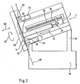
- FIG. 3 is shown in a side view a variant of the invention.
- the cutting blade 4 is formed here as a spiral blade 43.
- W the passive angle of the cutting blade 43 is described, that is, the angle within which no cutting of the food 2 by the cutting edge 42 takes place.
- the passive angle W can be larger or smaller according to the position of the knife 4 relative to the food 2, in particular if, as indicated, a diameter of the food 2 is present, which is slightly smaller than the distance between the initial knife edge 42 and the Surface of the product support 3.
- the chosen configuration of the blade 4 as a spiral blade 43, the blade shaft must not be moved to release the food 2.
- the product support 3 is formed in the illustrated embodiment as a roller belt 34.
- FIGS. 4, 5 the construction of a device 5 and a switching device 54 is shown, which causes the blade 4 and the blade hub 45 between two end positions axially, along the double arrow 55 is adjustable.
- the blade hub 45 is rotatably supported by the bearing 46.
- the hub 45 is driven by the main drive motor (not shown).
- the knife holder 44 is axially displaceable (double arrow 55) mounted in the Mesernabe 45. This can be achieved for example via plain bearing bushes.
- the knife holder 44 is driven by the knife hub 45.
- the operation of the rocker 48 to change the position of the knife via the rod 500 which is arranged at right angles to the spring element 59 of the toggle lever system and extends radially with respect to the blade axis 47.
- the spring element 59 is in this case articulated with the rod 500 connected and extends on both sides of the spring element 59.
- the rod 500 carries at its respective ends depending on a switching cam 56 which cooperates with switching elements 6.
- the longitudinal mobility of the rod 500 is indicated by the arrow 501.
- FIG. 4 are the two switching cam 56, 56 'in cooperation with the switching elements 6, 6' shown.
- the switching cam 56 is actuated by the switching element 6 such that the rod 500 is moved upward and causes a displacement of the blade 4 via the coupling rod 57 via the toggle lever system 58, 59.
- the structure of the Heidelbergelemtes 6 consists of a rotatably mounted roller 60 on a guideway 63 longitudinally displaceable (double arrow 61) angeordent.
- the drive 62 which is designed for example as an electromagnet 62.
- FIG. 4 It is shown how the lower switching element 6 'affects the pivot 502 movably mounted switching cam 56'. In the opposite position it is shown that the switching cam 56 is mounted under the roller 60. If then, if necessary, the position to be changed again, first the roller 60 'by the drive 62' back from the effective range of the switching cam 56 'retract to then control the other switching element 6, the roller 60 on the guide track 63 in the effective range of Shift cam 56 moves.
- the passive time W is indicated as an angular segment of approximately 60 °. Good can be seen that in this Winkelsegement the switching element 6 'switches the cam 56 and so moves the knife.
- the switching element 6 switches the cam 56 and so moves the knife.
- wedge principles or screw movements can be used to realize an offset of the blade 44.
- the proposed positive guidance of the knife ensures that the knife is arranged in any case when re-cutting the next disc or when blank in the defined position. In this case, additional system elements that require a complex control by the machine control, not necessary. It is also ensured by the mechanical forced operation that the movement of the knife with respect to its axial position is independent of the speed or other parameters.
Abstract
Description
Die Erfindung betrifft eine Aufschneidemaschine zum Aufschneiden von Lebensmittel, insbesondere von Wurst-, Fleisch- oder Käseriegeln, wobei das Lebensmittel auf einer Produktauflage aufliegt und ein Schneidmesser am vorderen Ende des Lebensmittels Lebensmittelscheiben abtrennt, wobei sich das Schneidmesser während des Abtrennens der Lebensmittelscheibe in einer Schneidebene befindet und eine Vorrichtung vorgesehen ist, die bewirkt, daß der Abstand zwischen Schneidmesser und vorderem Ende des Lebensmittels veränderbar ist.The invention relates to a slicing machine for slicing food, in particular sausage, meat or cheese bars, wherein the food rests on a product support and a cutting knife at the front end of the food product slices separated, wherein the cutting blade during the separation of the food slice in a cutting plane and a device is provided which causes the distance between the cutting blade and the front end of the food is variable.
Eine vorgenannte Aufschneidemaschine ist zum Beispiel in der
Um den Leerschnitt zu erzeugen, schlägt die vorgenannte europäische Patentanmeldung vor, daß die Produktauflage mit dem Lebensmittel durch einen von der Schneidebene weggerichteten Rückzugshub außerhalb des Wirkbereiches des Messers gebracht wird. Als Schneidebene wird hierbei die Ebene angesehen in der sich die Messerschneide während des Abtrennes der Lebensmittelscheibe befindet.To produce the blank cut, the aforementioned European patent application proposes that the product support with the food be brought out of the effective range of the knife by a retraction stroke directed away from the cutting plane. As a cutting plane in this case the plane is considered in which the knife edge is located during the separation of the food disc.
Nun ist zu beachten, daß die aufzuschneidenden Lebensmittelriegel beachtliche Dimensionen erreichen. Die Riegel können eine Länge von bis zu 160 cm und ein Gewicht von 50 Kilo und mehr aufweisen. Die Konsistenz des aufzuschneidenen Produktes, reicht entsprechend der verarbeitungstemperatur von verhältnismäßig fest bis elastisch deformierbar. Auf Grund der hohen Taktfrequenzen, besteht nur eine verhältnismäßig kurze Zeit, innerhalb der das Produkt aus dem Wirkbereich des Schneidmessers zurückzuziehen ist. Hieraus resultieren verhältnismäßig große Beschleunigungen, damit verbunden auch hohe Kräfte, die auf die Produktauflage bzw. dem darauf aufliegendem Lebensmittelriegel eingeprägt werden müssen, um diesen zurückzuziehen. Gelingt es nicht den Lebensmittelriegel innerhalb des vorgesehen Zeitsegmentes ausreichend zurückzuziehen, so ist es unvermeidlich, daß das Schneidmesser eine unvollständige Scheibe abtrennt, Scheibenschnitzel erzeugt, oder sonst ungewollte Schneidbewegungen durchführt. Dies führt regelmäßig zu einer Ausschußportion und zusätzlichen Verschmutzungen des Schneidmessers, da die halbabgetrennten Scheiben unter Umständen nicht wie vorgesehen vom Schneidmesser auf die Produktauflage abfallen.Now it should be noted that the sliced food bars reach considerable dimensions. The bars can have a length of up to 160 cm and a weight of 50 kilos and more. The consistency of the sliced product ranges from relatively firm to elastically deformable according to the processing temperature. Due to the high clock frequencies, there is only a relatively short time within which the product is to be withdrawn from the effective range of the cutting blade. This results in relatively large accelerations, associated with high forces that must be stamped on the product support or the food bar resting thereon in order to withdraw this. If it is not possible to sufficiently retract the food bar within the time frame provided, it is unavoidable that the cutting knife cuts off an incomplete slice, generates slice chips, or otherwise performs unwanted cutting movements. This regularly leads to a debris portion and additional contamination of the cutting blade, since the semi-separated discs may not drop as intended by the cutting blade on the product support.
Das auf der Produktauflage aufliegende Lebensmittel stellt im Prinzip ein schwingendes System dar. Die Neigungen zur Aufnahme von Schwingungen wird noch durch die variabilität der Konsistenz des Lebensmittels erhöht. Auf dieses Schwingungssystem sind kurzzeitig verhältnismäßig hohe Kräfte einzuprägen, um diese aus dem Wirkbereich des Messers zu bringen, um das Durchführen der Leerschnitte zu ermöglichen. Diese eingeprägten Schwingungen erzeugen unter Umständen eine ungewünschte Längendeformation des Lebensmittelriegels, die dazu führen kann, daß die Rückzugsbewegung nicht ausreicht um die ungewünschte Schnitzelbildung zu vermeiden.The food resting on the product support is in principle a vibrating system. The inclination to absorb vibrations is further increased by the variability of the consistency of the food. For a short time relatively high forces are to be impressed on this vibration system in order to bring it out of the effective range of the blade, in order to allow the passage of the idle cuts. These impressed vibrations may produce an undesirable length deformation of the food bar, which can cause the return movement is not sufficient to avoid the unwanted chips formation.
Die Erfindung hat sich zur Aufgabe gemacht, die vorgenannte Aufschneidemaschine dahingehend zu verbessern, daß auch bei hohen Schneidleistungen der Aufschneidemaschine die Gefahr einer Schnitzelbildung zuverlässig vermieden wird.The invention has set itself the task of improving the aforementioned slicing machine to the effect that even with high cutting performance of the slicing machine, the risk of chips formation is reliably avoided.
Zur Lösung dieser Aufgabe geht die Erfindung aus, von einer Aufschneidemaschine, wie eingangs beschrieben, und schlägt vor, daß das Schneidmesser gegenüber der Produktauflage bzw. der Schneidebene beweglich ist und die Vorrichtung eine Bewegung des Schneidmessers aus der Schneidebene, vom Lebensmittel weg, bewirkt.To achieve this object, the invention is based on a slicing machine, as described above, and suggests that the cutting blade relative to the product support or the cutting plane is movable and the device causes a movement of the cutting blade from the cutting plane, away from the food.
Durch den erfindungsgemäßen Vorschlag wird erreicht, daß auf das Lebensmittel keine schnelle Rückzugsbewegung eingeprägt werden muß, die zum einen der normalen Förderbewegung des Lebensmittels entgegengerichtet ist und gleichzeitig zu den unerwünschten Schwingungen im Lebensmittel führen würde. Durch die erfindungsgemäße Ausgestaltung wird auch unabhängig von den sonstigen Betriebsparametern (gekühlte bzw. gefrorene oder weichere, bei Zimmertemperatur verarbeiteten Lebensmittel) gleichbleibend gute Ergebnisse bei dem Aufschneiden der Lebensmittelriegel erhalten.By the proposal according to the invention it is achieved that the food no rapid retraction movement must be impressed, which is contrary to a normal conveying movement of the food and would also lead to the unwanted vibrations in the food. The inventive design is also independent of the other operating parameters (cooled or frozen or softer, processed at room temperature food) consistently good results obtained in the slicing of food bars.
Der erfindungsgemäße Vorschlag sieht vor, daß das Schneidmesser gegenüber der Produktauflage bzw. Schneidebene beweglich ausgebildet ist. Es ist somit vorgesehen, daß nur das Schneidmesser, welches ja für die Abtrennung der Scheiben verantwortlich ist, durch die Vorrichtung bewegt wird.The proposal according to the invention provides that the cutting blade is designed to be movable relative to the product support or cutting plane. It is thus provided that only the cutting blade, which is indeed responsible for the separation of the discs, is moved through the device.
In einer anderen Variante der erfindungsgemäßen Ausgestaltung ist vorgesehen, daß das Schneidmesser gegenüber der Produktauflage längsbeweglich gelagert ist.In another variant of the embodiment according to the invention it is provided that the cutting blade is mounted longitudinally movable relative to the product support.
Erfindungsgemäß wird auch vorgeschlagen, daß die Vorrichtung einen Linearantrieb aufweist. Der Linearantrieb greift hierbei zum Beispiel an den längsbeweglichen gelagerten Schneidmesser an und bewegt diese bei Bedarf.According to the invention, it is also proposed that the device has a linear drive. The linear drive acts, for example, on the longitudinally movable mounted cutting blade and moves it if necessary.
Hierbei ist es von Vorteil, daß die Vorrichtung mit der Maschinensteuerung verbunden ist und die entsprechenden Informationen von der Steuerung erhält. Der Antrieb kann hierbei als hydraulisch oder pneumatisch beaufschlagbar Arbeitszylinder ausgestaltet sein oder aber mit einem entsprechenden elektrischen oder elektromagnetischen Antrieb ausgestaltet sein.It is advantageous that the device is connected to the machine control and receives the corresponding information from the controller. The drive can in this case be configured as a hydraulically or pneumatically actuable working cylinder or be configured with a corresponding electric or electromagnetic drive.
In einer Variante der Erfindung ist vorgesehen, daß die Vorrichtung Mittel aufweist, durch die die Bewegung des Schneidmessers zumindest zeitweise von der Bewegung des Schneidmessers abgeleitet wird. Es ist zum Beispiel vorgesehen, in dem Planetengetriebe oder dem Antrieb des Schneidmessers bei Bedarf ein Distanzstück zuzuschalten, das bewirkt, daß das Schneidmesser einen gewissen Abstand von dem aufzuschneidenden Lebensmittel einnimmt.In a variant of the invention it is provided that the device comprises means by which the movement of the cutting blade is at least temporarily derived from the movement of the cutting blade. It is envisaged, for example, to switch on a spacer in the planetary gear or the drive of the cutting blade if necessary, which causes the cutting blade to occupy a certain distance from the food to be sliced.
Die Erfindung sieht auch vor, daß es günstig ist, wenn die Vorrichtung die Messerwelle bewegt. Die Messerwelle ist zum Beispiel im gewissen Bereich teleskopierbar ausgebildet und die Teleskopierbarkeit kann für einen Versatz des Messers ausgenützt werden. Ebenso kann die Vorrichtung an der Messerwelle angreifen und einen Versatz der gesamten Messerwelle zum Beispiel gegen eine rücktreibende Federkraft bewirken.The invention also provides that it is beneficial if the device moves the knife shaft. For example, the blade shaft can be telescoped in a certain range and the telescoping capability can be exploited for an offset of the blade. Likewise, the device on the blade shaft attack and cause an offset of the entire blade shaft, for example, against a restoring spring force.
Es ist vorgesehen, daß das Schneidmesser als rotationssymmetrische Messerscheibe ausgebildet ist. Für das Freigeben des Lebensmittels ist es hierbei günstig, wenn das Schneidmesser zum Beispiel planetenartig umläuft. Alternativ hierzu kann aber auch vorgesehen werden, das Schneidmesser als Spiralmesser auszubilden. Das Spiralmesser besitzt eine auf seinen Außenflächen liegende Schneide und ergibt den Vorteil, daß das aufzuschneidende Lebensmittel ohne Bewegung des Schneidmessers periodisch freigegeben wird. Das Freigeben ist notwendig um das aufzuschneidende Lebensmittel in den Wirkbereich des Messers zu bringen. Durch die Ausgestaltung der Messerschneide mit einer Spiral- bzw. Schraubenkurve kann dabei der Wirkbereich bzw. Einwirkbereich (Aktivzeit) des Messers in das Lebensmittel definiert werden.It is envisaged that the cutting blade is formed as a rotationally symmetrical cutter disc. For the release of the food, it is advantageous if the cutting blade, for example, rotates like a planet. Alternatively, however, can also be provided to form the cutting blade as a spiral knife. The spiral knife has a blade located on its outer surfaces and provides the advantage that the food to be cut is released periodically without movement of the cutting blade. The release is necessary to bring the food to be sliced into the effective range of the knife. Due to the configuration of the knife edge with a spiral or screw curve, the effective range or area of action (active time) of the knife in the food can be defined.
Neben der Ausgestaltung des Schneidmessers als Spiralmesser ist es aber auch möglich ein Sichelmesser, also ein Messer mit "innenliegender Schneide" vorzusehen, die ebenfalls bei stillstehender Rotationsachse des Messers, das Schneidgut periodisch freigibt. Gerade die Ausgestaltung des Schneidmessers als Spiralmesser oder als Sichelmesser hat den Vorteil, daß ohne die Rotationsachse des Messers zu bewegen, das Lebensmittel periodisch freigegeben wird. Dadurch kann das verhältnismäßig aufwendige Planetengetriebe eingespart werden.In addition to the design of the cutting blade as a spiral knife, but it is also possible to provide a sickle blade, so a knife with "internal cutting", which also releases the cutting material periodically with stationary rotation axis of the knife. Especially the configuration of the cutting blade as a spiral knife or as a sickle knife has the advantage that without moving the axis of rotation of the knife, the food is released periodically. As a result, the relatively complex planetary gear can be saved.
Es ist günstig, daß die Vorrichtung als Umschaltvorrichtung ausgebildet ist, die einen axialen Versatz des Messers zwischen zwei kraftbeaufschlagten Endstellungen bewirkt. Eine Kraftbeaufschlagung der Endstellungen ist günstig, daß genaue definierte Endlagen bestehen und keine unkontrollierte axiale Bewegung des Messers auftreten, die gegebenenfalls zu den unerwünschten Schnitzelbildungen führen würden.It is favorable that the device is designed as a switching device, which causes an axial displacement of the blade between two force-loaded end positions. A force applied to the end positions is favorable that exact defined end positions exist and no uncontrolled axial movement of the knife occur, which would possibly lead to the unwanted Schnitzelbildungen.
In einer Weiterentwicklung der Erfindung ist vorgesehen, die Umschaltvorrichtung im wesentlichen auf der Messerwelle bzw. der Messernabe mitlaufend auszubilden und mindestens einen Schaltnocken vorzusehen, der von mindestens einem ansteuerbaren Schaltelement zwischen den Endstellungen schaltbar ist. Durch diesen erfindungsgemäßen Vorschlag wird erreicht, daß mit verhältnismäßig wenig Kraft des zu steuerndem Schaltelement die Umschaltvorrichtung an dem schnell rotierenden Messer geschaltet wird. Dabei wird die Rotationsenergie des Messers gezielt eingesetzt, um das Messer axial zu versetzen. Hierbei ist zu beachten, daß das Schaltelement ohne Last oder Beaufschlagung schaltbar ist und somit geringe Schaltkräft wie sie zum Beispiel von einem Elektromagneten abgeleitet werden können, einsetzbar sind.In a further development of the invention, it is provided that the switching device essentially follow the blade shaft or the knife hub and provide at least one switching cam which can be switched by at least one controllable switching element between the end positions. By this proposal according to the invention it is achieved that with relatively little force of the switching element to be controlled, the switching device is switched to the fast rotating knife. The rotational energy of the knife is used selectively to move the knife axially. It should be noted that the switching element is switchable without load or loading and thus low switching forces as they can be derived, for example, by an electromagnet used.
Des weiteren ist es von Vorteil, wenn die Umschaltvorrichtung bzw. Vorrichtung in der Aktivzeit des Schneidmessers durch ein Schaltelement vorschaltbar ist und während der Passivzeit des Schneidmessers zwischen den Endstellungen umschaltet. Dies ist gerade zum Beispiel bei der Ausgestaltung der Erfindung mit dem Schaltnocken von Vorteil, da die Schaltnocke periodisch mit dem Messer umläuft und nur das Schaltelement geschaltet werden muß, um rechtzeitig den Schaltnocken zu betätigen. Als Aktivzeit des Messers wird hierbei der Zeitanteil der periodischen Schneidbewegung angesehen, innerhalb der das Schneidmesser entweder in das Lebensmittel eindringt, oder aber, wie bei dem Leerschnitt, in das Lebensmittel nicht eintritt aber sich in gleichen Winkelsegment befindet. Als Passivzeit wird hierbei die restliche Zeit angesehen, innerhalb der das Schneidmesser das Lebensmittel zum Vorfördern des Lebensmittels vollständig freigibt.Furthermore, it is advantageous if the switching device or device in the active time of the cutting blade is vorschaltbar by a switching element and switches during the passive time of the cutting blade between the end positions. This is just for example in the embodiment of the invention with the switching cam advantageous because the switching cam periodically rotates with the knife and only the switching element must be switched to operate the switching cam in a timely manner. As the active time of the knife here the time proportion of the periodic cutting movement is considered, within which the cutting blade either penetrates into the food, or, as in the blank cut, does not enter the food but is in the same angular segment. The passive time is considered to be the remaining time within which the cutting knife completely releases the food for advancing the food.
Durch die erfindungsgemäße Weiterentwicklung ist es dabei möglich, den Vorschaltvorgang, also das Positionieren des Schaltelementes für das Zusammenwirken mit dem Schaltnocken in der verhältnismäßig langen Aktivzeit vorzunehmen, weswegen hier verhältnismäßig kleinere Beschleunigungen ausreichen und die notwendigen Kräfte und die daraus resultierenden Schwingungen geringer sind. In der Passivzeit des Schneidmessers wird dann der eigentliche Umschaltvorgang durchgeführt, nämlich ein axialer Versatz des Messers bewirkt. Dabei ist es möglich durch die Wahl der Ausgestaltung des Messers, insbesondere des Spiral- oder Sichelmessers, den Anteil an Aktiv- und Passivzeit entsprechend zu steuern. Auch kann auf Grund der Messerstellung auf der Nabe im Verhältnis zu den Schaltnocken eine feste mechanische zwangsführung realisiert werden und so die gesamte Aufschneidemaschine von aufwendigen Steuerungsproblemen entlastet werden. Dabei ist das System auch unabhängig von der gewählten Rotationsgeschwindigkeit.The inventive development, it is possible to make the Vorschaltvorgang, ie the positioning of the switching element for the interaction with the switching cam in the relatively long active time, which is why relatively smaller accelerations sufficient and the necessary forces and the resulting vibrations are lower. In the passive time of the cutting blade, the actual switching operation is then carried out, namely causes an axial offset of the blade. It is possible by the choice of the configuration of the knife, in particular the spiral or sickle blade to control the proportion of active and passive time accordingly. Also, due to the knife position on the hub in relation to the switching cams a fixed mechanical positive guidance can be realized and so the entire slicing machine are relieved of complex control problems. The system is also independent of the selected rotation speed.
In der Zeichnung ist die Erfindung schematisch dargestellt. Es zeigen:
- Fig. 1
- in einer Seitenansicht eine erste Ausgestaltung der Aufschneidemaschine;
- Fig. 2
- ebenfalls in einer Seitenansicht eine weitere Ausgestaltung der Aufschneidemaschine;
- Fig. 3
- in einer Frontansicht einen Ausschnitt der erfindungsgemäßen Aufschneidemaschine, insbesondere das Schneidmesser im Zusammenwirken mit dem Lebensmittel;
- Fig. 4
- in einem Detail die Umschaltvorrichtung bzw. die Vorrichtung der erfindungsgemäßen Aufschneidemaschine, in einer Ansicht;
- Fig. 5
- eine geschnitte Seitenansicht gemäß
Figur 4 , der erfindungsgemäßen Aufschneidemaschine.
- Fig. 1
- in a side view, a first embodiment of the slicing machine;
- Fig. 2
- likewise in a side view a further embodiment of the slicing machine;
- Fig. 3
- in a front view of a section of the slicing machine according to the invention, in particular the cutting blade in cooperation with the food;
- Fig. 4
- in a detail, the switching device or the device of the slicing machine according to the invention, in a view;
- Fig. 5
- a cut side view according to
FIG. 4 , the slicing machine according to the invention.
Die Aufscheidemaschine 1 besteht aus einem Produktzuführ- und Aufschneidelement 12, welches von dem Gestell 11 getragen auf einem Unterbau 10 ruht. Das Element 12 ist hierbei geneigt angeordnet, um die Hangabtriebskraft bei der Förderung des Lebensmittels 2 durch die Fördervorrichtung 30 unterstützend auszunützen. Die Winkeleinstellung des Elementes 12 ist bei Varianten der Aufschneidemaschine veränderlich ausgebildet.The
Das Lebensmittel 2, welches zum Beispiel ein Wurst-, Fleisch- oder Käseriegel ist, liegt auf der Produktauflage 3 auf. Die Produktauflage 3 ist hierbei zum Beispiel eine Rollenbahn oder ein Förderband und gestattet ein möglichst leichtgängiges Transportieren des Lebensmittels 2.The
Das Lebensmittel 2 wird hierbei von einer Fördervorrichtung 30 gegen das Schneidmesser 4 gefördert. Die Fördervorrichtung 30 ist zum Beispiel durch einen Spindelantrieb 32 gebildet, auf welchem ein Kopplungselement 31 schlittenartig geführt ist. Durch die Rotation der Spindel 32 bewegt sich das schlittenartige Kopplungselement 31. Das Kopplungselement 31 ist zum Beispiel klammerartig ausgestaltet und ergreift das rückseitige Ende des Lebensmittels 2. Durch das Kopplungselement 31 wird die Förderbewegung, die durch den Spindelantrieb 32 auf das Kopplungselement 31 eingeprägt wird, auf das Lebensmittel 2 übertragen. Für die Ausgestaltung der Fördervorrichtung 3 sind aber auch viele andere Ausgestaltungen bekannt und einsetzbar.The
Das Schneidmesser 4 befindet sich in einem Schneidmessergehäuse 40. Das Schneidmesser 4 besitzt einen nicht weiter dargestellten Schneidmesserantrieb, der das Schneidmesser 4 in Rotation 41 versetzt. Das Schneidmesser 4 ist zum Beispiel auf einen Planetengetriebe angeordnet und führt so neben der Rotation um seine Drehachse auch eine Rotation der Drehachse um die Achse des Planetengetriebes aus. Hieraus resultiert, daß das Schneidmesser 4 periodisch umläuft und zum Beispiel von oben an das Lebensmittel 2 heranfahrend in dieses eindringt und eine Lebensmittelscheibe (nicht dargestellt) abtrennt, die dann nach unten auf ein ebenfalls nicht dargestelltes Förderband fallen läßt. Durch die planetenartige Umlaufbewegung des Schneidmessers 4 wird das vordere Ende 20 des Lebensmittels 2 regelmäßig wieder freigegeben und die Fördervorrichtung 30 fördert in diesem Zeitsegment das Lebensmittel 2 gerade um die Scheibendicke nach vorne. Das Freigeben des vorderen Endes 20 des Lebensmittels 2 kann aber auch auf andere Weise erreicht werden. Zum Beispiel kann vorgesehen werden, daß Schneidmesser 4 auf einer Schienenführung anzuordnen die so eingestellt ist, daß in gleicher Weise das Lebensmittel 2 erreicht und freigegeben wird. Diese Schienenführung kann zum Beispiel nach oben oder zur Seite angeordent sein.The cutting blade 4 is located in a
Erfindungsgemäß wird vorgeschlagen, daß eine Vorrichtung 5 angeordnet ist, die bewirkt, daß der Abstand zwischen dem Schneidmesser 4 und dem vorderen Ende 20 des Lebensmittels 2 veränderbar ist. Hierbei wird das Schneidmesser 4 bzw. das Schneidmessergehäuse 40 gegenüber der Produktauflage 3 bzw. der Schneidebene 49 oder dem Gestell 11 vom Lebensmittel 2 wegbewegt. Die eigentliche Schneidebene 49 verändert sich durch diese Ausgestaltung nicht. Die Schneidebene 49 ist definiert durch die Bewegung der Schneide 42 während des Abtrennens einer Lebensmittelscheibe, bzw. durch das Zusammenwirken der Schneide 42 des Schneidmessers 4 und der Schneidkante 33. Die Schneidkante 33 befindet sich am, dem Schneidmesser 4 zugewandten Ende der Produktauflage und bildet ein Widerlager zu der durch die Schneide 42 in das Lebensmittel 2 eingeprägten Schneidkraft. Die Schneidkante 33 befindet sich hierbei geometrisch nicht exakt auf der Schneideben 49, dies würde zu einer Kollision der Schneide 42 auf der Schneidkante 33 führen, sondern ist an der Schneidebene 49 derart angeordnet, daß das Schneidmesser 4 knapp daneben vorbeizulaufen vermag. Es ist wichtig, daß die Schneidkante 33 verhältnismäßig exakt mit dem Schneidmesser 4 zusammmenwirkt und so die Messerschneidebene definiert, da ein Auseinanderklaffen dieser beiden Elemente unweigerlich zu unerwünschten Schneidergebnissen führt. Ein Versatz von wenigen Millimetern kann bereits zu unerwünschten Ergebnissen, zum Beispiel einem "Zerhacken" des Aufschnittes führen.According to the invention it is proposed that a
Auf Grund der hohen Produktionsleistung, die mit der erfindungsgemäßen Aufschneidemaschinen erreicht werden, ist es günstig, daß die Aufschneidemaschine 1 bei Anforderung ein oder mehrere Leerschnitte durchführt, um die unerwünschte Schnitzelbildung zu vermeiden.Due to the high production capacity achieved with the slicing machines according to the invention, it is favorable that the slicing
In einer Variante der Erfindung ist aber auch vorgesehen, daß dieser Linearantrieb nur auf die Messerwelle wirkt und ein Versatz des Schneidmessers 4, bei feststehenden Antrieb und bei feststehenden Schneidmessergehäuse 40 bewirkt. Es ist klar, daß sich bei dieser Bewegung das Messer 4 aus der zuvor definierten Schneidebene 49 nach vorne, in Förderrichtung 21 des Lebensmittels 2, vom Lebensmittel 2 weg, bewegt.In a variant of the invention but also provided that this linear drive only on the blade shaft acts and causes a displacement of the cutting blade 4, with fixed drive and fixed
In
In
Um das Schneidmesser 4, 43 leicht von der Messeraufnahme 44 abbauen zu können, sind eine Mehrzahl von Schraubverbindungen vorgesehen. Die Produktauflage 3 ist in dem dargestellten Ausführungsbeispiel als Rollenband 34 ausgebildet.To be able to easily remove the
In den
Über die Koppelstange 57 wird die Messeraufnahme 44 axial in die jeweilige Position gebracht. Diese Koppelstange 57 ist mit einem Hebelsystem verbunden. Das Hebelsystem wird gebildet von der Schwinge 58 und dem Federelement 59. Das Zusammenwirken dieser Elemente 58, 59 bewirkt, das die Koppelstange 57 in der jeweiligen Endlage kraftbeaufschlagt verharrt und so die beiden Endstellungen der Messeraufnahme 44 bzw. des Schneidmessers 4 definiert.About the
Das Betätigen der Schwinge 48 zum Wechseln der Stellung des Messers erfolgt über die Stange 500, die zu dem Federelement 59 des Kniehebelsystemes im wesentlichen rechtwinklig angeordnet ist und sich radial bezüglich der Messerachse 47 erstreckt. Das Federelement 59 ist hierbei mit der Stange 500 gelenkig verbunden und erstreckt sich beidseitg des Federelementes 59. Die Stange 500 trägt an seinen jeweiligen Enden je einen Schaltnocken 56 der mit Schaltelementen 6 zusammenwirkt. Die Längsbeweglichkeit der Stange 500 ist mit dem Pfeil 501 angedeutet.The operation of the rocker 48 to change the position of the knife via the
In
Für ein Vor- und Zurückbewegen der Messeraufnahme 44 zwischen den beiden Endstellungen ist vorgesehen, daß ein Schaltelement 6 links und ein Schaltelement 6' rechts von der Stange 500 angeordent sind.For a forward and backward movement of the
Der Aufbau des Schaltelemtes 6 besteht aus einer drehbar gelagerten Rolle 60 die auf einer Führungsbahn 63 längs verschiebbar (Doppelpfeil 61) angeordent sind. Für die Längsbeweglichkeit dient der Antrieb 62, der zum Beispiel als Elektromagnet 62 ausgebildet ist.The structure of the
In
In
Claims (7)
- Slicing machine for slicing food, in particular sausage, meat or cheese bars, the food resting on a product rest, and a rotationally driven cutting blade at the front end of the food cutting off food slices, the cutting blade being located in a cutting plane during the cutting-off of the food slice, and a device being provided which enables the distance between the cutting blade and the front end of the food to be varied, and the cutting blade (4) and the device (5, 54) each having a separate drive, characterized in that the cutting blade (4) is movably mounted relative to the product rest (3) and parallel to the rotation axis of the cutting blade, the device (5, 54) for carrying out one or more idle cuts producing a movement of the cutting blade from the cutting plane, away from the food, and the device having a driven blade hub (45) and the cutting blade (4) being arranged on a blade receptacle (44) which is mounted in the blade hub in an axially displaceable manner.
- Slicing machine according to Claim 1, characterized in that the cutting blade (4) is designed to orbit in a planetary manner.
- Slicing machine according to either of the preceding claims, characterized in that the cutting blade (4) is designed as a rotationally symmetrical cutter disc.
- Slicing machine according to one or more of the preceding claims, characterized in that the cutting blade (4) is designed as a spiral blade (43) or crescent blade.
- Slicing machine according to one or more of the preceding claims, characterized in that the device (5) is activated in the time segment in which the blade (4) does not engage in the food (2).
- Slicing machine according to one of the preceding claims, characterized in that the device has a linear drive.
- Slicing machine according to one of the preceding claims, characterized in that the drive is a working cylinder which can be acted upon hydraulically or pneumatically or an electric or electromagnetic drive.
Applications Claiming Priority (3)
| Application Number | Priority Date | Filing Date | Title |
|---|---|---|---|
| DE19917536 | 1999-04-19 | ||
| DE19917536A DE19917536A1 (en) | 1999-04-19 | 1999-04-19 | Slicer for cutting food bars |
| EP00107763A EP1046476B8 (en) | 1999-04-19 | 2000-04-11 | Slicing machine for slicing food loaves |
Related Parent Applications (2)
| Application Number | Title | Priority Date | Filing Date |
|---|---|---|---|
| EP00107763.5 Division | 2000-04-11 | ||
| EP00107763A Division EP1046476B8 (en) | 1999-04-19 | 2000-04-11 | Slicing machine for slicing food loaves |
Publications (2)
| Publication Number | Publication Date |
|---|---|
| EP1552912A1 EP1552912A1 (en) | 2005-07-13 |
| EP1552912B1 true EP1552912B1 (en) | 2012-02-29 |
Family
ID=7905015
Family Applications (2)
| Application Number | Title | Priority Date | Filing Date |
|---|---|---|---|
| EP05007281A Expired - Lifetime EP1552912B1 (en) | 1999-04-19 | 2000-04-11 | Slicing machine for slicing food loaves |
| EP00107763A Expired - Lifetime EP1046476B8 (en) | 1999-04-19 | 2000-04-11 | Slicing machine for slicing food loaves |
Family Applications After (1)
| Application Number | Title | Priority Date | Filing Date |
|---|---|---|---|
| EP00107763A Expired - Lifetime EP1046476B8 (en) | 1999-04-19 | 2000-04-11 | Slicing machine for slicing food loaves |
Country Status (5)
| Country | Link |
|---|---|
| EP (2) | EP1552912B1 (en) |
| AT (2) | ATE293521T1 (en) |
| DE (3) | DE19917536A1 (en) |
| DK (1) | DK1046476T3 (en) |
| ES (1) | ES2239955T3 (en) |
Cited By (1)
| Publication number | Priority date | Publication date | Assignee | Title |
|---|---|---|---|---|
| US8549966B2 (en) | 2007-10-22 | 2013-10-08 | Formax, Inc. | Output conveyor for a food article slicing machine |
Families Citing this family (27)
| Publication number | Priority date | Publication date | Assignee | Title |
|---|---|---|---|---|
| DE10052756A1 (en) * | 2000-03-31 | 2001-10-11 | Gebr Graef Gmbh & Co Kg | Slicing machine, especially for cheese, allows both round and wedge shaped blocks to be cut into slices |
| DE10147348A1 (en) * | 2001-09-26 | 2003-04-17 | Weber Maschb Gmbh & Co Kg | Device for slicing food products |
| DE10148595A1 (en) * | 2001-10-02 | 2003-04-10 | Weber Maschb Gmbh & Co Kg | Delicatessen slicing machine for e.g. ham, cheese, sausage has blade that rests on carriage which is adjustable in vertical and horizontal planes |
| DE10359149A1 (en) * | 2003-12-16 | 2005-07-21 | Cfs Kempten Gmbh | Food slicing assembly for e.g. cheese or sausage has blade that moves between slices under control of regulated drive system |
| DE10333662A1 (en) * | 2003-07-23 | 2005-02-10 | Cfs Gmbh Kempten | Cutting head of an eccentric cutting machine |
| DE10333661A1 (en) * | 2003-07-23 | 2005-02-10 | Cfs Kempten Gmbh | Food slicing assembly for e.g. cheese or sausage has blade that moves between slices under control of regulated drive system |
| WO2005009696A1 (en) * | 2003-07-23 | 2005-02-03 | Cfs Kempten Gmbh | Axially-displaceable cutter and cutting gap adjustment |
| DE102008019776A1 (en) | 2008-04-18 | 2009-10-22 | CFS Bühl GmbH | Method, device and knife for slicing food |
| DE102009038875A1 (en) | 2009-08-26 | 2011-03-03 | Weber Maschinenbau Gmbh Breidenbach | drive motor |
| DE102009048056A1 (en) * | 2009-10-02 | 2011-04-07 | CFS Bühl GmbH | Cutterhead with integrated drives |
| ES2556634T3 (en) * | 2009-12-02 | 2016-01-19 | Weber Maschinenbau Gmbh Breidenbach | Device for cutting food products |
| DE102009056670A1 (en) | 2009-12-02 | 2011-06-09 | Weber Maschinenbau Gmbh Breidenbach | Apparatus i.e. slicer, for slicing e.g. food product, has cutting blade that is pivotable, where cutting blade remains aligned parallel to cutting plane or departs from parallel alignment |
| DE102010008047A1 (en) | 2010-02-16 | 2011-08-18 | Weber Maschinenbau GmbH Breidenbach, 35236 | Apparatus i.e. slicer, for slicing e.g. food product, has cutting blade that is pivotable, where cutting blade remains aligned parallel to cutting plane or departs from parallel alignment |
| DE102010011172A1 (en) | 2010-03-12 | 2011-09-15 | Weber Maschinenbau Gmbh Breidenbach | Device for cutting open of food products, particularly high speed slicer, comprises product supply unit, which is formed to supply product to be cut along feed direction to cutting plane, in which cutting knife is moved |
| DE102009059856A1 (en) | 2009-12-21 | 2011-06-22 | Weber Maschinenbau GmbH Breidenbach, 35236 | Device for cutting open of food products, particularly high speed slicer, comprises product supply unit, which is formed to supply product to be cut along feed direction to cutting plane, in which cutting knife is moved |
| EP2357064B1 (en) | 2009-12-21 | 2015-09-23 | Weber Maschinenbau GmbH Breidenbach | Device for cutting a food product |
| DE102010013892A1 (en) | 2010-04-07 | 2011-10-13 | Weber Maschinenbau Gmbh Breidenbach | Device for slicing food products |
| DE102010013891A1 (en) | 2010-04-07 | 2011-10-13 | Weber Maschinenbau Gmbh Breidenbach | Device for slicing food products |
| DE102010013893A1 (en) | 2010-04-07 | 2011-10-13 | Weber Maschinenbau Gmbh Breidenbach | Device for slicing food products |
| DE102010019744B4 (en) * | 2010-05-07 | 2020-11-26 | Weber Maschinenbau Gmbh Breidenbach | Device for slicing food products |
| EP2807004B2 (en) | 2012-01-26 | 2022-09-21 | GEA Food Solutions Germany GmbH | Slicing in the package |
| DE102013206255A1 (en) | 2012-04-16 | 2013-10-17 | GEA CFS Bühl GmbH | Blank cutting rotor for use in slicing apparatus for cutting e.g. cheese, has inner sleeve shaft rotatably supported within housing, linear drive engaging end of linkage and axially moving linkage, and bearing supported at housing |
| DE102012207303A1 (en) | 2012-05-02 | 2013-11-07 | Weber Maschinenbau Gmbh Breidenbach | Apparatus for slicing e.g. meat, has axial drive to move rotor along axial direction, to perform blank cuts so as to form cutting gap, and rotary drive whose portion is implemented along axial direction through axial drive |
| DE102012207304A1 (en) | 2012-05-02 | 2013-11-21 | Weber Maschinenbau Gmbh Breidenbach | Driving apparatus for cutting knife of high performance slicer, for cutting e.g. food product, has carrier whose pure rotational motion or rotational motion with additional axial movement is produced parallel to rotational axis |
| DE102012219594A1 (en) * | 2012-10-25 | 2014-04-30 | Textor Maschinenbau GmbH | Method and device for slicing food products |
| CN108501091B (en) * | 2018-02-10 | 2020-05-22 | 金华市坤麦科技有限公司 | Sausage pattern cutting device with high safety performance |
| WO2020172051A1 (en) * | 2019-02-22 | 2020-08-27 | Provisur Technologies, Inc. | Pivoting blade assembly for high-speed food slicing machine |
Family Cites Families (10)
| Publication number | Priority date | Publication date | Assignee | Title |
|---|---|---|---|---|
| DE154952C (en) * | ||||
| US4523501A (en) * | 1983-09-19 | 1985-06-18 | Oscar Mayer Foods Corporation | Slicer feed mechanism |
| DE3617336A1 (en) | 1986-05-23 | 1987-11-26 | Guenther Weber | METHOD AND DEVICE FOR FORMING WEIGHT-CONSTANT PORTIONS OR STACKS OF SLICED FOOD PRODUCTS |
| DE3714810A1 (en) * | 1987-05-04 | 1988-11-17 | Guenther Weber | CIRCULAR CUTTER |
| DE4214264C2 (en) * | 1992-05-01 | 1994-06-01 | Natec Reich Summer Gmbh Co Kg | CUTTING DEVICE FOR SLICING FOOD PRODUCTS, ESPECIALLY SAUSAGE, HAM, BACON, MEAT, CHEESE AND THE LIKE |
| DE4402923A1 (en) | 1994-02-01 | 1995-08-03 | Dixie Union Verpackungen Gmbh | Device for inserting pieces of paper into cold cuts |
| DE4406868A1 (en) | 1994-03-02 | 1995-09-07 | Biforce Anstalt | Method and device for forming stacks from individual slices of a food product |
| DE19518595C2 (en) * | 1995-05-20 | 1999-02-25 | Schindler & Wagner Kg | Cutting machine |
| DE19739788A1 (en) | 1997-09-10 | 1999-03-11 | Alpma Alpenland Masch | Cutter knife for food slicer |
| NL1009772C1 (en) * | 1998-07-30 | 2000-02-01 | Foodcorner International B V | Method and device for slicing foodstuffs. |
-
1999
- 1999-04-19 DE DE19917536A patent/DE19917536A1/en not_active Withdrawn
-
2000
- 2000-04-11 DE DE20024024U patent/DE20024024U1/en not_active Expired - Lifetime
- 2000-04-11 EP EP05007281A patent/EP1552912B1/en not_active Expired - Lifetime
- 2000-04-11 DK DK00107763T patent/DK1046476T3/en active
- 2000-04-11 ES ES00107763T patent/ES2239955T3/en not_active Expired - Lifetime
- 2000-04-11 DE DE50010076T patent/DE50010076D1/en not_active Expired - Lifetime
- 2000-04-11 AT AT00107763T patent/ATE293521T1/en not_active IP Right Cessation
- 2000-04-11 AT AT05007281T patent/ATE547217T1/en active
- 2000-04-11 EP EP00107763A patent/EP1046476B8/en not_active Expired - Lifetime
Cited By (3)
| Publication number | Priority date | Publication date | Assignee | Title |
|---|---|---|---|---|
| US8549966B2 (en) | 2007-10-22 | 2013-10-08 | Formax, Inc. | Output conveyor for a food article slicing machine |
| US8850938B2 (en) | 2007-10-22 | 2014-10-07 | Formax, Inc. | Maintenance and safety system for a food article slicing machine |
| US8978529B2 (en) | 2007-10-22 | 2015-03-17 | Formax, Inc. | Food article feed apparatus for a food article slicing machine |
Also Published As
| Publication number | Publication date |
|---|---|
| EP1552912A1 (en) | 2005-07-13 |
| DE19917536A1 (en) | 2000-10-26 |
| DE20024024U1 (en) | 2010-05-12 |
| ES2239955T3 (en) | 2005-10-16 |
| EP1046476B8 (en) | 2005-06-08 |
| DE50010076D1 (en) | 2005-05-25 |
| ATE293521T1 (en) | 2005-05-15 |
| DK1046476T3 (en) | 2005-07-18 |
| EP1046476A2 (en) | 2000-10-25 |
| EP1046476B1 (en) | 2005-04-20 |
| EP1046476A3 (en) | 2003-01-29 |
| ATE547217T1 (en) | 2012-03-15 |
Similar Documents
| Publication | Publication Date | Title |
|---|---|---|
| EP1552912B1 (en) | Slicing machine for slicing food loaves | |
| DE69608918T3 (en) | CRUSHING DEVICE | |
| EP2329930B1 (en) | Device for cutting a food product | |
| EP2374583B1 (en) | Device for cutting a food product | |
| EP0509230B9 (en) | Feed mechanism for a cutting machine for cutting edible products | |
| EP3706543B1 (en) | Cutterbar for an agricultural harvesting machine | |
| DE3123183C2 (en) | ||
| DE1552696A1 (en) | Scrap cutting shears with improved knife carriers | |
| WO2013190125A1 (en) | Slicer | |
| EP2374584B1 (en) | Device for cutting a food product | |
| DE2208642A1 (en) | METHOD AND MACHINE FOR CUTTING MEAT SLICES | |
| EP2374581B1 (en) | Device for cutting a food product | |
| EP3150343A1 (en) | Kitchen slicer | |
| DE102010008047A1 (en) | Apparatus i.e. slicer, for slicing e.g. food product, has cutting blade that is pivotable, where cutting blade remains aligned parallel to cutting plane or departs from parallel alignment | |
| DE202007008554U1 (en) | chop saw | |
| EP3166189A1 (en) | Cutting and stripping device for a cable processing machine | |
| EP1728415B1 (en) | Method and apparatus for cutting of grass cuttings with a cutter bar | |
| DE102010019744A1 (en) | Cutting device i.e. high speed-slicer, for cutting e.g. food product, has rotary bearing moving knife around knife axis or middle axis, and knife head pivoted around pivotal axis using adjustment device, where pivoting axis runs via head | |
| DE3020671A1 (en) | METHOD AND DEVICE FOR SEPARATING PORTIONS FROM A NUMBER OF PILLARS FROM FROZEN FISH OR THE LIKE. | |
| EP3003622B1 (en) | Shear | |
| DE19905414C2 (en) | Device for cutting and notching profiles | |
| DE2553586A1 (en) | METHOD OF MACHINING FISH SKELETONS | |
| EP2796254B1 (en) | Device for positioning or adjusting a module of a food processing device | |
| EP0745462A2 (en) | Device for the cutting into lengths or slotting of continuously moving elongated material | |
| EP2724830A1 (en) | Method and device for cutting food products |
Legal Events
| Date | Code | Title | Description |
|---|---|---|---|
| PUAI | Public reference made under article 153(3) epc to a published international application that has entered the european phase |
Free format text: ORIGINAL CODE: 0009012 |
|
| AC | Divisional application: reference to earlier application |
Ref document number: 1046476 Country of ref document: EP Kind code of ref document: P |
|
| AK | Designated contracting states |
Kind code of ref document: A1 Designated state(s): AT BE CH CY DE DK ES FI FR GB GR IE IT LI LU MC NL PT SE |
|
| 17P | Request for examination filed |
Effective date: 20060113 |
|
| AKX | Designation fees paid |
Designated state(s): AT BE CH CY DE DK ES FI FR GB GR IE IT LI LU MC NL PT SE |
|
| 17Q | First examination report despatched |
Effective date: 20070219 |
|
| RAP1 | Party data changed (applicant data changed or rights of an application transferred) |
Owner name: CFS BUEHL GMBH |
|
| TPAC | Observations filed by third parties |
Free format text: ORIGINAL CODE: EPIDOSNTIPA |
|
| GRAP | Despatch of communication of intention to grant a patent |
Free format text: ORIGINAL CODE: EPIDOSNIGR1 |
|
| GRAS | Grant fee paid |
Free format text: ORIGINAL CODE: EPIDOSNIGR3 |
|
| GRAA | (expected) grant |
Free format text: ORIGINAL CODE: 0009210 |
|
| AC | Divisional application: reference to earlier application |
Ref document number: 1046476 Country of ref document: EP Kind code of ref document: P |
|
| AK | Designated contracting states |
Kind code of ref document: B1 Designated state(s): AT BE CH CY DE DK ES FI FR GB GR IE IT LI LU MC NL PT SE |
|
| REG | Reference to a national code |
Ref country code: GB Ref legal event code: FG4D Free format text: NOT ENGLISH Ref country code: CH Ref legal event code: EP |
|
| REG | Reference to a national code |
Ref country code: AT Ref legal event code: REF Ref document number: 547217 Country of ref document: AT Kind code of ref document: T Effective date: 20120315 |
|
| REG | Reference to a national code |
Ref country code: IE Ref legal event code: FG4D Free format text: LANGUAGE OF EP DOCUMENT: GERMAN |
|
| REG | Reference to a national code |
Ref country code: DE Ref legal event code: R096 Ref document number: 50016209 Country of ref document: DE Effective date: 20120426 |
|
| REG | Reference to a national code |
Ref country code: NL Ref legal event code: VDEP Effective date: 20120229 |
|
| PG25 | Lapsed in a contracting state [announced via postgrant information from national office to epo] |
Ref country code: NL Free format text: LAPSE BECAUSE OF FAILURE TO SUBMIT A TRANSLATION OF THE DESCRIPTION OR TO PAY THE FEE WITHIN THE PRESCRIBED TIME-LIMIT Effective date: 20120229 |
|
| PG25 | Lapsed in a contracting state [announced via postgrant information from national office to epo] |
Ref country code: PT Free format text: LAPSE BECAUSE OF FAILURE TO SUBMIT A TRANSLATION OF THE DESCRIPTION OR TO PAY THE FEE WITHIN THE PRESCRIBED TIME-LIMIT Effective date: 20120629 Ref country code: FI Free format text: LAPSE BECAUSE OF FAILURE TO SUBMIT A TRANSLATION OF THE DESCRIPTION OR TO PAY THE FEE WITHIN THE PRESCRIBED TIME-LIMIT Effective date: 20120229 Ref country code: GR Free format text: LAPSE BECAUSE OF FAILURE TO SUBMIT A TRANSLATION OF THE DESCRIPTION OR TO PAY THE FEE WITHIN THE PRESCRIBED TIME-LIMIT Effective date: 20120530 |
|
| REG | Reference to a national code |
Ref country code: IE Ref legal event code: FD4D |
|
| PG25 | Lapsed in a contracting state [announced via postgrant information from national office to epo] |
Ref country code: CY Free format text: LAPSE BECAUSE OF FAILURE TO SUBMIT A TRANSLATION OF THE DESCRIPTION OR TO PAY THE FEE WITHIN THE PRESCRIBED TIME-LIMIT Effective date: 20120229 |
|
| BERE | Be: lapsed |
Owner name: CFS BUHL G.M.B.H. Effective date: 20120430 |
|
| PG25 | Lapsed in a contracting state [announced via postgrant information from national office to epo] |
Ref country code: IE Free format text: LAPSE BECAUSE OF FAILURE TO SUBMIT A TRANSLATION OF THE DESCRIPTION OR TO PAY THE FEE WITHIN THE PRESCRIBED TIME-LIMIT Effective date: 20120229 Ref country code: SE Free format text: LAPSE BECAUSE OF FAILURE TO SUBMIT A TRANSLATION OF THE DESCRIPTION OR TO PAY THE FEE WITHIN THE PRESCRIBED TIME-LIMIT Effective date: 20120229 Ref country code: DK Free format text: LAPSE BECAUSE OF FAILURE TO SUBMIT A TRANSLATION OF THE DESCRIPTION OR TO PAY THE FEE WITHIN THE PRESCRIBED TIME-LIMIT Effective date: 20120229 |
|
| PG25 | Lapsed in a contracting state [announced via postgrant information from national office to epo] |
Ref country code: MC Free format text: LAPSE BECAUSE OF NON-PAYMENT OF DUE FEES Effective date: 20120430 Ref country code: IT Free format text: LAPSE BECAUSE OF FAILURE TO SUBMIT A TRANSLATION OF THE DESCRIPTION OR TO PAY THE FEE WITHIN THE PRESCRIBED TIME-LIMIT Effective date: 20120229 |
|
| REG | Reference to a national code |
Ref country code: CH Ref legal event code: PL |
|
| PLBE | No opposition filed within time limit |
Free format text: ORIGINAL CODE: 0009261 |
|
| STAA | Information on the status of an ep patent application or granted ep patent |
Free format text: STATUS: NO OPPOSITION FILED WITHIN TIME LIMIT |
|
| REG | Reference to a national code |
Ref country code: FR Ref legal event code: ST Effective date: 20121228 |
|
| GBPC | Gb: european patent ceased through non-payment of renewal fee |
Effective date: 20120529 |
|
| PG25 | Lapsed in a contracting state [announced via postgrant information from national office to epo] |
Ref country code: BE Free format text: LAPSE BECAUSE OF NON-PAYMENT OF DUE FEES Effective date: 20120430 Ref country code: LI Free format text: LAPSE BECAUSE OF NON-PAYMENT OF DUE FEES Effective date: 20120430 Ref country code: CH Free format text: LAPSE BECAUSE OF NON-PAYMENT OF DUE FEES Effective date: 20120430 |
|
| 26N | No opposition filed |
Effective date: 20121130 |
|
| PG25 | Lapsed in a contracting state [announced via postgrant information from national office to epo] |
Ref country code: FR Free format text: LAPSE BECAUSE OF NON-PAYMENT OF DUE FEES Effective date: 20120430 |
|
| REG | Reference to a national code |
Ref country code: DE Ref legal event code: R097 Ref document number: 50016209 Country of ref document: DE Effective date: 20121130 |
|
| PG25 | Lapsed in a contracting state [announced via postgrant information from national office to epo] |
Ref country code: GB Free format text: LAPSE BECAUSE OF NON-PAYMENT OF DUE FEES Effective date: 20120529 Ref country code: ES Free format text: LAPSE BECAUSE OF FAILURE TO SUBMIT A TRANSLATION OF THE DESCRIPTION OR TO PAY THE FEE WITHIN THE PRESCRIBED TIME-LIMIT Effective date: 20120609 |
|
| REG | Reference to a national code |
Ref country code: AT Ref legal event code: MM01 Ref document number: 547217 Country of ref document: AT Kind code of ref document: T Effective date: 20120411 |
|
| PG25 | Lapsed in a contracting state [announced via postgrant information from national office to epo] |
Ref country code: AT Free format text: LAPSE BECAUSE OF NON-PAYMENT OF DUE FEES Effective date: 20120411 |
|
| PG25 | Lapsed in a contracting state [announced via postgrant information from national office to epo] |
Ref country code: LU Free format text: LAPSE BECAUSE OF NON-PAYMENT OF DUE FEES Effective date: 20120411 |
|
| PGFP | Annual fee paid to national office [announced via postgrant information from national office to epo] |
Ref country code: DE Payment date: 20190418 Year of fee payment: 20 |
|
| REG | Reference to a national code |
Ref country code: DE Ref legal event code: R071 Ref document number: 50016209 Country of ref document: DE |