EP1596138A2 - Method and apparatus for preheating ventilation air for a building - Google Patents
Method and apparatus for preheating ventilation air for a building Download PDFInfo
- Publication number
- EP1596138A2 EP1596138A2 EP05252918A EP05252918A EP1596138A2 EP 1596138 A2 EP1596138 A2 EP 1596138A2 EP 05252918 A EP05252918 A EP 05252918A EP 05252918 A EP05252918 A EP 05252918A EP 1596138 A2 EP1596138 A2 EP 1596138A2
- Authority
- EP
- European Patent Office
- Prior art keywords
- air
- sunlight
- collector panel
- absorbent collector
- building
- Prior art date
- Legal status (The legal status is an assumption and is not a legal conclusion. Google has not performed a legal analysis and makes no representation as to the accuracy of the status listed.)
- Granted
Links
Images


Classifications
-
- F—MECHANICAL ENGINEERING; LIGHTING; HEATING; WEAPONS; BLASTING
- F24—HEATING; RANGES; VENTILATING
- F24F—AIR-CONDITIONING; AIR-HUMIDIFICATION; VENTILATION; USE OF AIR CURRENTS FOR SCREENING
- F24F5/00—Air-conditioning systems or apparatus not covered by F24F1/00 or F24F3/00, e.g. using solar heat or combined with household units such as an oven or water heater
- F24F5/0046—Air-conditioning systems or apparatus not covered by F24F1/00 or F24F3/00, e.g. using solar heat or combined with household units such as an oven or water heater using natural energy, e.g. solar energy, energy from the ground
-
- F—MECHANICAL ENGINEERING; LIGHTING; HEATING; WEAPONS; BLASTING
- F24—HEATING; RANGES; VENTILATING
- F24S—SOLAR HEAT COLLECTORS; SOLAR HEAT SYSTEMS
- F24S10/00—Solar heat collectors using working fluids
- F24S10/80—Solar heat collectors using working fluids comprising porous material or permeable masses directly contacting the working fluids
-
- F—MECHANICAL ENGINEERING; LIGHTING; HEATING; WEAPONS; BLASTING
- F24—HEATING; RANGES; VENTILATING
- F24S—SOLAR HEAT COLLECTORS; SOLAR HEAT SYSTEMS
- F24S20/00—Solar heat collectors specially adapted for particular uses or environments
- F24S20/60—Solar heat collectors integrated in fixed constructions, e.g. in buildings
- F24S20/66—Solar heat collectors integrated in fixed constructions, e.g. in buildings in the form of facade constructions, e.g. wall constructions
-
- F—MECHANICAL ENGINEERING; LIGHTING; HEATING; WEAPONS; BLASTING
- F24—HEATING; RANGES; VENTILATING
- F24S—SOLAR HEAT COLLECTORS; SOLAR HEAT SYSTEMS
- F24S20/00—Solar heat collectors specially adapted for particular uses or environments
- F24S20/60—Solar heat collectors integrated in fixed constructions, e.g. in buildings
- F24S20/67—Solar heat collectors integrated in fixed constructions, e.g. in buildings in the form of roof constructions
-
- F—MECHANICAL ENGINEERING; LIGHTING; HEATING; WEAPONS; BLASTING
- F24—HEATING; RANGES; VENTILATING
- F24S—SOLAR HEAT COLLECTORS; SOLAR HEAT SYSTEMS
- F24S70/00—Details of absorbing elements
- F24S70/60—Details of absorbing elements characterised by the structure or construction
-
- Y—GENERAL TAGGING OF NEW TECHNOLOGICAL DEVELOPMENTS; GENERAL TAGGING OF CROSS-SECTIONAL TECHNOLOGIES SPANNING OVER SEVERAL SECTIONS OF THE IPC; TECHNICAL SUBJECTS COVERED BY FORMER USPC CROSS-REFERENCE ART COLLECTIONS [XRACs] AND DIGESTS
- Y02—TECHNOLOGIES OR APPLICATIONS FOR MITIGATION OR ADAPTATION AGAINST CLIMATE CHANGE
- Y02A—TECHNOLOGIES FOR ADAPTATION TO CLIMATE CHANGE
- Y02A30/00—Adapting or protecting infrastructure or their operation
- Y02A30/27—Relating to heating, ventilation or air conditioning [HVAC] technologies
- Y02A30/272—Solar heating or cooling
-
- Y—GENERAL TAGGING OF NEW TECHNOLOGICAL DEVELOPMENTS; GENERAL TAGGING OF CROSS-SECTIONAL TECHNOLOGIES SPANNING OVER SEVERAL SECTIONS OF THE IPC; TECHNICAL SUBJECTS COVERED BY FORMER USPC CROSS-REFERENCE ART COLLECTIONS [XRACs] AND DIGESTS
- Y02—TECHNOLOGIES OR APPLICATIONS FOR MITIGATION OR ADAPTATION AGAINST CLIMATE CHANGE
- Y02B—CLIMATE CHANGE MITIGATION TECHNOLOGIES RELATED TO BUILDINGS, e.g. HOUSING, HOUSE APPLIANCES OR RELATED END-USER APPLICATIONS
- Y02B10/00—Integration of renewable energy sources in buildings
- Y02B10/20—Solar thermal
-
- Y—GENERAL TAGGING OF NEW TECHNOLOGICAL DEVELOPMENTS; GENERAL TAGGING OF CROSS-SECTIONAL TECHNOLOGIES SPANNING OVER SEVERAL SECTIONS OF THE IPC; TECHNICAL SUBJECTS COVERED BY FORMER USPC CROSS-REFERENCE ART COLLECTIONS [XRACs] AND DIGESTS
- Y02—TECHNOLOGIES OR APPLICATIONS FOR MITIGATION OR ADAPTATION AGAINST CLIMATE CHANGE
- Y02E—REDUCTION OF GREENHOUSE GAS [GHG] EMISSIONS, RELATED TO ENERGY GENERATION, TRANSMISSION OR DISTRIBUTION
- Y02E10/00—Energy generation through renewable energy sources
- Y02E10/40—Solar thermal energy, e.g. solar towers
- Y02E10/44—Heat exchange systems
Definitions
- the present invention relates in general to the provision of ventilation air for buildings and more particularly, to heating the ventilation air prior to introduction into the building, using solar energy.
- the problem with the conventional approach is that the amount of ventilation air is not controlled, the temperature in the building near the outside walls is lower than average and less comfortable, and additional heat must be provided to heat the outside air to room temperature during the heating season.
- the efficiency is greatly reduced on windy days as the wind blows heat away around the air inlets if the velocity of the air entering the panels is not great enough.
- these panels are best used on, for example, a south-facing wall, and are not as effective when used on a roof, due to increased wind velocities on a roof top. This is undesirable as the roof is a preferred position for solar panels for many people.
- an apparatus for pre-heating ventilation air for a building includes a first sunlight-absorbent collector panel on the building. The panel is exposed to ambient air and defines a first air collection space between itself and the building.
- the first sunlight-absorbent collector panel has a plurality of air inlet openings to allow the ambient air to pass through the openings to the first air collection space.
- a second sunlight-absorbent collector panel on the building is adjacent the first sunlight-absorbent collector panel and defines a second air collection space between itself and the building.
- the second sunlight-absorbent collector panel has a plurality of air inlet openings to allow air to pass through the openings to the second air collection space.
- a glazing covers the second sunlight-absorbent collector panel and defines an intermediary air flow chamber between itself and the second sunlight-absorbent collector panel.
- the intermediary air flow chamber is in communication with the first air collection space to receive air therefrom.
- the air inlet openings in the second sunlight-absorbent collector panel provide communication between the intermediary air flow chamber and the second air collection space.
- An air outlet extends from the second air collection space into the building for air flow therethrough.
- a fan communicates with the air outlet for moving air from the second air collection space into the building, through the air outlet.
- a method of heating ventilation air for a building includes: providing a first sunlight-absorbent collector panel on the building, the panel being exposed to ambient air and defining a first air collection space between itself and the building, the first sunlight-absorbent collector panel having a plurality of air inlet openings to allow ambient air to pass through the openings to the first air collection space; providing a second sunlight-absorbent collector panel on the building, the second sunlight-absorbent collector panel defining a second air collection space between itself and the building, the second sunlight-absorbent collector panel having a plurality of air inlet openings to allow air to pass through the openings to the second air collection space; providing a glazing covering the second sunlight-absorbent collector panel and defining an intermediary air flow chamber between itself and the second sunlight-absorbent collector panel, the intermediary air flow chamber being in communication with the first air collection space to receive air therefrom, the air inlet openings in the second sunlight-ab
- an apparatus for use with a fan for supplying pre-heated ventilation air for a building includes a first sunlight-absorbent collector panel on the building.
- the panel is exposed to ambient air and defines a first air collection space between itself and the building.
- the first sunlight-absorbent collector panel has a plurality of air inlet openings to allow the ambient air to pass through the openings to the first air collection space.
- a second sunlight-absorbent collector panel on the building is adjacent the first sunlight-absorbent collector panel and defines a second air collection space between itself and the building.
- the second sunlight-absorbent collector panel has a plurality of air inlet openings to allow air to pass through the openings to the second air collection space.
- a glazing covers the second sunlight-absorbent collector panel and defines an intermediary air flow chamber between itself and the second sunlight-absorbent collector panel.
- the intermediary air flow chamber is in communication with the first air collection space to receive air therefrom.
- the air inlet openings in the second sunlight-absorbent collector panel provide communication between the intermediary air flow chamber and the second air collection space.
- An air outlet from said second air collection space for air flow therethrough for supplying to the building after withdrawal of the pre-heated air by the fan.
- the air is heated using a two-stage solar heater that provides benefits of both the unglazed and the glazed systems.
- air is heated to temperatures that are only available using solar collectors with glazing, while the costs are closer to those of the solar collectors without glazing.
- the unglazed solar collector includes very fine holes that filter much of the dust particles from the air.
- air is filtered by first passing the air through the unglazed solar collector, prior to passing the air through the glazed solar collector.
- less dirt and dust builds up on the underside of the glazed solar collector as compared to glazed solar collectors that receive unfiltered air.
- the two-stage solar heater design lends to the use of the roof area of a building, where the wind is stronger than along the walls.
- the unglazed portion can be located on a wall while the glazed portion is located on the roof of a building. By utilizing the roof of the building, the available surface area for the solar collector is increased.
- the apparatus 20 includes a first sunlight-absorbent collector panel 22 for locating on the building.
- the panel 22 is exposed to ambient air and defines a first air collection space 24 between itself and the building.
- the first sunlight-absorbent collector panel 22 has a plurality of air inlet openings 26 to allow the ambient air to pass through the openings 26 to the first air collection space 24.
- the second sunlight-absorbent collector panel 28 has a plurality of air inlet openings 32 to allow air to pass through the openings 32 to the second air collection space 30.
- a glazing 34 covers the second sunlight-absorbent collector panel 28 and defines an intermediary air flow chamber 36 between itself and the second sunlight-absorbent collector panel 28.
- the intermediary air flow chamber 36 is in communication with the first air collection space 24 to receive air therefrom.
- the air inlet openings 32 in the second sunlight-absorbent collector panel 28 provide communication between the intermediary air flow chamber 36 and the second air collection space 30.
- An air outlet 38 extends from the second air collection space 30 into the building for air flow therethrough.
- a fan 40 communicates with the air outlet 38 for moving air from the second air collection space 30 into the building, through the air outlet 38.
- the apparatus 20 is fixed to an outer surface of the roof 100 of the building.
- the first and second sunlight-absorbent collector panels 22, 28, referred to herein as first and second collector panels 22, 28, are fixed to the outer surface of the roof 100.
- the roof 100 is angled such that the first collector panel 22 is located at a position on the roof 100 that is below the position of the second collector panel 28.
- the first and second collector panels 22, 28 are fixed to the outer surface of the roof 100 of the building in a metal framing structure 42 that includes a perimeter metal frame 44 and an interior longitudinal support bar 46.
- the longitudinal support bar 46 separates the portion of the metal framing structure 42 containing the first collector panel 22 and the portion of the metal framing structure 42 containing the second collector panel 28.
- the metal framing structure 42 including the perimeter metal frame 44 and the longitudinal support bar 46 is fixed to the roof 100 of the building using suitable fasteners.
- the metal framing structure 42 also includes a backing 50 of metal panels that are secured against the roof 100 of the building, within the perimeter metal frame 44. Thus, the backing 50 is seated against the surface of the roof 100.
- the perimeter metal frame 44 is sealed to the roof 100 using, for example, silicon caulking. Similarly, the metal panels of the backing 50 are sealed together and to the perimeter metal frame 44.
- the perimeter metal frame 44 includes a track for receiving edges of the first and second collector panels 22, 28 therein.
- the longitudinal support bar 46 also includes tracks for receiving edges of the first and second collector panels 22, 28 therein. It will be appreciated that the tracks are formed in the perimeter metal frame 44. Similarly, the tracks are formed in the longitudinal support bar 46.
- the first collector panel is secured within the metal framing structure 42 in the tracks of the perimeter metal frame 44 and the track on one side of the longitudinal support bar 46.
- the first panel 22 includes a number of trapezoidal corrugations that define a plurality of similar and overlapping sub-panels 22a, 22b, 22c... etc.
- Each of the sub-panels or trapezoidal corrugations 22a, 22b, 22c... etc. includes a flat top portion 52, a pair of sloping side walls 54 and generally flat gutter walls 56.
- Each sloping side wall 54 extends from a respective side of the flat top portion 52 and each gutter wall 56 extends from a respective side wall 54.
- the first collector panel 22 is appropriately secured within the metal framing structure 42 such that each top portion 52 of the corrugations is generally parallel with and spaced from the backing 50. Clearly each top portion 52 is also generally parallel with the surface of the roof 100 of the building. Thus, the first collection air space 24 is left between the first panel 22 and the surface of the roof 100.
- the first panel 22 includes the air inlet openings 26 distributed throughout the generally flat top portion 52, the sloping side walls 54 and the gutter walls 56.
- the air inlet openings 26 provide openings for the first air collection space 24 for ambient air to travel from the exterior of the building into the first air collection space 24.
- the air inlet openings 26 are generally uniformly distributed over the corrugated first collector panel 22 and are formed by rotary punching slits in the first collector panel 22 such that the gaps at the end of the slits provide the air inlet openings 26.
- the air inlet openings 26 are small to aid in filtering air prior to entry into the solar heating apparatus 20.
- the first collector panel is coated on an exterior side thereof, with a selective coating.
- the selective coating is a solar radiation absorbing coating for absorbing solar radiation with low infra-red heat radiation emission at temperatures occurring at the collector panel on a sunny day, to keep total energy losses low.
- the second collector panel 28 is also secured within the metal framing structure 42, in the tracks of the perimeter metal frame 44 and one side of the track of the longitudinal support bar 46.
- the second collector panel 28 includes a number of trapezoidal corrugations that define a plurality of similar and overlapping sub-panels 28a, 28b, 28c... etc.
- Each of the trapezoidal corrugations (sub-panels) includes a generally flat top portion 58, a pair of sloping side walls 60 and a generally flat gutter wall 62.
- Each sloping side wall 60 extends from a respective side of the flat top portion 58 and each gutter wall 62 extends from a respective side wall 60.
- each top portion 58 is not parallel with the backing 50 and the surface of the roof 100. Instead, each top portion 58 lies at an angle with the backing 50 and thus at an angle with the surface of the roof 100, such that the edge 64 of the second collector panel 28 that is closest to the first collector panel 22 is adjacent the backing 50 (with a side of the track disposed between the edge 64 of the second collector panel 28 and the surface of the roof 100), and the edge 66 of the second collector panel 28 that is distal the first collector panel 22 is spaced from the backing 50.
- the distance.between the second collector panel 28 and the backing 50 increases with distance from the first collector panel 22.
- the depth of the second air collection space 30 increases with distance from the first collector panel 22.
- the second collector panel 28 includes second air inlet openings 32 that are distributed throughout the generally flat top portion 52, the sloping side walls 54 and the gutter walls 56 of the corrugations, as shown in Figure 1 B.
- the air inlet openings 32 provide openings for the second air collection space 30.
- the second air inlet openings 32 provide openings for air to travel from an intermediary flow chamber 36 and into the second air collection space 30.
- the intermediary air flow chamber 36 is located between the first air collection space 24 and the second air collection space 30 with respect to the flow of air, as will be discussed further below.
- the air inlet openings 32 are generally uniformly distributed over the second collector panel 28 and are formed by rotary punching slits in the second collector panel 28 such that the gaps at the end of the slits provide the air inlet openings 32.
- the second collector panel 28 is also coated on the exterior side thereof with a solar radiation absorbing selective coating for absorbing solar radiation with low infra-red heat radiation emission at temperatures occurring at the collector panel on a sunny day.
- a glazing in the form of glazing panels 34, is located above and spaced from the second collector panel 28.
- the glazing panels 34 are fixed to the upper half of the perimeter metal frame 44 and to the longitudinal support bar 46 using a glazing frame 68 that is fixed to the surface of the upper half of the perimeter metal frame 44 and the longitudinal support bar 46. It is not necessary for the glazing panels 34 to be sealed in an air-tight manner to the perimeter metal frame 44 and to the longitudinal support bar 46. A tight fit is sufficient as small air gaps are permissible.
- the space between the glazing panels 34 and the second collector panel 28 is the intermediary air flow chamber 36, referred to above.
- the intermediary air flow chamber 36 is in communication with the first air collection space 24 and with the second air collection space 30. Air flows into the intermediary air flow chamber 36 from the first air collection space 24 and air flows out of the intermediary air flow chamber 36 to the second air collection space 30.
- the longitudinal support bar 46 is sized, shaped and located to support ends of the first and second collector panels 22, 28 and to support the edge of the glazing frame 68 which holds the glazing panels 34, while allowing the passage of air from the first air collection space 24 into the intermediary air flow chamber 36. In the present embodiment, this air flow is provided by gaps in the track in the longitudinal support bar 46, through which the air flows.
- An air duct 70 is in communication with the second air collection space 30, extending through the backing 50 and passing through the roof 100 of the building.
- the air duct 70 is connected to the second air collection space 30 by the outlet 38, for air to exit the second air collection space 30.
- the air outlet 38 is located in a position that is distal to the longitudinal support beam 46, where the distance between the second collector panel 28 and the backing 50 is greatest.
- the air duct extends into the building to provide heated outside air to the interior of the building, through openings in the air duct 70.
- a fan housing 72 is connected along the air duct 70 and includes the fan 40 for moving air from the second air collection space 30 into the interior of the building.
- Motorized dampers in the fan housing 72 are adjustable to allow air from the interior of the building to be mixed with heated air coming from the second air collection space 30.
- the fan 40 within the fan housing 72 is typically sized to meet ventilation requirements and to inhibit negative air pressure within the building.
- a positive air pressure can be achieved by introducing the heated outside air into the building through the air duct 70. Interior air leaves the building through openings and cracks.
- the fan 40 is a variable speed fan that is controlled by a controller dependent on the temperature of the incoming air. Thus, when the incoming air is below room temperature, the fan 40 runs at low speed. When the temperature of the incoming air is above room temperature, the fan speed increases to provide both ventilation air and space heating.
- the solar heating apparatus 20 is located on the exterior of the building, on the roof 100. Ambient air enters the first air collection space 24 through the air inlet openings 26 of the first collector panel 22, where the air is initially heated. Thus, the first collector panel 22 acts as an unglazed solar collector.
- the second collector panel 28 acts as a glazed solar collector.
- the air is withdrawn from the second air collection space 30 by the fan 40 and is expelled into the building through the duct 70, to provide heated ventilation air to the building.
- the solar heating apparatus 20 of the present embodiment includes a first sunlight-absorbent collector panel 22 and a second sunlight-absorbent collector panel 28. Both the first and the second sunlight-absorbent collector panels 22, 28, are similar to the first and second sunlight-absorbent collector panels described above and therefore the first and second collector panels 22, 28 will not be further described herein. Also similar to the first described embodiment, glazing panels 34 are located above and spaced from the second collector panel 28. The glazing panels 34 are similar to the above-described glazing panels and are therefore not further described herein.
- the first collector panel 22 is located on a wall 102 of the building. Rather than being located on the same wall, the second collector panel 28 is located on the roof 100 of the building.
- the metal framing structure 42 includes an elbow at a midpoint thereof, where the longitudinal support bar 46 is located, along the line of intersection of the wall 102 and the roof 100 of the building.
- the remainder of the solar heating apparatus 20, including the flow of air therethrough, is similar to the solar heating apparatus 20 as described above and therefore is not further described herein.
- the first collector panel 22 is made up of a number of small overlapping sub-panels, each sub-panel being angled with respect to the surface of the roof 100, as shown. Each sub-panel is closest to the roof 100 of the building at the upper-most portion of the sub-panel. Thus, the space between the sub-panel and the surface of the roof increases from the uppermost to the lowermost portion of each sub-panel.
- the air inlet openings 32 are located at the lowermost ends of the sub-panels, where the spacing between the sub-panel and the surface of the roof 100 is the greatest.
- the first collector panel 22 is shown, it will be understood that the sub-panels as shown can also be used in a second collector panel 28 that includes a glazing 34 as described above.
- the solar heating apparatus 20 is similar to the solar heating apparatus 20 shown in Figure 6 and described above. In the present embodiment, however, the solar heating apparatus 20 is mounted to a wall 102 of a building rather than the roof 102.
- the present invention has been described by way of examples. Modifications and variations to the above-described embodiments are possible.
- the density of air inlet opening in the first sunlight-absorbent collector panel can increase with distance from the second sunlight-absorbent collector panel.
- the density of air openings 32 in the second sunlight-absorbent collector panel can increase with distance from the air outlet.
- the size of the air inlet openings in the first sunlight-absorbent collector panel can increase with distance from the second sunlight-absorbent collector panel.
- the size of the air inlet openings in the second sunlight-absorbent collector panel can increase with distance from the air outlet.
- the tracks were formed in the longitudinal support bar 46.
- the tracks are fastened to the longitudinal support bar 46.
- a number of small track portions or clips are attached to the longitudinal support bar 46 and spaced apart to allow air flow in between.
- tracks can be fastened to the perimeter metal frame 44, rather than being formed in the perimeter metal frame 44.
- the air inlet openings 26 and the air inlet openings 32 are described as being formed by rotary punching slits in the first and second collector panels 22, 28, respectively, in an alternative embodiment, the air inlet openings 26 and the air inlet openings 32 are provided by holes punched in the first and second collector panels 22, 28, respectively.
- both the first and second collector panels can be located on a wall of the building, rather than being located on a roof or on both a wall and a roof of the building.
- This provides collector panels with corrugations that run in substantially vertical planes, as best shown in Figure 1.
Abstract
Description
- The present invention relates in general to the provision of ventilation air for buildings and more particularly, to heating the ventilation air prior to introduction into the building, using solar energy.
- Commercial, industrial, domestic and apartment buildings require ventilation, and it is common for the natural leakage around doors, wall-ceiling joints, etc. found in standard building construction to allow sufficient air to enter the building. A pressure drop from the exterior to the interior of the building can arise from many factors, such as high winds, exhaust fans and combustion air for fuel-burning furnaces. This tends to draw outside air into the building through any crack or opening.
- The problem with the conventional approach is that the amount of ventilation air is not controlled, the temperature in the building near the outside walls is lower than average and less comfortable, and additional heat must be provided to heat the outside air to room temperature during the heating season.
- This problem has typically been solved by installing gas, oil or electric heaters and air-moving fans to heat the air within the buildings. When solar panels are used to heat a building, air is recirculated from the building through the collector and back. During the heating season, the ambient temperature is lower than the room temperature, and therefore a recirculating solar collector operates at a much reduced efficiency level.
- Canadian Patent No. 1,196,825, issued October 4, 1985 teaches the use of fresh make-up air for ventilation purposes, rather than simply recirculating interior air from a building. Using this method, the fresh make-up air is pre-heated by passing the air through a solar collector prior to introduction into the building. A glazing is provided over the solar collector, to provide a space between the two, through which the air is passed for heating. While this particular arrangement reduces the need for the use of consumable energy, the use of the glazing increases costs significantly. Advantageously, the glazing reduces radiation heat loss and negative wind effects. However, the amount of sunlight that is transmitted through the glazing is reduced to only about 85% of the sunlight. The use of a conventional glazed panel suffers other disadvantages including the requirement that the glazed panels be sealed. This again adds to the cost of the panels. Alternatively, if the glazed panels are used for heating fresh air, dirt and dust builds up in the panels and particularly on the underside of the glazing and there is no simple cleaning method. Therefore the panels must be designed for cleaning at regular intervals.
- Canadian Patent No. 1,326,619, issued February 1, 1994 and United States Patents Nos. 4,899,728 and 4,934,338, issued February 13, 1990 and June 19, 1990, respectively, disclose the use of a solar panel that does not include a glazing, to heat fresh make-up air prior to introduction into a building. These systems are very efficient when heating large volumes of air per surface area of solar panel (i.e. ~6 cubic feet per minute). This efficiency drops dramatically when lower air flow rates are used, however. Using low flow rates results in higher temperatures on the solar panel, leading to increased radiation heat loss to ambient. These systems also suffer other disadvantages. For example, the maximum temperature rise that is realized is approximately 30°C over ambient temperature, for low flow designs. Clearly, this temperature rise is not sufficient in cold climate use. Also, the efficiency is greatly reduced on windy days as the wind blows heat away around the air inlets if the velocity of the air entering the panels is not great enough. Thus, these panels are best used on, for example, a south-facing wall, and are not as effective when used on a roof, due to increased wind velocities on a roof top. This is undesirable as the roof is a preferred position for solar panels for many people.
- It is desirable to provide an apparatus for pre-heating ventilation air for a building that obviates or mitigates at least some of the disadvantages of the prior art.
- In one aspect of an embodiment of the present invention, there is provided an apparatus for pre-heating ventilation air for a building. The apparatus includes a first sunlight-absorbent collector panel on the building. The panel is exposed to ambient air and defines a first air collection space between itself and the building. The first sunlight-absorbent collector panel has a plurality of air inlet openings to allow the ambient air to pass through the openings to the first air collection space. A second sunlight-absorbent collector panel on the building is adjacent the first sunlight-absorbent collector panel and defines a second air collection space between itself and the building. The second sunlight-absorbent collector panel has a plurality of air inlet openings to allow air to pass through the openings to the second air collection space. A glazing covers the second sunlight-absorbent collector panel and defines an intermediary air flow chamber between itself and the second sunlight-absorbent collector panel. The intermediary air flow chamber is in communication with the first air collection space to receive air therefrom. The air inlet openings in the second sunlight-absorbent collector panel provide communication between the intermediary air flow chamber and the second air collection space. An air outlet extends from the second air collection space into the building for air flow therethrough. A fan communicates with the air outlet for moving air from the second air collection space into the building, through the air outlet.
- In another aspect of an embodiment of the present invention, there is provided a method of heating ventilation air for a building. The method includes: providing a first sunlight-absorbent collector panel on the building, the panel being exposed to ambient air and defining a first air collection space between itself and the building, the first sunlight-absorbent collector panel having a plurality of air inlet openings to allow ambient air to pass through the openings to the first air collection space; providing a second sunlight-absorbent collector panel on the building, the second sunlight-absorbent collector panel defining a second air collection space between itself and the building, the second sunlight-absorbent collector panel having a plurality of air inlet openings to allow air to pass through the openings to the second air collection space; providing a glazing covering the second sunlight-absorbent collector panel and defining an intermediary air flow chamber between itself and the second sunlight-absorbent collector panel, the intermediary air flow chamber being in communication with the first air collection space to receive air therefrom, the air inlet openings in the second sunlight-absorbent collector panel providing communication between the intermediary air flow chamber and the second air collection space; pre-heating outside air in the first air collection space, with solar heat from the first sunlight-absorbent collector panel and passing the pre-heated air into the intermediary flow chamber; heating the pre-heated air in the second air collection space by passing the pre-heated air from the intermediary flow chamber into the second air collection space, to thereby provide heated air; and withdrawing the heated air through an air outlet from the second air collection space and expelling the air into the building.
- In still another aspect of an embodiment of the present invention, there is provided an apparatus for use with a fan for supplying pre-heated ventilation air for a building. The apparatus includes a first sunlight-absorbent collector panel on the building. The panel is exposed to ambient air and defines a first air collection space between itself and the building. The first sunlight-absorbent collector panel has a plurality of air inlet openings to allow the ambient air to pass through the openings to the first air collection space. A second sunlight-absorbent collector panel on the building is adjacent the first sunlight-absorbent collector panel and defines a second air collection space between itself and the building. The second sunlight-absorbent collector panel has a plurality of air inlet openings to allow air to pass through the openings to the second air collection space. A glazing covers the second sunlight-absorbent collector panel and defines an intermediary air flow chamber between itself and the second sunlight-absorbent collector panel. The intermediary air flow chamber is in communication with the first air collection space to receive air therefrom. The air inlet openings in the second sunlight-absorbent collector panel provide communication between the intermediary air flow chamber and the second air collection space. An air outlet from said second air collection space for air flow therethrough for supplying to the building after withdrawal of the pre-heated air by the fan.
- Thus, the air is heated using a two-stage solar heater that provides benefits of both the unglazed and the glazed systems. Advantageously, air is heated to temperatures that are only available using solar collectors with glazing, while the costs are closer to those of the solar collectors without glazing. In one aspect, the unglazed solar collector includes very fine holes that filter much of the dust particles from the air. Thus, air is filtered by first passing the air through the unglazed solar collector, prior to passing the air through the glazed solar collector. Thus, less dirt and dust builds up on the underside of the glazed solar collector as compared to glazed solar collectors that receive unfiltered air.
- Also, the two-stage solar heater design lends to the use of the roof area of a building, where the wind is stronger than along the walls. Also, the unglazed portion can be located on a wall while the glazed portion is located on the roof of a building. By utilizing the roof of the building, the available surface area for the solar collector is increased.
- Embodiments of the present invention are now described, by way of example only, with reference to the accompanying drawings, in which:
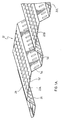
- Figure 1 is a perspective view of a solar heating apparatus according to an embodiment of the present invention;
- Figure 1A is a perspective view of a portion of the solar heating apparatus of Figure 1, drawn to a larger scale;
- Figure 1B is a perspective view of another portion of the solar heating apparatus of Figure 1, drawn to a larger scale;
- Figure 2 is a perspective view of the solar heating apparatus of Figure 1, shown mounted on a roof, with portions of the apparatus missing for illustration and description purposes;
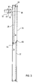
- Figure 3 is a sectional side view of the solar heating apparatus of Figure 1;
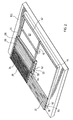
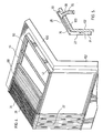
- Figure 4 is a perspective view of a solar heating apparatus according to another embodiment of the present invention, shown mounted to a wall and a roof, with portions of the apparatus missing for the purpose of illustration and description;
- Figure 5 is a sectional side view of the solar heating apparatus of Figure 4, drawn to a smaller scale;
- Figure 6 is a side view of a solar heating apparatus according to another embodiment of the present invention, shown mounted to a roof; and
- Figure 7 is a side view of a solar heating apparatus according to still another embodiment of the present invention, shown mounted to a wall.
-
- Reference is first made to Figures 1 to 3 to describe a solar heating apparatus for pre-heating ventilation air for a building according an embodiment of the present invention, and indicated generally by the numeral 20. The
apparatus 20 includes a first sunlight-absorbent collector panel 22 for locating on the building. Thepanel 22 is exposed to ambient air and defines a firstair collection space 24 between itself and the building. The first sunlight-absorbent collector panel 22 has a plurality ofair inlet openings 26 to allow the ambient air to pass through theopenings 26 to the firstair collection space 24. A second sunlight-absorbent collector panel 28 for locating on the building, adjacent the first sunlight-absorbent collector panel 22, defines a secondair collection space 30 between itself and the building. The second sunlight-absorbent collector panel 28 has a plurality of air inlet openings 32 to allow air to pass through the openings 32 to the secondair collection space 30. Aglazing 34 covers the second sunlight-absorbent collector panel 28 and defines an intermediaryair flow chamber 36 between itself and the second sunlight-absorbent collector panel 28. The intermediaryair flow chamber 36 is in communication with the firstair collection space 24 to receive air therefrom. The air inlet openings 32 in the second sunlight-absorbent collector panel 28 provide communication between the intermediaryair flow chamber 36 and the secondair collection space 30. Anair outlet 38 extends from the secondair collection space 30 into the building for air flow therethrough. Afan 40 communicates with theair outlet 38 for moving air from the secondair collection space 30 into the building, through theair outlet 38. - One embodiment of the
solar heating apparatus 20 will now be further described with reference to the Figures. Referring particularly to Figures 1 to 3, theapparatus 20 is fixed to an outer surface of theroof 100 of the building. As shown in Figures 1 and 2, the first and second sunlight-absorbent collector panels second collector panels roof 100. Theroof 100 is angled such that thefirst collector panel 22 is located at a position on theroof 100 that is below the position of thesecond collector panel 28. - The first and
second collector panels roof 100 of the building in ametal framing structure 42 that includes aperimeter metal frame 44 and an interiorlongitudinal support bar 46. In the present embodiment, thelongitudinal support bar 46 separates the portion of themetal framing structure 42 containing thefirst collector panel 22 and the portion of themetal framing structure 42 containing thesecond collector panel 28. Themetal framing structure 42 including theperimeter metal frame 44 and thelongitudinal support bar 46 is fixed to theroof 100 of the building using suitable fasteners. - The
metal framing structure 42 also includes abacking 50 of metal panels that are secured against theroof 100 of the building, within theperimeter metal frame 44. Thus, thebacking 50 is seated against the surface of theroof 100. - The
perimeter metal frame 44 is sealed to theroof 100 using, for example, silicon caulking. Similarly, the metal panels of thebacking 50 are sealed together and to theperimeter metal frame 44. - The
perimeter metal frame 44 includes a track for receiving edges of the first andsecond collector panels longitudinal support bar 46 also includes tracks for receiving edges of the first andsecond collector panels perimeter metal frame 44. Similarly, the tracks are formed in thelongitudinal support bar 46. - The first collector panel is secured within the
metal framing structure 42 in the tracks of theperimeter metal frame 44 and the track on one side of thelongitudinal support bar 46. It will be noted that thefirst panel 22 includes a number of trapezoidal corrugations that define a plurality of similar and overlapping sub-panels 22a, 22b, 22c... etc. Each of the sub-panels or trapezoidal corrugations 22a, 22b, 22c... etc. includes a flattop portion 52, a pair of slopingside walls 54 and generallyflat gutter walls 56. Each slopingside wall 54 extends from a respective side of the flattop portion 52 and eachgutter wall 56 extends from arespective side wall 54. - The
first collector panel 22 is appropriately secured within themetal framing structure 42 such that eachtop portion 52 of the corrugations is generally parallel with and spaced from thebacking 50. Clearly eachtop portion 52 is also generally parallel with the surface of theroof 100 of the building. Thus, the firstcollection air space 24 is left between thefirst panel 22 and the surface of theroof 100. - As shown in Figure 1A, the
first panel 22 includes theair inlet openings 26 distributed throughout the generally flattop portion 52, the slopingside walls 54 and thegutter walls 56. Theair inlet openings 26 provide openings for the firstair collection space 24 for ambient air to travel from the exterior of the building into the firstair collection space 24. In the present embodiment, theair inlet openings 26 are generally uniformly distributed over the corrugatedfirst collector panel 22 and are formed by rotary punching slits in thefirst collector panel 22 such that the gaps at the end of the slits provide theair inlet openings 26. Theair inlet openings 26 are small to aid in filtering air prior to entry into thesolar heating apparatus 20. - The first collector panel is coated on an exterior side thereof, with a selective coating. The selective coating is a solar radiation absorbing coating for absorbing solar radiation with low infra-red heat radiation emission at temperatures occurring at the collector panel on a sunny day, to keep total energy losses low.
- Like the
first collector panel 22, thesecond collector panel 28 is also secured within themetal framing structure 42, in the tracks of theperimeter metal frame 44 and one side of the track of thelongitudinal support bar 46. Again, thesecond collector panel 28 includes a number of trapezoidal corrugations that define a plurality of similar and overlapping sub-panels 28a, 28b, 28c... etc. Each of the trapezoidal corrugations (sub-panels) includes a generally flattop portion 58, a pair of slopingside walls 60 and a generallyflat gutter wall 62. Each slopingside wall 60 extends from a respective side of the flattop portion 58 and eachgutter wall 62 extends from arespective side wall 60. - Unlike the
first collector panel 22, however, thesecond collector panel 28 is appropriately secured within themetal framing structure 42 such that eachtop portion 58 is not parallel with thebacking 50 and the surface of theroof 100. Instead, eachtop portion 58 lies at an angle with thebacking 50 and thus at an angle with the surface of theroof 100, such that theedge 64 of thesecond collector panel 28 that is closest to thefirst collector panel 22 is adjacent the backing 50 (with a side of the track disposed between theedge 64 of thesecond collector panel 28 and the surface of the roof 100), and theedge 66 of thesecond collector panel 28 that is distal thefirst collector panel 22 is spaced from thebacking 50. Clearly the distance.between thesecond collector panel 28 and thebacking 50 increases with distance from thefirst collector panel 22. Thus, the depth of the secondair collection space 30 increases with distance from thefirst collector panel 22. - Like the
first collector panel 22, thesecond collector panel 28 includes second air inlet openings 32 that are distributed throughout the generally flattop portion 52, the slopingside walls 54 and thegutter walls 56 of the corrugations, as shown in Figure 1 B. The air inlet openings 32 provide openings for the secondair collection space 30. In this case, however, the second air inlet openings 32 provide openings for air to travel from anintermediary flow chamber 36 and into the secondair collection space 30. Clearly the intermediaryair flow chamber 36 is located between the firstair collection space 24 and the secondair collection space 30 with respect to the flow of air, as will be discussed further below. In the present embodiment, the air inlet openings 32 are generally uniformly distributed over thesecond collector panel 28 and are formed by rotary punching slits in thesecond collector panel 28 such that the gaps at the end of the slits provide the air inlet openings 32. - The
second collector panel 28 is also coated on the exterior side thereof with a solar radiation absorbing selective coating for absorbing solar radiation with low infra-red heat radiation emission at temperatures occurring at the collector panel on a sunny day. - A glazing, in the form of
glazing panels 34, is located above and spaced from thesecond collector panel 28. Theglazing panels 34 are fixed to the upper half of theperimeter metal frame 44 and to thelongitudinal support bar 46 using aglazing frame 68 that is fixed to the surface of the upper half of theperimeter metal frame 44 and thelongitudinal support bar 46. It is not necessary for theglazing panels 34 to be sealed in an air-tight manner to theperimeter metal frame 44 and to thelongitudinal support bar 46. A tight fit is sufficient as small air gaps are permissible. - The space between the
glazing panels 34 and thesecond collector panel 28 is the intermediaryair flow chamber 36, referred to above. The intermediaryair flow chamber 36 is in communication with the firstair collection space 24 and with the secondair collection space 30. Air flows into the intermediaryair flow chamber 36 from the firstair collection space 24 and air flows out of the intermediaryair flow chamber 36 to the secondair collection space 30. Clearly thelongitudinal support bar 46 is sized, shaped and located to support ends of the first andsecond collector panels glazing frame 68 which holds theglazing panels 34, while allowing the passage of air from the firstair collection space 24 into the intermediaryair flow chamber 36. In the present embodiment, this air flow is provided by gaps in the track in thelongitudinal support bar 46, through which the air flows. - An
air duct 70 is in communication with the secondair collection space 30, extending through thebacking 50 and passing through theroof 100 of the building. Theair duct 70 is connected to the secondair collection space 30 by theoutlet 38, for air to exit the secondair collection space 30. As shown, theair outlet 38 is located in a position that is distal to thelongitudinal support beam 46, where the distance between thesecond collector panel 28 and thebacking 50 is greatest. - The air duct extends into the building to provide heated outside air to the interior of the building, through openings in the
air duct 70. - A
fan housing 72 is connected along theair duct 70 and includes thefan 40 for moving air from the secondair collection space 30 into the interior of the building. Motorized dampers in thefan housing 72, are adjustable to allow air from the interior of the building to be mixed with heated air coming from the secondair collection space 30. Thefan 40 within thefan housing 72 is typically sized to meet ventilation requirements and to inhibit negative air pressure within the building. A positive air pressure can be achieved by introducing the heated outside air into the building through theair duct 70. Interior air leaves the building through openings and cracks. In the present embodiment, thefan 40 is a variable speed fan that is controlled by a controller dependent on the temperature of the incoming air. Thus, when the incoming air is below room temperature, thefan 40 runs at low speed. When the temperature of the incoming air is above room temperature, the fan speed increases to provide both ventilation air and space heating. - In use, the
solar heating apparatus 20 is located on the exterior of the building, on theroof 100. Ambient air enters the firstair collection space 24 through theair inlet openings 26 of thefirst collector panel 22, where the air is initially heated. Thus, thefirst collector panel 22 acts as an unglazed solar collector. - Next, air passes from the first
air collection space 24 into the intermediaryair flow chamber 36 and through air inlet openings 32 in thesecond collector panel 28, into the secondair collection space 30. The air is further heated as it passes through the intermediaryair flow chamber 36 and the secondair collection space 30. Clearly, thesecond collector panel 28 acts as a glazed solar collector. - Finally, the air is withdrawn from the second
air collection space 30 by thefan 40 and is expelled into the building through theduct 70, to provide heated ventilation air to the building. - Reference is now made to Figures 4 and 5 to describe a
solar heating apparatus 20 according to another embodiment of the present invention. Similar to the first described embodiment, thesolar heating apparatus 20 of the present embodiment includes a first sunlight-absorbent collector panel 22 and a second sunlight-absorbent collector panel 28. Both the first and the second sunlight-absorbent collector panels second collector panels glazing panels 34 are located above and spaced from thesecond collector panel 28. Theglazing panels 34 are similar to the above-described glazing panels and are therefore not further described herein. Unlike the first-described embodiment, however, in the present embodiment, thefirst collector panel 22 is located on awall 102 of the building. Rather than being located on the same wall, thesecond collector panel 28 is located on theroof 100 of the building. Thus, themetal framing structure 42 includes an elbow at a midpoint thereof, where thelongitudinal support bar 46 is located, along the line of intersection of thewall 102 and theroof 100 of the building. The remainder of thesolar heating apparatus 20, including the flow of air therethrough, is similar to thesolar heating apparatus 20 as described above and therefore is not further described herein. - Reference is now made to Figure 6 to describe a
solar heating apparatus 20 according to still another embodiment of the present invention. Rather than thefirst collector panel 22 being corrugated, thefirst collector panel 22 is made up of a number of small overlapping sub-panels, each sub-panel being angled with respect to the surface of theroof 100, as shown. Each sub-panel is closest to theroof 100 of the building at the upper-most portion of the sub-panel. Thus, the space between the sub-panel and the surface of the roof increases from the uppermost to the lowermost portion of each sub-panel. Rather than the air inlet openings 32 being located throughout the corrugated panel, the air inlet openings 32 are located at the lowermost ends of the sub-panels, where the spacing between the sub-panel and the surface of theroof 100 is the greatest. Although thefirst collector panel 22 is shown, it will be understood that the sub-panels as shown can also be used in asecond collector panel 28 that includes aglazing 34 as described above. - Referring to Figure 7, yet another embodiment of the present invention is shown. In this embodiment, the
solar heating apparatus 20 is similar to thesolar heating apparatus 20 shown in Figure 6 and described above. In the present embodiment, however, thesolar heating apparatus 20 is mounted to awall 102 of a building rather than theroof 102. - The present invention has been described by way of examples. Modifications and variations to the above-described embodiments are possible. For example, while the first described embodiment refers to a uniform distribution of
air inlet openings 26 in the first sunlight-absorbent collector panel, the density of air inlet opening in the first sunlight-absorbent collector panel can increase with distance from the second sunlight-absorbent collector panel. Similarly, the density of air openings 32 in the second sunlight-absorbent collector panel can increase with distance from the air outlet. Also, the size of the air inlet openings in the first sunlight-absorbent collector panel can increase with distance from the second sunlight-absorbent collector panel. Similarly, the size of the air inlet openings in the second sunlight-absorbent collector panel can increase with distance from the air outlet. - Other alternatives are also possible. For example, in the above-described embodiments, the tracks were formed in the
longitudinal support bar 46. In an alternative embodiment, the tracks are fastened to thelongitudinal support bar 46. In this case, a number of small track portions or clips are attached to thelongitudinal support bar 46 and spaced apart to allow air flow in between. Similarly, tracks can be fastened to theperimeter metal frame 44, rather than being formed in theperimeter metal frame 44. Also, although theair inlet openings 26 and the air inlet openings 32 are described as being formed by rotary punching slits in the first andsecond collector panels air inlet openings 26 and the air inlet openings 32 are provided by holes punched in the first andsecond collector panels - In yet another variation, both the first and second collector panels can be located on a wall of the building, rather than being located on a roof or on both a wall and a roof of the building. This provides collector panels with corrugations that run in substantially vertical planes, as best shown in Figure 1.
- Still other modifications and variations to the embodiments described herein may occur to those skilled in the art. All such modifications and variations are believed to be within the scope of the present invention.
Claims (19)
- Apparatus (20) for use with a fan for supplying pre-heated ventilation air for a building, the apparatus comprising:a first sunlight-absorbent collector panel (22) on said building, the panel being exposed to ambient air and defining a first air collection space (24) between itself and said building, the first sunlight-absorbent collector panel having a plurality of air inlet openings (26) to allow the ambient air to pass through the openings to the first air collection space;a second sunlight-absorbent collector (28) panel on said building, adjacent said first sunlight-absorbent collector panel, the second sunlight-absorbent collector panel defining a second air collection space (30) between itself and said building, the second sunlight-absorbent collector panel having a plurality of air inlet openings (32) to allow air to pass through the openings to the second air collection space;a glazing (34) covering said second sunlight-absorbent collector panel and defining an intermediary air flow chamber (36) between itself and said second sunlight-absorbent collector panel, said intermediary air flow chamber being in communication with said first air collection space to receive air therefrom, said air inlet openings in said second sunlight-absorbent collector panel providing communication between said intermediary air flow chamber and said second air collection space; andan air outlet (38) from said second air collection space for air flow therethrough for supplying to said building after withdrawal of said pre-heated air by a fan.
- Apparatus as claimed in claim 1, further comprising a fan (40) in communication with said air outlet (38) for moving air from said second air collection space (30) into said building, through said air outlet.
- Apparatus as claimed in claim 2, wherein the fan (40) is able to be controlled at variable speeds depending on temperature of the air withdrawn from the air outlet (38).
- Apparatus as claimed in claim 1, 2 or 3, wherein said first sunlight-absorbent collector panel (22) is corrugated and/or said second sunlight-absorbent collector panel (28) is corrugated.
- Apparatus as claimed in claim 4, wherein said first sunlight-absorbent collector panel (28) is corrugated with corrugations running in substantially vertical planes.
- Apparatus as claimed in any preceding claim, wherein the first sunlight-absorbent collector panel (22) comprises a plurality of substantially similar sub-panels and/or the second sunlight-absorbent collector panel (28) comprises a plurality of substantially similar sub-panels.
- Apparatus as claimed in claim 6, wherein the first sunlight-absorbent collector panel (22) and/or the second sunlight-absorbent collector panel (28) is comprised of a plurality of substantially similar and overlapping sub-panels.
- Apparatus as claimed in any preceding claim, wherein said plurality of air inlet openings (26) are comprised of slits and/or holes in the first sunlight-absorbent collector panel (22) and/or said plurality of air inlet openings (32) are comprised of slits and/or holes in said second sunlight-absorbent collector panel (28).
- Apparatus as claimed in any preceding claim, wherein said first and second sunlight-absorbent collector panels (22, 28) are on a first surface of said building.
- Apparatus as claimed in claim 9, wherein said first sunlight-absorbent collector panel (22) is on a first surface of said building and said second (28) sunlight-absorbent collector panel is on a second surface of said building, adjacent said first surface.
- Apparatus as claimed in any preceding claim, wherein said air inlet openings in said first sunlight-absorbent collector panel are uniformly distributed on said panel.
- Apparatus as claimed in any preceding claim, wherein the density of said air inlet openings (26) in said first sunlight-absorbent collector panel (22) increases with distance from said second sunlight-absorbent collector panel (28) and/or the density of said air inlet openings (32) in said second sunlight-absorbent collector panel increases with distance from said air outlet (38).
- Apparatus as claimed in any preceding claim, wherein the size of said air inlet openings (26) in said first sunlight-absorbent collector panel (22) increases with distance from said second sunlight-absorbent collector panel (28) and/or the size of said air inlet openings (32) in said second sunlight-absorbent collector panel increases with distance from said air output (38).
- Apparatus as claimed in any preceding claim, wherein said first sunlight-absorbent collector panel (22) and/or said second sunlight-absorbent collector panel (28) includes a surface coating on an exterior side thereof, the surface coating permitting high absorption of solar radiation and low emission of far infra-red heat radiation.
- Apparatus as claimed in any preceding claim, wherein second sunlight-absorbent collector panel (28) is located above said first sunlight-absorbent collector panel (22).
- Apparatus as claimed in any preceding claim, wherein said first sunlight-absorbent collector panel (22) is located on a substantially vertical surface of said building.
- Apparatus as claimed in claim 16, wherein said second sunlight-absorbent collector panel (28) is located on said substantially vertical surface of said building or is located on a roof (100) of said building.
- A method of heating ventilation air for a building, comprising:providing apparatus (20) as claimed in any preceding claim;pre-heating outside air in the first air collection space (24), with solar heat from the first sunlight-absorbent collector panel (22) and passing the pre-heated air into the intermediary flow chamber (36);heating the pre-heated air in the second air collection space (30) by passing the pre-heated air from the intermediary flow chamber into the second air collection space, to provide heated air;withdrawing said heated air through the air outlet (38) from said second air collection space and expelling said air into said building.
- A method as claimed in claim 18, wherein pre-heating the outside air comprises removing heat from substantially an entire surface of said first sunlight-absorbent collector panel (22) and/or from substantially an entire surface of said second sunlight-absorbent collector panel (28).
Priority Applications (1)
| Application Number | Priority Date | Filing Date | Title |
|---|---|---|---|
| PL05252918T PL1596138T3 (en) | 2004-05-14 | 2005-05-12 | Method and apparatus for preheating ventilation air for a building |
Applications Claiming Priority (2)
| Application Number | Priority Date | Filing Date | Title |
|---|---|---|---|
| US10/846,112 US7032588B2 (en) | 2004-05-14 | 2004-05-14 | Method and apparatus for preheating ventilation air for a building |
| US846112 | 2004-05-14 |
Publications (3)
| Publication Number | Publication Date |
|---|---|
| EP1596138A2 true EP1596138A2 (en) | 2005-11-16 |
| EP1596138A3 EP1596138A3 (en) | 2007-05-23 |
| EP1596138B1 EP1596138B1 (en) | 2010-10-06 |
Family
ID=34941265
Family Applications (1)
| Application Number | Title | Priority Date | Filing Date |
|---|---|---|---|
| EP05252918A Active EP1596138B1 (en) | 2004-05-14 | 2005-05-12 | Method and apparatus for preheating ventilation air for a building |
Country Status (11)
| Country | Link |
|---|---|
| US (1) | US7032588B2 (en) |
| EP (1) | EP1596138B1 (en) |
| JP (1) | JP4676808B2 (en) |
| CN (1) | CN100572974C (en) |
| AT (1) | ATE483944T1 (en) |
| CA (1) | CA2503395C (en) |
| DE (1) | DE602005023935D1 (en) |
| DK (1) | DK1596138T3 (en) |
| ES (1) | ES2356183T3 (en) |
| PL (1) | PL1596138T3 (en) |
| PT (1) | PT1596138E (en) |
Cited By (7)
| Publication number | Priority date | Publication date | Assignee | Title |
|---|---|---|---|---|
| DE102005058887A1 (en) * | 2005-12-09 | 2007-06-14 | Stys, Antoni Slawomir, Dipl.-Ing. | Solar heating system for building with blown airflow to heat rooms or warm water supply |
| FR2929379A1 (en) * | 2008-04-01 | 2009-10-02 | Opaly Soc Par Actions Simplifi | Hollow panel for fabricating wall of building, has fluid circulation channel extending between receiver and perforated receiver that is exposed to heat radiation and transform radiation by reflection, transmission and/or absorption |
| WO2009125159A3 (en) * | 2008-04-01 | 2010-08-19 | OPALY, Société par actions simplifiée | Method and device for trimming for facade or roof of a building |
| NL1036649C2 (en) * | 2009-03-02 | 2010-09-03 | Luijten Smeulders Architecten B V | BUILDING WITH ENERGY PRODUCTION PRODUCTS. |
| EP2245380A1 (en) * | 2008-02-07 | 2010-11-03 | Soltech Energy Sweden Ab | Solar energy system |
| WO2010082908A3 (en) * | 2009-01-13 | 2011-01-06 | Gökser Maki̇na Sanayi̇ Ti̇c Ltd Şti̇ | Hybrid food drying system |
| NL2011550C2 (en) * | 2013-10-03 | 2015-04-07 | Unda Maris Holding N V | WALL SYSTEM, FACADE PANEL THEREFORE, AND THE BUILDING PROVIDED FOR THIS. |
Families Citing this family (20)
| Publication number | Priority date | Publication date | Assignee | Title |
|---|---|---|---|---|
| US9574783B2 (en) | 2006-05-18 | 2017-02-21 | Hollick Solar Systems Limited | Method and apparatus for two stage cooling of ambient air |
| US8827779B2 (en) * | 2006-05-18 | 2014-09-09 | Hollick Solar Systems Limited | Method and apparatus for cooling ventilation air for a building |
| CA2559641C (en) * | 2006-09-13 | 2014-04-15 | Matrix Energy Inc. | Solar air heating system |
| US7677243B2 (en) | 2007-01-22 | 2010-03-16 | Wal-Mart Stores, Inc. | Solar heating system and architectural structure with a solar heating system |
| US20100186734A1 (en) * | 2007-02-05 | 2010-07-29 | Paul Riis Arndt | Solar air heater for heating air flow |
| IE86172B1 (en) | 2007-05-01 | 2013-04-10 | Kingspan Res & Dev Ltd | A composite insulating panel having a heat exchange conduit means |
| CA2638257C (en) * | 2007-07-26 | 2013-04-09 | Enerconcept Technologies Inc. | Perforated transparent glazing for heat recovery and solar air heating |
| EP2315980A4 (en) * | 2008-07-29 | 2015-05-06 | Syenergy Integrated Energy Solutions Inc | Curved transpired solar air heater and conduit |
| JP2010096457A (en) * | 2008-10-17 | 2010-04-30 | Nippon Light Metal Co Ltd | Air conditioning device |
| US8371073B2 (en) * | 2010-03-04 | 2013-02-12 | Michael Fuller Architects, Pc | Building with integrated natural systems |
| US8555872B2 (en) | 2011-03-04 | 2013-10-15 | John Allan Dolphin | Solar heater |
| CN102226586A (en) * | 2011-04-20 | 2011-10-26 | 上海福奥建筑科技有限公司 | Solar flat type heat collector and heat collection plate thereof |
| US20130118478A1 (en) * | 2011-11-11 | 2013-05-16 | Masdar Institute Of Science And Technology | Liquid-air transpired solar collectors |
| EP2904334B1 (en) * | 2012-10-02 | 2018-10-03 | Solarjoule IP Holdings Limited | Solar air heating / cooling system |
| US9664396B2 (en) * | 2012-11-08 | 2017-05-30 | Iis Institute For Independent Studies Gmbh | Building envelope and method for adjusting the temperature in a building |
| GB2526269B (en) * | 2014-05-16 | 2018-09-12 | Solar Frame Solutions Ltd | Solar-collector roofing assembly |
| GB2540384B (en) * | 2015-07-15 | 2020-04-29 | Energy Transitions Ltd | Transpired solar collector |
| CN105865042B (en) * | 2016-06-08 | 2017-12-05 | 日出东方太阳能股份有限公司 | A kind of solar air heater and heating means |
| CN110500774B (en) * | 2019-08-22 | 2021-06-04 | 沂源县源能热力有限公司 | Heating system with regulatory function |
| PL3988859T3 (en) | 2020-10-26 | 2023-05-15 | Almeco Gmbh | Deformable composite material for uncovered solar energy absorbent collector panels with low infrared radiation losses |
Citations (10)
| Publication number | Priority date | Publication date | Assignee | Title |
|---|---|---|---|---|
| US4090494A (en) * | 1977-01-24 | 1978-05-23 | Southern Illinois University Foundation | Solar collector |
| US4143815A (en) * | 1975-10-22 | 1979-03-13 | Energietechnik Gmbh | Heating apparatus |
| FR2469674A1 (en) * | 1979-11-15 | 1981-05-22 | Omnium Fs Indl Cal | Solar energy trap with absorbent bodies of corrugated bitumastic board - to smooth variations in the rate of energy capture |
| FR2491599A1 (en) * | 1980-10-08 | 1982-04-09 | Olivier Gilbert | Solar heating panel using air as working fluid - has forced air circulation through triangular section chambers defined by absorber panels |
| NL8102154A (en) * | 1981-05-01 | 1982-12-01 | Drs Hendrik Jan Dorrestijn | Roof mounted solar heat collector - has surface of flat porous highly light absorbent material |
| FR2535444A1 (en) * | 1982-10-29 | 1984-05-04 | Dalmas Ets | Solar collector using air. |
| US4899728A (en) * | 1989-01-27 | 1990-02-13 | Solarwall International Limited | Method and apparatus for preheating ventilation air for a building |
| JPH06281261A (en) * | 1993-03-31 | 1994-10-07 | Gantan Beauty Kogyo Kk | Device for collecting solar heat |
| DE19505918A1 (en) * | 1995-02-21 | 1996-08-22 | Karlfried Cost | Solar collector for heating air |
| US5692491A (en) * | 1996-04-19 | 1997-12-02 | Midwest Research Institute | Unglazed transpired solar collector having a low thermal-conductance absorber |
Family Cites Families (8)
| Publication number | Priority date | Publication date | Assignee | Title |
|---|---|---|---|---|
| JPS499492B1 (en) * | 1970-12-22 | 1974-03-05 | ||
| US4478210A (en) * | 1979-04-16 | 1984-10-23 | Sieradski Leonard M | Solar heating system |
| CA1196825A (en) | 1982-05-04 | 1985-11-19 | John C. Hollick | Method for preheating ventilation air in a building |
| CA1283333C (en) | 1988-02-11 | 1991-04-23 | John Carl Hollick | Method and apparatus for preheating ventilation air for a building |
| JPH04136660A (en) * | 1990-09-26 | 1992-05-11 | Yoshitomi Takeda | Solar system |
| US5596981A (en) * | 1993-07-19 | 1997-01-28 | Soucy; Paul B. | Solar device and method for assembly |
| CA2230471C (en) | 1998-02-25 | 2001-09-11 | John Carl Hollick | Combined solar collector and photovoltaic cells |
| US5935343A (en) | 1998-03-13 | 1999-08-10 | Hollick; John Carl | Combined solar collector and photovoltaic cells |
-
2004
- 2004-05-14 US US10/846,112 patent/US7032588B2/en active Active
-
2005
- 2005-04-01 CA CA002503395A patent/CA2503395C/en active Active
- 2005-04-21 JP JP2005124287A patent/JP4676808B2/en not_active Expired - Fee Related
- 2005-05-11 CN CNB2005100725420A patent/CN100572974C/en active Active
- 2005-05-12 AT AT05252918T patent/ATE483944T1/en not_active IP Right Cessation
- 2005-05-12 EP EP05252918A patent/EP1596138B1/en active Active
- 2005-05-12 DE DE602005023935T patent/DE602005023935D1/en active Active
- 2005-05-12 ES ES05252918T patent/ES2356183T3/en active Active
- 2005-05-12 PT PT05252918T patent/PT1596138E/en unknown
- 2005-05-12 PL PL05252918T patent/PL1596138T3/en unknown
- 2005-05-12 DK DK05252918.7T patent/DK1596138T3/en active
Patent Citations (10)
| Publication number | Priority date | Publication date | Assignee | Title |
|---|---|---|---|---|
| US4143815A (en) * | 1975-10-22 | 1979-03-13 | Energietechnik Gmbh | Heating apparatus |
| US4090494A (en) * | 1977-01-24 | 1978-05-23 | Southern Illinois University Foundation | Solar collector |
| FR2469674A1 (en) * | 1979-11-15 | 1981-05-22 | Omnium Fs Indl Cal | Solar energy trap with absorbent bodies of corrugated bitumastic board - to smooth variations in the rate of energy capture |
| FR2491599A1 (en) * | 1980-10-08 | 1982-04-09 | Olivier Gilbert | Solar heating panel using air as working fluid - has forced air circulation through triangular section chambers defined by absorber panels |
| NL8102154A (en) * | 1981-05-01 | 1982-12-01 | Drs Hendrik Jan Dorrestijn | Roof mounted solar heat collector - has surface of flat porous highly light absorbent material |
| FR2535444A1 (en) * | 1982-10-29 | 1984-05-04 | Dalmas Ets | Solar collector using air. |
| US4899728A (en) * | 1989-01-27 | 1990-02-13 | Solarwall International Limited | Method and apparatus for preheating ventilation air for a building |
| JPH06281261A (en) * | 1993-03-31 | 1994-10-07 | Gantan Beauty Kogyo Kk | Device for collecting solar heat |
| DE19505918A1 (en) * | 1995-02-21 | 1996-08-22 | Karlfried Cost | Solar collector for heating air |
| US5692491A (en) * | 1996-04-19 | 1997-12-02 | Midwest Research Institute | Unglazed transpired solar collector having a low thermal-conductance absorber |
Cited By (8)
| Publication number | Priority date | Publication date | Assignee | Title |
|---|---|---|---|---|
| DE102005058887A1 (en) * | 2005-12-09 | 2007-06-14 | Stys, Antoni Slawomir, Dipl.-Ing. | Solar heating system for building with blown airflow to heat rooms or warm water supply |
| EP2245380A1 (en) * | 2008-02-07 | 2010-11-03 | Soltech Energy Sweden Ab | Solar energy system |
| EP2245380A4 (en) * | 2008-02-07 | 2014-01-01 | Soltech Energy Sweden Ab | Solar energy system |
| FR2929379A1 (en) * | 2008-04-01 | 2009-10-02 | Opaly Soc Par Actions Simplifi | Hollow panel for fabricating wall of building, has fluid circulation channel extending between receiver and perforated receiver that is exposed to heat radiation and transform radiation by reflection, transmission and/or absorption |
| WO2009125159A3 (en) * | 2008-04-01 | 2010-08-19 | OPALY, Société par actions simplifiée | Method and device for trimming for facade or roof of a building |
| WO2010082908A3 (en) * | 2009-01-13 | 2011-01-06 | Gökser Maki̇na Sanayi̇ Ti̇c Ltd Şti̇ | Hybrid food drying system |
| NL1036649C2 (en) * | 2009-03-02 | 2010-09-03 | Luijten Smeulders Architecten B V | BUILDING WITH ENERGY PRODUCTION PRODUCTS. |
| NL2011550C2 (en) * | 2013-10-03 | 2015-04-07 | Unda Maris Holding N V | WALL SYSTEM, FACADE PANEL THEREFORE, AND THE BUILDING PROVIDED FOR THIS. |
Also Published As
| Publication number | Publication date |
|---|---|
| US7032588B2 (en) | 2006-04-25 |
| CN1760601A (en) | 2006-04-19 |
| EP1596138B1 (en) | 2010-10-06 |
| PT1596138E (en) | 2011-01-14 |
| CA2503395C (en) | 2007-01-09 |
| CN100572974C (en) | 2009-12-23 |
| US20050252507A1 (en) | 2005-11-17 |
| ATE483944T1 (en) | 2010-10-15 |
| DK1596138T3 (en) | 2011-01-31 |
| DE602005023935D1 (en) | 2010-11-18 |
| ES2356183T3 (en) | 2011-04-05 |
| EP1596138A3 (en) | 2007-05-23 |
| JP4676808B2 (en) | 2011-04-27 |
| PL1596138T3 (en) | 2011-03-31 |
| CA2503395A1 (en) | 2005-11-14 |
| JP2005326142A (en) | 2005-11-24 |
Similar Documents
| Publication | Publication Date | Title |
|---|---|---|
| EP1596138B1 (en) | Method and apparatus for preheating ventilation air for a building | |
| EP0380349B1 (en) | Improved method and apparatus for preheating ventilation air for a building | |
| EP2021701B1 (en) | Method and apparatus for cooling ventilation air for a building | |
| US8276580B2 (en) | Modular transpired solar air collector | |
| JP2675385B2 (en) | Method and apparatus for preheating ventilation air | |
| CA2559641C (en) | Solar air heating system | |
| US20210302030A1 (en) | Commercial building solar heating system | |
| CN101059279B (en) | Air type solar energy heat-collecting ventilation system | |
| JP2649906B2 (en) | Solar heat collector | |
| JP2846913B2 (en) | Building air preheating method and apparatus | |
| JP4541372B2 (en) | Pneumatic solar collector ventilation system | |
| JPS58214745A (en) | Room heating apparatus utilizing solar heat | |
| DE4334191A1 (en) | Building with air-conditioning system |
Legal Events
| Date | Code | Title | Description |
|---|---|---|---|
| PUAI | Public reference made under article 153(3) epc to a published international application that has entered the european phase |
Free format text: ORIGINAL CODE: 0009012 |
|
| AK | Designated contracting states |
Kind code of ref document: A2 Designated state(s): AT BE BG CH CY CZ DE DK EE ES FI FR GB GR HU IE IS IT LI LT LU MC NL PL PT RO SE SI SK TR |
|
| AX | Request for extension of the european patent |
Extension state: AL BA HR LV MK YU |
|
| PUAL | Search report despatched |
Free format text: ORIGINAL CODE: 0009013 |
|
| AK | Designated contracting states |
Kind code of ref document: A3 Designated state(s): AT BE BG CH CY CZ DE DK EE ES FI FR GB GR HU IE IS IT LI LT LU MC NL PL PT RO SE SI SK TR |
|
| AX | Request for extension of the european patent |
Extension state: AL BA HR LV MK YU |
|
| 17P | Request for examination filed |
Effective date: 20071119 |
|
| AKX | Designation fees paid |
Designated state(s): AT BE BG CH CY CZ DE DK EE ES FI FR GB GR HU IE IS IT LI LT LU MC NL PL PT RO SE SI SK TR |
|
| GRAP | Despatch of communication of intention to grant a patent |
Free format text: ORIGINAL CODE: EPIDOSNIGR1 |
|
| GRAS | Grant fee paid |
Free format text: ORIGINAL CODE: EPIDOSNIGR3 |
|
| GRAA | (expected) grant |
Free format text: ORIGINAL CODE: 0009210 |
|
| AK | Designated contracting states |
Kind code of ref document: B1 Designated state(s): AT BE BG CH CY CZ DE DK EE ES FI FR GB GR HU IE IS IT LI LT LU MC NL PL PT RO SE SI SK TR |
|
| REG | Reference to a national code |
Ref country code: GB Ref legal event code: FG4D |
|
| REG | Reference to a national code |
Ref country code: CH Ref legal event code: EP |
|
| REG | Reference to a national code |
Ref country code: IE Ref legal event code: FG4D |
|
| REF | Corresponds to: |
Ref document number: 602005023935 Country of ref document: DE Date of ref document: 20101118 Kind code of ref document: P |
|
| REG | Reference to a national code |
Ref country code: NL Ref legal event code: T3 |
|
| REG | Reference to a national code |
Ref country code: PT Ref legal event code: SC4A Free format text: AVAILABILITY OF NATIONAL TRANSLATION Effective date: 20110104 |
|
| REG | Reference to a national code |
Ref country code: SE Ref legal event code: TRGR |
|
| REG | Reference to a national code |
Ref country code: DK Ref legal event code: T3 |
|
| PG25 | Lapsed in a contracting state [announced via postgrant information from national office to epo] |
Ref country code: SI Free format text: LAPSE BECAUSE OF FAILURE TO SUBMIT A TRANSLATION OF THE DESCRIPTION OR TO PAY THE FEE WITHIN THE PRESCRIBED TIME-LIMIT Effective date: 20101006 |
|
| LTIE | Lt: invalidation of european patent or patent extension |
Effective date: 20101006 |
|
| REG | Reference to a national code |
Ref country code: PL Ref legal event code: T3 |
|
| REG | Reference to a national code |
Ref country code: ES Ref legal event code: FG2A Ref document number: 2356183 Country of ref document: ES Kind code of ref document: T3 Effective date: 20110405 |
|
| PG25 | Lapsed in a contracting state [announced via postgrant information from national office to epo] |
Ref country code: LT Free format text: LAPSE BECAUSE OF FAILURE TO SUBMIT A TRANSLATION OF THE DESCRIPTION OR TO PAY THE FEE WITHIN THE PRESCRIBED TIME-LIMIT Effective date: 20101006 |
|
| PG25 | Lapsed in a contracting state [announced via postgrant information from national office to epo] |
Ref country code: BG Free format text: LAPSE BECAUSE OF FAILURE TO SUBMIT A TRANSLATION OF THE DESCRIPTION OR TO PAY THE FEE WITHIN THE PRESCRIBED TIME-LIMIT Effective date: 20110106 Ref country code: IS Free format text: LAPSE BECAUSE OF FAILURE TO SUBMIT A TRANSLATION OF THE DESCRIPTION OR TO PAY THE FEE WITHIN THE PRESCRIBED TIME-LIMIT Effective date: 20110206 Ref country code: AT Free format text: LAPSE BECAUSE OF FAILURE TO SUBMIT A TRANSLATION OF THE DESCRIPTION OR TO PAY THE FEE WITHIN THE PRESCRIBED TIME-LIMIT Effective date: 20101006 Ref country code: FI Free format text: LAPSE BECAUSE OF FAILURE TO SUBMIT A TRANSLATION OF THE DESCRIPTION OR TO PAY THE FEE WITHIN THE PRESCRIBED TIME-LIMIT Effective date: 20101006 |
|
| PG25 | Lapsed in a contracting state [announced via postgrant information from national office to epo] |
Ref country code: GR Free format text: LAPSE BECAUSE OF FAILURE TO SUBMIT A TRANSLATION OF THE DESCRIPTION OR TO PAY THE FEE WITHIN THE PRESCRIBED TIME-LIMIT Effective date: 20110107 |
|
| PG25 | Lapsed in a contracting state [announced via postgrant information from national office to epo] |
Ref country code: EE Free format text: LAPSE BECAUSE OF FAILURE TO SUBMIT A TRANSLATION OF THE DESCRIPTION OR TO PAY THE FEE WITHIN THE PRESCRIBED TIME-LIMIT Effective date: 20101006 Ref country code: CZ Free format text: LAPSE BECAUSE OF FAILURE TO SUBMIT A TRANSLATION OF THE DESCRIPTION OR TO PAY THE FEE WITHIN THE PRESCRIBED TIME-LIMIT Effective date: 20101006 |
|
| PLBE | No opposition filed within time limit |
Free format text: ORIGINAL CODE: 0009261 |
|
| STAA | Information on the status of an ep patent application or granted ep patent |
Free format text: STATUS: NO OPPOSITION FILED WITHIN TIME LIMIT |
|
| PG25 | Lapsed in a contracting state [announced via postgrant information from national office to epo] |
Ref country code: RO Free format text: LAPSE BECAUSE OF FAILURE TO SUBMIT A TRANSLATION OF THE DESCRIPTION OR TO PAY THE FEE WITHIN THE PRESCRIBED TIME-LIMIT Effective date: 20101006 Ref country code: SK Free format text: LAPSE BECAUSE OF FAILURE TO SUBMIT A TRANSLATION OF THE DESCRIPTION OR TO PAY THE FEE WITHIN THE PRESCRIBED TIME-LIMIT Effective date: 20101006 |
|
| 26N | No opposition filed |
Effective date: 20110707 |
|
| REG | Reference to a national code |
Ref country code: HU Ref legal event code: AG4A Ref document number: E010838 Country of ref document: HU |
|
| REG | Reference to a national code |
Ref country code: DE Ref legal event code: R097 Ref document number: 602005023935 Country of ref document: DE Effective date: 20110707 |
|
| PG25 | Lapsed in a contracting state [announced via postgrant information from national office to epo] |
Ref country code: MC Free format text: LAPSE BECAUSE OF NON-PAYMENT OF DUE FEES Effective date: 20110531 |
|
| PG25 | Lapsed in a contracting state [announced via postgrant information from national office to epo] |
Ref country code: LU Free format text: LAPSE BECAUSE OF NON-PAYMENT OF DUE FEES Effective date: 20110512 Ref country code: CY Free format text: LAPSE BECAUSE OF FAILURE TO SUBMIT A TRANSLATION OF THE DESCRIPTION OR TO PAY THE FEE WITHIN THE PRESCRIBED TIME-LIMIT Effective date: 20101006 |
|
| PGFP | Annual fee paid to national office [announced via postgrant information from national office to epo] |
Ref country code: HU Payment date: 20130510 Year of fee payment: 9 |
|
| PGFP | Annual fee paid to national office [announced via postgrant information from national office to epo] |
Ref country code: PT Payment date: 20140505 Year of fee payment: 10 |
|
| PG25 | Lapsed in a contracting state [announced via postgrant information from national office to epo] |
Ref country code: HU Free format text: LAPSE BECAUSE OF NON-PAYMENT OF DUE FEES Effective date: 20140513 |
|
| PGFP | Annual fee paid to national office [announced via postgrant information from national office to epo] |
Ref country code: CH Payment date: 20150527 Year of fee payment: 11 |
|
| REG | Reference to a national code |
Ref country code: PT Ref legal event code: MM4A Free format text: LAPSE DUE TO NON-PAYMENT OF FEES Effective date: 20151112 |
|
| PG25 | Lapsed in a contracting state [announced via postgrant information from national office to epo] |
Ref country code: PT Free format text: LAPSE BECAUSE OF NON-PAYMENT OF DUE FEES Effective date: 20151112 |
|
| REG | Reference to a national code |
Ref country code: FR Ref legal event code: PLFP Year of fee payment: 12 |
|
| PGFP | Annual fee paid to national office [announced via postgrant information from national office to epo] |
Ref country code: NL Payment date: 20160516 Year of fee payment: 12 |
|
| PGFP | Annual fee paid to national office [announced via postgrant information from national office to epo] |
Ref country code: BE Payment date: 20160523 Year of fee payment: 12 Ref country code: DK Payment date: 20160523 Year of fee payment: 12 |
|
| REG | Reference to a national code |
Ref country code: CH Ref legal event code: PL |
|
| PG25 | Lapsed in a contracting state [announced via postgrant information from national office to epo] |
Ref country code: CH Free format text: LAPSE BECAUSE OF NON-PAYMENT OF DUE FEES Effective date: 20160531 Ref country code: LI Free format text: LAPSE BECAUSE OF NON-PAYMENT OF DUE FEES Effective date: 20160531 |
|
| REG | Reference to a national code |
Ref country code: FR Ref legal event code: PLFP Year of fee payment: 13 |
|
| REG | Reference to a national code |
Ref country code: DE Ref legal event code: R079 Ref document number: 602005023935 Country of ref document: DE Free format text: PREVIOUS MAIN CLASS: F24J0002040000 Ipc: F24S0010000000 |
|
| REG | Reference to a national code |
Ref country code: DK Ref legal event code: EBP Effective date: 20170531 |
|
| REG | Reference to a national code |
Ref country code: NL Ref legal event code: MM Effective date: 20170601 |
|
| PG25 | Lapsed in a contracting state [announced via postgrant information from national office to epo] |
Ref country code: NL Free format text: LAPSE BECAUSE OF NON-PAYMENT OF DUE FEES Effective date: 20170601 |
|
| REG | Reference to a national code |
Ref country code: BE Ref legal event code: MM Effective date: 20170531 |
|
| PG25 | Lapsed in a contracting state [announced via postgrant information from national office to epo] |
Ref country code: DK Free format text: LAPSE BECAUSE OF NON-PAYMENT OF DUE FEES Effective date: 20170531 |
|
| REG | Reference to a national code |
Ref country code: FR Ref legal event code: PLFP Year of fee payment: 14 |
|
| PG25 | Lapsed in a contracting state [announced via postgrant information from national office to epo] |
Ref country code: BE Free format text: LAPSE BECAUSE OF NON-PAYMENT OF DUE FEES Effective date: 20170531 |
|
| REG | Reference to a national code |
Ref country code: IE Ref legal event code: MM4A |
|
| PG25 | Lapsed in a contracting state [announced via postgrant information from national office to epo] |
Ref country code: IE Free format text: LAPSE BECAUSE OF NON-PAYMENT OF DUE FEES Effective date: 20180512 |
|
| REG | Reference to a national code |
Ref country code: DE Ref legal event code: R119 Ref document number: 602005023935 Country of ref document: DE |
|
| PG25 | Lapsed in a contracting state [announced via postgrant information from national office to epo] |
Ref country code: SE Free format text: LAPSE BECAUSE OF NON-PAYMENT OF DUE FEES Effective date: 20200513 |
|
| PG25 | Lapsed in a contracting state [announced via postgrant information from national office to epo] |
Ref country code: DE Free format text: LAPSE BECAUSE OF NON-PAYMENT OF DUE FEES Effective date: 20201201 |
|
| PGFP | Annual fee paid to national office [announced via postgrant information from national office to epo] |
Ref country code: IT Payment date: 20220531 Year of fee payment: 18 |
|
| PG25 | Lapsed in a contracting state [announced via postgrant information from national office to epo] |
Ref country code: PL Free format text: LAPSE BECAUSE OF NON-PAYMENT OF DUE FEES Effective date: 20200512 |
|
| PGFP | Annual fee paid to national office [announced via postgrant information from national office to epo] |
Ref country code: FR Payment date: 20230517 Year of fee payment: 19 Ref country code: ES Payment date: 20230621 Year of fee payment: 19 |
|
| PGFP | Annual fee paid to national office [announced via postgrant information from national office to epo] |
Ref country code: TR Payment date: 20230414 Year of fee payment: 19 |
|
| PGFP | Annual fee paid to national office [announced via postgrant information from national office to epo] |
Ref country code: GB Payment date: 20230412 Year of fee payment: 19 |