EP2146383A2 - Building integrated photovoltaic (BIPV) junction box - Google Patents
Building integrated photovoltaic (BIPV) junction box Download PDFInfo
- Publication number
- EP2146383A2 EP2146383A2 EP09009176A EP09009176A EP2146383A2 EP 2146383 A2 EP2146383 A2 EP 2146383A2 EP 09009176 A EP09009176 A EP 09009176A EP 09009176 A EP09009176 A EP 09009176A EP 2146383 A2 EP2146383 A2 EP 2146383A2
- Authority
- EP
- European Patent Office
- Prior art keywords
- junction box
- sidewalls
- housing
- solar cell
- connection assembly
- Prior art date
- Legal status (The legal status is an assumption and is not a legal conclusion. Google has not performed a legal analysis and makes no representation as to the accuracy of the status listed.)
- Withdrawn
Links
- 238000000429 assembly Methods 0.000 claims description 15
- 230000004224 protection Effects 0.000 claims description 4
- 230000000712 assembly Effects 0.000 description 11
- 239000011521 glass Substances 0.000 description 8
- 230000000903 blocking effect Effects 0.000 description 6
- 238000010276 construction Methods 0.000 description 5
- 238000005516 engineering process Methods 0.000 description 4
- 238000009434 installation Methods 0.000 description 4
- 238000007789 sealing Methods 0.000 description 4
- 239000000853 adhesive Substances 0.000 description 3
- 230000001070 adhesive effect Effects 0.000 description 3
- VYPSYNLAJGMNEJ-UHFFFAOYSA-N Silicium dioxide Chemical compound O=[Si]=O VYPSYNLAJGMNEJ-UHFFFAOYSA-N 0.000 description 2
- 239000011810 insulating material Substances 0.000 description 2
- 230000003252 repetitive effect Effects 0.000 description 2
- 239000000741 silica gel Substances 0.000 description 2
- 229910002027 silica gel Inorganic materials 0.000 description 2
- 239000004020 conductor Substances 0.000 description 1
- 230000002542 deteriorative effect Effects 0.000 description 1
- 230000000694 effects Effects 0.000 description 1
- 230000005611 electricity Effects 0.000 description 1
- 238000003780 insertion Methods 0.000 description 1
- 230000037431 insertion Effects 0.000 description 1
- 238000002955 isolation Methods 0.000 description 1
- 238000004519 manufacturing process Methods 0.000 description 1
- 239000002184 metal Substances 0.000 description 1
- 239000000565 sealant Substances 0.000 description 1
- 239000012945 sealing adhesive Substances 0.000 description 1
- 125000006850 spacer group Chemical group 0.000 description 1
Images


Classifications
-
- H—ELECTRICITY
- H02—GENERATION; CONVERSION OR DISTRIBUTION OF ELECTRIC POWER
- H02G—INSTALLATION OF ELECTRIC CABLES OR LINES, OR OF COMBINED OPTICAL AND ELECTRIC CABLES OR LINES
- H02G3/00—Installations of electric cables or lines or protective tubing therefor in or on buildings, equivalent structures or vehicles
- H02G3/02—Details
- H02G3/08—Distribution boxes; Connection or junction boxes
- H02G3/088—Dustproof, splashproof, drip-proof, waterproof, or flameproof casings or inlets
-
- H—ELECTRICITY
- H02—GENERATION; CONVERSION OR DISTRIBUTION OF ELECTRIC POWER
- H02S—GENERATION OF ELECTRIC POWER BY CONVERSION OF INFRARED RADIATION, VISIBLE LIGHT OR ULTRAVIOLET LIGHT, e.g. USING PHOTOVOLTAIC [PV] MODULES
- H02S40/00—Components or accessories in combination with PV modules, not provided for in groups H02S10/00 - H02S30/00
- H02S40/30—Electrical components
- H02S40/34—Electrical components comprising specially adapted electrical connection means to be structurally associated with the PV module, e.g. junction boxes
-
- H—ELECTRICITY
- H01—ELECTRIC ELEMENTS
- H01R—ELECTRICALLY-CONDUCTIVE CONNECTIONS; STRUCTURAL ASSOCIATIONS OF A PLURALITY OF MUTUALLY-INSULATED ELECTRICAL CONNECTING ELEMENTS; COUPLING DEVICES; CURRENT COLLECTORS
- H01R4/00—Electrically-conductive connections between two or more conductive members in direct contact, i.e. touching one another; Means for effecting or maintaining such contact; Electrically-conductive connections having two or more spaced connecting locations for conductors and using contact members penetrating insulation
- H01R4/28—Clamped connections, spring connections
- H01R4/48—Clamped connections, spring connections utilising a spring, clip, or other resilient member
- H01R4/4809—Clamped connections, spring connections utilising a spring, clip, or other resilient member using a leaf spring to bias the conductor toward the busbar
- H01R4/48185—Clamped connections, spring connections utilising a spring, clip, or other resilient member using a leaf spring to bias the conductor toward the busbar adapted for axial insertion of a wire end
- H01R4/48275—Clamped connections, spring connections utilising a spring, clip, or other resilient member using a leaf spring to bias the conductor toward the busbar adapted for axial insertion of a wire end with an opening in the housing for insertion of a release tool
-
- H—ELECTRICITY
- H02—GENERATION; CONVERSION OR DISTRIBUTION OF ELECTRIC POWER
- H02G—INSTALLATION OF ELECTRIC CABLES OR LINES, OR OF COMBINED OPTICAL AND ELECTRIC CABLES OR LINES
- H02G3/00—Installations of electric cables or lines or protective tubing therefor in or on buildings, equivalent structures or vehicles
- H02G3/02—Details
- H02G3/06—Joints for connecting lengths of protective tubing or channels, to each other or to casings, e.g. to distribution boxes; Ensuring electrical continuity in the joint
- H02G3/0616—Joints for connecting tubing to casing
- H02G3/0625—Joints for connecting tubing to casing with means for preventing disengagement of conductors
- H02G3/0675—Joints for connecting tubing to casing with means for preventing disengagement of conductors with bolts operating in a direction parallel to the conductors
-
- Y—GENERAL TAGGING OF NEW TECHNOLOGICAL DEVELOPMENTS; GENERAL TAGGING OF CROSS-SECTIONAL TECHNOLOGIES SPANNING OVER SEVERAL SECTIONS OF THE IPC; TECHNICAL SUBJECTS COVERED BY FORMER USPC CROSS-REFERENCE ART COLLECTIONS [XRACs] AND DIGESTS
- Y02—TECHNOLOGIES OR APPLICATIONS FOR MITIGATION OR ADAPTATION AGAINST CLIMATE CHANGE
- Y02A—TECHNOLOGIES FOR ADAPTATION TO CLIMATE CHANGE
- Y02A30/00—Adapting or protecting infrastructure or their operation
- Y02A30/60—Planning or developing urban green infrastructure
-
- Y—GENERAL TAGGING OF NEW TECHNOLOGICAL DEVELOPMENTS; GENERAL TAGGING OF CROSS-SECTIONAL TECHNOLOGIES SPANNING OVER SEVERAL SECTIONS OF THE IPC; TECHNICAL SUBJECTS COVERED BY FORMER USPC CROSS-REFERENCE ART COLLECTIONS [XRACs] AND DIGESTS
- Y02—TECHNOLOGIES OR APPLICATIONS FOR MITIGATION OR ADAPTATION AGAINST CLIMATE CHANGE
- Y02B—CLIMATE CHANGE MITIGATION TECHNOLOGIES RELATED TO BUILDINGS, e.g. HOUSING, HOUSE APPLIANCES OR RELATED END-USER APPLICATIONS
- Y02B10/00—Integration of renewable energy sources in buildings
- Y02B10/10—Photovoltaic [PV]
-
- Y—GENERAL TAGGING OF NEW TECHNOLOGICAL DEVELOPMENTS; GENERAL TAGGING OF CROSS-SECTIONAL TECHNOLOGIES SPANNING OVER SEVERAL SECTIONS OF THE IPC; TECHNICAL SUBJECTS COVERED BY FORMER USPC CROSS-REFERENCE ART COLLECTIONS [XRACs] AND DIGESTS
- Y02—TECHNOLOGIES OR APPLICATIONS FOR MITIGATION OR ADAPTATION AGAINST CLIMATE CHANGE
- Y02E—REDUCTION OF GREENHOUSE GAS [GHG] EMISSIONS, RELATED TO ENERGY GENERATION, TRANSMISSION OR DISTRIBUTION
- Y02E10/00—Energy generation through renewable energy sources
- Y02E10/50—Photovoltaic [PV] energy
Definitions
- the present invention relates to a building integrated photovoltaic (BIPV) device, and more particularly, to a junction box for BIPV glass panel.
- BIPV building integrated photovoltaic
- Solar energy is recyclable energy.
- the technology of converting the solar energy to electrical energy has attracted much attention of the public in recent years since it can save energy, lessen the short of power supply, and reduce environment pollution.
- a typical way of utilizing the solar energy is that a solar cell assembly (or photovoltaic assembly) is mounted via supports on a roof that has been built, and junction boxes used for the solar cell assembly are generally provided on the back surface of the assembly.
- BIPV building integrated photovoltaic
- the technology uses solar energy (photovoltaic) devices as parts of a building, such as transparent roofs, windows or glass walls. Such photovoltaic devices can keep out wind and rain and transmit sunlight while generating electricity.
- the conventional junction boxes for solar cell modules are unharmonious and inaesthetic when they are mounted on windows or the like, since they have large volumes.
- One solution in the prior arts is to hide connecting assembles in window frames or the like without using the junction box.
- the connecting assembles are susceptible to external impacts, humidity and dusts.
- One object of the invention is to provide a junction box for a BIPV device, which can protect a diode assembly well without deteriorating appearance of a building having the BIPV device.
- a building integrated photovoltaic (BIPV) junction box which comprises a housing and a connection assembly disposed within the housing, wherein the housing includes two first sidewalls opposite to each other, second sidewalls connecting said two first sidewalls, and an opening side and a bottom wall connecting said first and second sidewalls, and wherein the first sidewalls have extension parts higher than the second sidewalls, so that an edge of a solar cell panel is sandwiched between the extension parts when the junction box is mounted on the edge of the solar cell panel.
- BIPV building integrated photovoltaic
- the extension parts of the first sidewalls are located at the opening side, the bottom wall is opposite to the opening side, and there is at least one opening at the opening side.
- the opening side is apart from the extension parts of the first sidewalls, the bottom wall is opposite to the opening side, and the opening side is closed by a closing cover.
- the extension parts comprise at least a pair of jaws.
- each of the jaws has a hook formed on an inner surface at a distal end thereof.
- At least one of the second sidewalls has a through hole therein, which allows an external cable to penetrate the housing and be connected to the connection assembly in the housing.
- the bottom wall has through holes allowing leads of the solar cell panel to pass through.
- the junction box further comprises a cylinder-shaped cable socket formed on an outer surface of at least one of the second sidewalls, wherein the cylinder-shaped cable socket has therein a pin that extends in an axial direction of the cable socket and penetrates the at least one of the second sidewalls hermetically to be connected to the connection assembly.
- connection assembly comprises conductive rails and spring clamps for electrically connecting and fixing external cables and leads of the solar cell panel, respectively.
- connection assembly further comprises an insulating chassis for holding the conductive rails and the spring clamps.
- connection assembly further comprises a bypass diode for overcurrent protection, which is connected in series or in parallel with the solar cell panel via leads of the solar cell panel.
- components of the connection assembly are arranged in a line for saving room.
- At least one of the spring clamps has a back thereof face one of the first sidewalls of the housing.
- connection assembly comprises two sub-assemblies each comprising one conductive rail and a plurality of spring clamps, the two sub-assemblies are the same as each other and are rotationally symmetrical with respect to a central axis of the housing perpendicular to the bottom wall of the housing.
- the BIPV junction box according to the invention is compact and thin, so that it can be hidden in a window frame completely while providing sufficient protections for components such as bypass diode. Further, the BIPV junction box according to the invention is easy to be replaced and repaired.
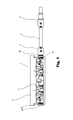
- Fig. 1 is a partial section view of a BIPV junction box, being connected with an external cable, according to a first embodiment of the present invention
- Fig. 2 is a perspective view of a housing of the junction box according to the first embodiment of the present invention
- Figs. 3A and 3B are a perspective view and a front view of a connection assembly according to the first embodiment of the present invention, respectively;
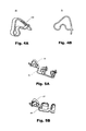
- Figs. 4A and 4B are a perspective view and a front view of a spring clamp according to the present invention, respectively;
- Figs. 5A and 5B are perspective views showing assemblies consisting of spring clamps and conductive rails according to the first embodiment and a second embodiment of the present invention, respectively;
- Fig. 6 is a side view schematically showing the junction box according to the first embodiment of the present invention in a state of being mounted on a BIPV glass panel;
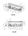
- Figs. 7A and 7B are partially sectioned perspective and front views, respectively, showing the structure of a junction box according to the second embodiment of the present invention.
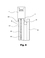
- Fig. 8 is a side view showing the junction box according to the second embodiment in a state of being mounted on an edge of a solar cell panel, in which hooks at ends of jaws of the junction box are engaged with a plastic rim extending and disposed along the edge of the solar cell panel;
- Figs. 9A and 9B are partially sectioned perspective and front views, respectively, showing the structure of a junction box according to a third embodiment of the present invention.
- Fig. 1 is a partial section view showing a BIPV junction box 1 according to the first embodiment of the present invention, in which some of sidewalls of a housing 4 of the junction box 1 is removed to show the inner structure of the junction box 1.
- the junction box 1 shown in Fig. 1 has one end connected with an external cable 3 and the other end sealed by a blocking bolt 6b.
- the junction box 1 may include the housing 4 and a connection assembly 5 disposed within the housing 4.
- the connection assembly 5 may be used to connect leads of solar cell modules, external cables and bypass diodes, etc.
- the housing 4 in the first embodiment of the present invention may have a shape of rectangular parallelepiped box in general, which has a closed bottom and an opened top.
- Through holes 41h are formed in sidewalls 41 at both ends of the housing 4, so that the external cable 3 may be connected to the connection assembly 5 through one of the through holes 41h.
- Sidewalls 42 of the housing 4 extending in a lengthwise direction of the housing 4 have extension parts higher than the sidewalls 41, and the distance between the opposite extension parts may be consistent with the thickness of an edge portion of a solar cell panel for installing the junction box thereon so that the edge portion of the solar cell panel may be sandwiched between the opposite extension parts when the junction box 1 is mounted.
- each of the sidewalls 41 may have a folded part at the top side thereof far away from a bottom wall 43, which may extend outwards in the lengthwise direction of the housing 4.
- the extension parts of the sidewalls 42 preferably extend in the lengthwise direction of the housing to outer edges of the folded parts of the sidewalls 41.
- the folded parts of the sidewalls 41 may increase contact area between the junction box 1 and the edge of the solar cell panel, and thus enhance the mounting stability and the sealing effect.
- the folded parts at the top sides of the sidewalls 41 are not indispensable, and the designs of the extension parts of the sidewalls 42 may be varied, for example the edges of the extension parts may be curved, as long as the inner space of the housing can be closed when the housing 4 is mounted to the edge portion of the solar cell panel.
- the two sidewalls 42 of the housing 4 may be parallel to each other corresponding to the parallel configuration of opposite surfaces of the solar cell panel.
- the shape of the housing 4 may be varied in accordance with the shape of the solar cell panel so long as the configuration of the sidewalls of the housing 4 allows the hermetic attachment of the housing to the surfaces of the solar cell panel.
- the housing 4 may be made of insulating material.
- connection assembly 5 in the housing 4 comprises a chassis 51 and two assemblies consisting of conductive rails 52 and spring clamps 53 installed in the chassis 51.
- the chassis 51 has a sidewall 511 extending in a lengthwise direction of the chassis, and is opened at the opposite side to the sidewall 511 so as to facilitate the installation of the conductive rails, the spring clamps and the like in the chassis.
- Sidewalls 512 at both ends of the chassis 51 may have screw holes 512h therethrough (the threads of which are not shown in Figs. 3A and 3B ), which may also serve as passages for components i.e., passages for inserting the external cables 3 into the housing.
- Ribs 513a, 513b and 513c extending from a bottom wall 513 toward a top wall 514 may be provided symmetrically on two sides of the chassis 51, wherein the ribs 513a and 513b may function to limit the positions of the conductive rails 52, and the rib 513c may be used to limit the drooping of overhang portions of the conductive rails 52 due to external force.
- the top wall 514 of the chassis 51 has a component passage 514a formed in the center thereof, and component passages 514b and actuator passages 514c, 514d and 514e symmetrically disposed at two sides of the component passage 514a with respect to the component passage 514a.
- the actuator passages allow the insertion of a tool for pressing the spring clamps, so that the spring clamps can be opened.
- Each of the spring clamps 53 has a mouth 533 facing a corresponding passage.
- the actuator passages 514c and 514d preferably have inclined guiding ribs 514cr and 514dr extending from the top wall at respective openings thereof toward the bottom wall 513 and the corresponding spring clamps 53.
- a bypass diode D is installed into the chassis 51 through the component passage 514a.
- a supporter 515 on the bottom wall 513 corresponding to the component passage 514a, so that the lowest position of the diode D in the chassis can be limited when it is inserted into the chassis 51.
- the leads of the solar cell panel are inserted into the chassis 51 through the component passages 514b.
- isolation ribs 516 may be formed on the top wall 514 at edges of openings of the component passages 514b, which extend outwards and may assist to prevent the leads of the solar cell panel from contacting each other and shorting.
- Figs. 4A and 4B there is shown the structure of the spring clamp 53.
- the spring clamps 53 of the present invention may have different dimensions from each other according to practice.
- the spring clamps 53 are opened and then clamp corresponding spring-mounting parts of the conductive rails 52, as shown in Fig. 5A ; after assembling the spring clamps and the conductive rails together, the assemblies of the spring clamps and the conductive rails are installed in the chassis 51, such that posts 511p formed on the sidewall 511 of the chassis 51 are inserted into tails of the spring clamps to assist the restriction of the positions of the spring clamps, as shown in Figs. 3A and 3B .
- the two assemblies of the conductive rails and spring clamps shown in the drawings may have the same structure, and one of the two assemblies of the conductive rails and spring clamps is rotated by 180° with respect to the other in installation. That is, the two assemblies are rotationally symmetrical with respect to a central axis of the chassis 51 which is perpendicular to the bottom wall of the chassis.
- the chassis 51 may be made of heat resistance insulating material such as PEI; and the conductive rail 52 and the spring clamp 53 may be made of conductive material such as metal.
- a double-ended screw joint 6a is fitted in the screw hole 512h of the chassis 51 of the connection assembly 5 through the through-hole 41h of the housing 4.
- an O-ring 61 is placed between a flange in the middle of the double-ended screw joint 6a and the sidewall 41 of the housing 4 to prevent dusts and moisture from entering into the inner space of the junction box through the through-hole 41h.
- the blocking bolt 6b may be fixed in a way same as the double-ended screw joint 6a.
- the junction box 1 may also be connected with external cables 3 at both ends thereof according to practice. In this case, the blocking bolt 6b is replaced by a double-ended screw joint 6a.
- the tool for pressing the spring clamps is inserted via the passage 514c, 514d or 514e to press and open one of the spring clamps 53; and at the same time, the bypass diode D, a lead of the solar cell module or a cable is inserted via the passage 514a, the passage 514b, or the screw hole 512h, so that one of the terminals of the diode D or other lead is disposed in the mouth 533 (see Fig. 3A ) of the spring clamp between a corresponding spring-mounting part of the conductive rail 52 and an edge of the mouth 533.
- the diode D may be mounted after assembling the connection assembly 5, or after installing the connection assembly 5 into the housing 4 and fitting the double-ended screw joint 6a and the blocking bolt 6b into the screw holes 512h of the chassis 51, or mounted at the construction site;
- the cable 3 may be installed after installing the connection assembly 5 into the housing 4 and fitting the double-ended screw joint 6a and the blocking bolt 6b into the screw holes 512h of the chassis 51, or installed at the construction site;
- the leads of the solar cell module may be mounted at the construction site.
- the cable 3 may has a distal end provided with a male or female connector 2 so that it can be connected to another cable.
- both ends of the junction box 1 may be closed by the blocking bolts 6b.
- the sidewall(s) 41 may have no through-hole 41h (see Fig. 2 ) at one or two ends of the housing not connected with the cable 3.
- the spring clamp adjacent to the sidewall 512 of the chassis 51 for connecting the cable 3 may be eliminated if the cable 3 is not connected to the junction box at the sidewall 512.
- the BIPV glass panel shown in Fig. 6 is a typical BIPV glass panel, which comprises a solar cell panel 81 and a glass plate 82 with an interval therebetween maintained by spacers 83.
- the solar cell panel 81 includes two glass plates 811 and 812 and a solar cell module 813 sandwiched between the glass plates 811 and 812.
- Fig. 6 shows that an edge portion of the solar cell panel is inserted and clamped between the two extension parts of the sidewalls 42 of the housing 4 of the junction box.
- the junction box according to the first embodiment of the present invention may be mounted at the construction site.
- the leads (not shown) of the solar cell module 813 are connected to the connection assembly 5, and then an adhesive such as silica gel is coated on surfaces of the sidewalls of the housing 4 of the junction box 1 that will contact the edge portion of the solar cell panel 81.
- the junction box 1 is placed on the edge of the solar cell panel 81 in such a manner that the opening of the housing 4 faces the solar cell panel 81, so that the edge portion is inserted between the two sidewalls 42 of the housing 4 in the lengthwise direction and a side surface of the solar cell panel 81 is in contact with the top of the sidewalls 41 of the housing 4, and thus the junction box 1 is adhered on the solar cell panel 81.
- the junction box 1 is hermetically mounted on the edge of the solar cell panel 81 with the adhesive of silica gel.
- the BIPV junction box according to the present invention is not filled with sealant as done in the prior art, and thus it is easy and convenient for those skilled in the art to repair or replace fault components.
- the BIPV junction box according to the present invention is mounted on the edge portion of the solar cell panel and has substantially the same thickness as that of the solar cell panel due to the design of the housing. As a result, the junction box can be hidden in the window frame easily, which achieves the object of providing good looks while effectively preventing the components therein from being damaged due to external impacts, dusts, and/or moisture.
- connection assembly of the BIPV junction box comprises spring clamps, the connection of leads or conductive wires is easy, quick, and fast, and the excellent electrical connection may be ensured.
- a screw joint matching the screw joint 7 of the cable may be integrally formed on the sidewall 41 of the housing 4.
- latch pairs may be formed on the chassis 51 and the sidewalls of the housing 4, so that the connection assembly 5 may be securely installed within the housing 4 via the latch pairs.
- those skilled in the art may modify the connection assembly 5 illustrated in the embodiments so long as it can connect leads or conductive wires reliably.
- Figs. 7A and 7B are partially sectioned perspective and front views, respectively, showing the structure of a junction box according to the second embodiment of the present invention, in which some sidewalls of a main body 40' of a housing of junction box 1' are removed to exhibit the inner structure of the junction box 1'.
- the BIPV junction box 1' according to the second embodiment of the present invention comprises an insulating housing and a connection assembly disposed in the housing.
- the housing includes the main body 40' and a closing cover 20', which are in a state of to be assembled and are separated from each other in Figs. 7A and 7B .
- the main body 40' has substantially a rectangular parallelepiped shape, and comprises two sidewalls 42' extending in a lengthwise direction, sidewalls 41' being connected with the two sidewalls 42' at ends of the sidewalls 42', and a bottom wall 43'.
- a plurality pairs of jaws 45' are disposed on the bottom of the main body 40' and extend downwards from the bottom wall 43' along a plane where the sidewall 42' lies, so that the main body 40' will be mounted on an edge of the solar cell panel 81 in such a manner that the bottom wall 43' faces the solar cell panel 81, which is contrary to the first embodiment.
- There may be one or more pairs of jaws 45' so long as they can clamp the edge of the solar cell panel.
- the main body 40' shown in Figs. 7A and 7B has three pairs of jaws 45'.
- Each of the jaws 45' may be provided with a hook 451' on the inward surface thereof at a distal end, which may be engaged with the plastic rim 9 extending and disposed along the edge of the solar cell panel 81 and having a "U" shaped cross section, as shown in Fig. 8 .
- the plastic rim 9 is formed with holes (not shown) which allow the leads of the solar cell module to pass through.
- the hook 451' and the plastic rim 9 may be omitted, and in this case, the jaws 45' clamp the edge of the solar cell panel 81 and optionally are adhered thereto with adhesive.
- the bottom wall 43' may have two lead holes 43h', which allow the leads of the solar cell module to pass through and enter into the main body 40'.
- the sidewalls 41' and 42' are level with each other at the top opening of the main body 40', which is different from the first embodiment.
- the ribs 513'a, 513'd, and 513'e are not indispensable and may be omitted entirely or partially, as long as the stiffness of the main body 40' meets the requirement for use and the position of the connection assembly may be kept constantly.
- the closing cover 20' covers and closes the top opening of the main body 40' by the engagement of latch catches 21' at ends of the closing cover with protrusions 411' formed on outer surfaces of the sidewalls 41'.
- An O-ring 22' is disposed around a raised portion of the closing cover 20', which is formed on a side of the closing cover 20' facing the top opening of the main body 40', so that the sealing between the closing cover 20' and the main body 40' is achieved when the cover 20' is mounted on the main body 40'.
- the sidewalls 41' of the main body 40' may have no through hole therein, as shown in Figs. 7A and 7B .
- the junction box 1' can connect only the leads of the solar cell module among the external components.
- spring clamps 53'-c among the spring clamps 53' closer to the sidewalls 41' for connecting external cables may be omitted.
- connection assembly disposed in the main body 40' comprises two assemblies of conductive rails 52' and the spring lamps 53', but does not comprise the chassis 51 of the first embodiment.
- the two assemblies of the conductive rails 52' and the spring lamps 53' may be same as each other, and one of the assemblies is rotated by 180° with respect to the other about a central axis of the junction box 1' such that the two assemblies are rotationally symmetrical with respect to each other, in which the central axis is perpendicular to the bottom wall 43' of the main body 40'.
- the assemblies of conductive rails and spring lamps in the second embodiment of the invention are substantially the same as those in the first embodiment except that the spring clamp 53'-b for clamping a lead of the solar cell module and the spring clamp 53'-a for clamping a lead of the bypass diode D among the spring clamps 53' are rotated by 90° with respect to those in the first embodiment to have the backs thereof face one of the sidewalls 42' of the main body 40'. Also, branches (spring-mounting parts) of the conductive rail 52' for mounting the spring clamps are rotated accordingly.
- a mouth of the spring clamp 53'-b for clamping a lead of the solar cell module may correspond to a lead hole 43h' in the bottom wall 43' of the main body 40'.
- the conductive rails 52' may be fixed within the main body 40' by adhering, clamping, or the like.
- the junction box 1' of the second embodiment of the present invention may further comprise an O-ring 431' disposed on an outer surface of the bottom wall 43' and enclosing the lead holes 43h' in the bottom wall 43'.
- the O-ring 431' When the junction box 1' is mounted on the edge of the solar cell panel, the O-ring 431' is positioned between the bottom wall 43' and a surface of the solar cell panel at the edge facing the bottom wall 43', so that the sealing between the bottom wall 43' and the surface of the solar cell panel is achieved.
- the junction box 1' may have no O-ring 431' and the sealing function of the O-ring 431' can be achieved by use of a sealing adhesive.
- Figs. 9A and 9B are partially sectioned perspective and front views, respectively, showing the third embodiment of the present invention. Similar to Figs. 7A and 7B , some sidewalls of the main body 40' of the housing of the junction box are removed in Figs. 9A and 9B to exhibit the inner structure of the junction box. The junction box of the present embodiment may be connected to an external cable at one end thereof.
- the third embodiment shown in Figs. 9A and 9B is substantially the same as the second embodiment shown in Figs. 7A and 7B except that there is a cylinder-shaped cable socket 46' integrally formed with the main body 40' on an outer surface of the sidewall 41', wherein the sidewall 41' is at one end of the main body 40'.
- the cable socket 46' has therein a pin P that extends in an axial direction of the cable socket to penetrate the sidewall 41' hermetically and is connected to the connection assembly.
- the cable socket 46' is used to match with a plug of an external cable.
- the cable socket 46' may be fabricated separately, and then adhere to the sidewall 41'. It is certain that the cable socked 46' may be fixed to the sidewall 41' by means of other ways.
- another cylinder-shaped cable socket 46' may be formed similarly on the other sidewall 41' of the junction box shown in Figs. 9A and 9B .
- the pin P in the cable socket 46' may penetrate the sidewall 41', and be inserted in the mouth of the spring clamp 53'-c among the spring clamps 53' located at the end of the main body 40' to be clamped by the spring clamp 53'-c.
- junction box according to the third embodiment may be similar to that according to the second embodiment of the present invention, and the repetitive description is omitted.
Abstract
Description
- The present invention relates to a building integrated photovoltaic (BIPV) device, and more particularly, to a junction box for BIPV glass panel.
- Solar energy is recyclable energy. The technology of converting the solar energy to electrical energy has attracted much attention of the public in recent years since it can save energy, lessen the short of power supply, and reduce environment pollution.
- A typical way of utilizing the solar energy is that a solar cell assembly (or photovoltaic assembly) is mounted via supports on a roof that has been built, and junction boxes used for the solar cell assembly are generally provided on the back surface of the assembly.
- Recently, a novel technology of utilizing the solar energy, i.e., building integrated photovoltaic (BIPV) technology, has been developed. The technology uses solar energy (photovoltaic) devices as parts of a building, such as transparent roofs, windows or glass walls. Such photovoltaic devices can keep out wind and rain and transmit sunlight while generating electricity. However, the conventional junction boxes for solar cell modules are unharmonious and inaesthetic when they are mounted on windows or the like, since they have large volumes.
- One solution in the prior arts is to hide connecting assembles in window frames or the like without using the junction box. However, without protection of the junction boxes, the connecting assembles are susceptible to external impacts, humidity and dusts.
- One object of the invention is to provide a junction box for a BIPV device, which can protect a diode assembly well without deteriorating appearance of a building having the BIPV device.
- According to the present invention, a building integrated photovoltaic (BIPV) junction box is provided, which comprises a housing and a connection assembly disposed within the housing, wherein the housing includes two first sidewalls opposite to each other, second sidewalls connecting said two first sidewalls, and an opening side and a bottom wall connecting said first and second sidewalls, and wherein the first sidewalls have extension parts higher than the second sidewalls, so that an edge of a solar cell panel is sandwiched between the extension parts when the junction box is mounted on the edge of the solar cell panel.
- In a preferred embodiment of the present invention, the extension parts of the first sidewalls are located at the opening side, the bottom wall is opposite to the opening side, and there is at least one opening at the opening side.
- In a preferred embodiment of the present invention, the opening side is apart from the extension parts of the first sidewalls, the bottom wall is opposite to the opening side, and the opening side is closed by a closing cover.
- In a preferred embodiment of the present invention, the extension parts comprise at least a pair of jaws.
- In a preferred embodiment of the present invention, each of the jaws has a hook formed on an inner surface at a distal end thereof.
- In a preferred embodiment of the present invention, at least one of the second sidewalls has a through hole therein, which allows an external cable to penetrate the housing and be connected to the connection assembly in the housing.
- In a preferred embodiment of the present invention, the bottom wall has through holes allowing leads of the solar cell panel to pass through.
- In a preferred embodiment of the present invention, the junction box further comprises a cylinder-shaped cable socket formed on an outer surface of at least one of the second sidewalls, wherein the cylinder-shaped cable socket has therein a pin that extends in an axial direction of the cable socket and penetrates the at least one of the second sidewalls hermetically to be connected to the connection assembly.
- In a preferred embodiment of the present invention, the connection assembly comprises conductive rails and spring clamps for electrically connecting and fixing external cables and leads of the solar cell panel, respectively.
- In a preferred embodiment of the present invention, the connection assembly further comprises an insulating chassis for holding the conductive rails and the spring clamps.
- In a preferred embodiment of the present invention, the connection assembly further comprises a bypass diode for overcurrent protection, which is connected in series or in parallel with the solar cell panel via leads of the solar cell panel.
- In a preferred embodiment of the present invention, components of the connection assembly are arranged in a line for saving room.
- In a preferred embodiment of the present invention, at least one of the spring clamps has a back thereof face one of the first sidewalls of the housing.
- In a preferred embodiment of the present invention, the connection assembly comprises two sub-assemblies each comprising one conductive rail and a plurality of spring clamps, the two sub-assemblies are the same as each other and are rotationally symmetrical with respect to a central axis of the housing perpendicular to the bottom wall of the housing.
- The BIPV junction box according to the invention is compact and thin, so that it can be hidden in a window frame completely while providing sufficient protections for components such as bypass diode. Further, the BIPV junction box according to the invention is easy to be replaced and repaired.
-
Fig. 1 is a partial section view of a BIPV junction box, being connected with an external cable, according to a first embodiment of the present invention; -
Fig. 2 is a perspective view of a housing of the junction box according to the first embodiment of the present invention; -
Figs. 3A and 3B are a perspective view and a front view of a connection assembly according to the first embodiment of the present invention, respectively; -
Figs. 4A and 4B are a perspective view and a front view of a spring clamp according to the present invention, respectively; -
Figs. 5A and 5B are perspective views showing assemblies consisting of spring clamps and conductive rails according to the first embodiment and a second embodiment of the present invention, respectively; -
Fig. 6 is a side view schematically showing the junction box according to the first embodiment of the present invention in a state of being mounted on a BIPV glass panel; -
Figs. 7A and 7B are partially sectioned perspective and front views, respectively, showing the structure of a junction box according to the second embodiment of the present invention; -
Fig. 8 is a side view showing the junction box according to the second embodiment in a state of being mounted on an edge of a solar cell panel, in which hooks at ends of jaws of the junction box are engaged with a plastic rim extending and disposed along the edge of the solar cell panel; and -
Figs. 9A and 9B are partially sectioned perspective and front views, respectively, showing the structure of a junction box according to a third embodiment of the present invention. -
Fig. 1 is a partial section view showing aBIPV junction box 1 according to the first embodiment of the present invention, in which some of sidewalls of ahousing 4 of thejunction box 1 is removed to show the inner structure of thejunction box 1. Thejunction box 1 shown inFig. 1 has one end connected with anexternal cable 3 and the other end sealed by a blocking bolt 6b. Thejunction box 1 may include thehousing 4 and aconnection assembly 5 disposed within thehousing 4. Theconnection assembly 5 may be used to connect leads of solar cell modules, external cables and bypass diodes, etc. - With reference to
Fig. 2 , thehousing 4 in the first embodiment of the present invention may have a shape of rectangular parallelepiped box in general, which has a closed bottom and an opened top. Throughholes 41h are formed insidewalls 41 at both ends of thehousing 4, so that theexternal cable 3 may be connected to theconnection assembly 5 through one of the throughholes 41h.Sidewalls 42 of thehousing 4 extending in a lengthwise direction of thehousing 4 have extension parts higher than thesidewalls 41, and the distance between the opposite extension parts may be consistent with the thickness of an edge portion of a solar cell panel for installing the junction box thereon so that the edge portion of the solar cell panel may be sandwiched between the opposite extension parts when thejunction box 1 is mounted. Optionally, each of thesidewalls 41 may have a folded part at the top side thereof far away from abottom wall 43, which may extend outwards in the lengthwise direction of thehousing 4. In this case, the extension parts of thesidewalls 42 preferably extend in the lengthwise direction of the housing to outer edges of the folded parts of thesidewalls 41. The folded parts of thesidewalls 41 may increase contact area between thejunction box 1 and the edge of the solar cell panel, and thus enhance the mounting stability and the sealing effect. However, the folded parts at the top sides of thesidewalls 41 are not indispensable, and the designs of the extension parts of thesidewalls 42 may be varied, for example the edges of the extension parts may be curved, as long as the inner space of the housing can be closed when thehousing 4 is mounted to the edge portion of the solar cell panel. In a preferred embodiment of the present invention, the twosidewalls 42 of thehousing 4 may be parallel to each other corresponding to the parallel configuration of opposite surfaces of the solar cell panel. However, the shape of thehousing 4 may be varied in accordance with the shape of the solar cell panel so long as the configuration of the sidewalls of thehousing 4 allows the hermetic attachment of the housing to the surfaces of the solar cell panel. Thehousing 4 may be made of insulating material. - Referring to
Figs. 3A and 3B , theconnection assembly 5 in thehousing 4 comprises achassis 51 and two assemblies consisting ofconductive rails 52 andspring clamps 53 installed in thechassis 51. - The
chassis 51 has asidewall 511 extending in a lengthwise direction of the chassis, and is opened at the opposite side to thesidewall 511 so as to facilitate the installation of the conductive rails, the spring clamps and the like in the chassis.Sidewalls 512 at both ends of thechassis 51 may havescrew holes 512h therethrough (the threads of which are not shown inFigs. 3A and 3B ), which may also serve as passages for components i.e., passages for inserting theexternal cables 3 into the housing.Ribs bottom wall 513 toward atop wall 514 may be provided symmetrically on two sides of thechassis 51, wherein theribs conductive rails 52, and therib 513c may be used to limit the drooping of overhang portions of theconductive rails 52 due to external force. Thetop wall 514 of thechassis 51 has acomponent passage 514a formed in the center thereof, andcomponent passages 514b andactuator passages component passage 514a with respect to thecomponent passage 514a. The actuator passages allow the insertion of a tool for pressing the spring clamps, so that the spring clamps can be opened. Each of the spring clamps 53 has amouth 533 facing a corresponding passage. In order to assist the tool for pressing the spring clamps to press the spring clamps, theactuator passages bottom wall 513 and the corresponding spring clamps 53. - In the first embodiment of the present invention, a bypass diode D is installed into the
chassis 51 through thecomponent passage 514a. In this case, it is preferred that there is asupporter 515 on thebottom wall 513 corresponding to thecomponent passage 514a, so that the lowest position of the diode D in the chassis can be limited when it is inserted into thechassis 51. - In a preferred embodiment of the present invention, the leads of the solar cell panel are inserted into the
chassis 51 through thecomponent passages 514b. Optionally,isolation ribs 516 may be formed on thetop wall 514 at edges of openings of thecomponent passages 514b, which extend outwards and may assist to prevent the leads of the solar cell panel from contacting each other and shorting. - Referring to
Figs. 4A and 4B , there is shown the structure of thespring clamp 53. The spring clamps 53 of the present invention may have different dimensions from each other according to practice. When assembling theconnection assembly 5, the spring clamps 53 are opened and then clamp corresponding spring-mounting parts of theconductive rails 52, as shown inFig. 5A ; after assembling the spring clamps and the conductive rails together, the assemblies of the spring clamps and the conductive rails are installed in thechassis 51, such that posts 511p formed on thesidewall 511 of thechassis 51 are inserted into tails of the spring clamps to assist the restriction of the positions of the spring clamps, as shown inFigs. 3A and 3B . - The two assemblies of the conductive rails and spring clamps shown in the drawings may have the same structure, and one of the two assemblies of the conductive rails and spring clamps is rotated by 180° with respect to the other in installation. That is, the two assemblies are rotationally symmetrical with respect to a central axis of the
chassis 51 which is perpendicular to the bottom wall of the chassis. - In a preferred embodiment of the present invention, the
chassis 51 may be made of heat resistance insulating material such as PEI; and theconductive rail 52 and thespring clamp 53 may be made of conductive material such as metal. - Referring to
Fig. 1 again, after theconnection assembly 5 is mounted within thehousing 4, one end of a double-ended screw joint 6a is fitted in thescrew hole 512h of thechassis 51 of theconnection assembly 5 through the through-hole 41h of thehousing 4. Preferably, an O-ring 61 is placed between a flange in the middle of the double-ended screw joint 6a and thesidewall 41 of thehousing 4 to prevent dusts and moisture from entering into the inner space of the junction box through the through-hole 41h. The blocking bolt 6b may be fixed in a way same as the double-ended screw joint 6a. Alternatively, thejunction box 1 may also be connected withexternal cables 3 at both ends thereof according to practice. In this case, the blocking bolt 6b is replaced by a double-ended screw joint 6a. - Next, the use of the junction box will be described. Briefly, the tool for pressing the spring clamps is inserted via the
passage passage 514a, thepassage 514b, or thescrew hole 512h, so that one of the terminals of the diode D or other lead is disposed in the mouth 533 (seeFig. 3A ) of the spring clamp between a corresponding spring-mounting part of theconductive rail 52 and an edge of themouth 533. Then, the tool is withdrawn, and thespring clamp 53 is restored to securely fix the terminal of the diode D or the other lead on theconductive rail 52 and achieve excellent electrical connection. Although the connecting of the bypass diode D, the lead of the solar cell module or the cable and the junction box is described as above, this description is only for the purpose of facilitating the understanding of the invention, and those skilled in the art can determine flexibly according to particular conditions the time to connect respective components or leads. For example, the diode D may be mounted after assembling theconnection assembly 5, or after installing theconnection assembly 5 into thehousing 4 and fitting the double-ended screw joint 6a and the blocking bolt 6b into the screw holes 512h of thechassis 51, or mounted at the construction site; thecable 3 may be installed after installing theconnection assembly 5 into thehousing 4 and fitting the double-ended screw joint 6a and the blocking bolt 6b into the screw holes 512h of thechassis 51, or installed at the construction site; and the leads of the solar cell module may be mounted at the construction site. - Referring to
Fig. 1 again, one end of the double-ended screw joint 6a exposed outside thehousing 4 serves to mount ascrew joint 7 of the cable. Thecable 3 may has a distal end provided with a male orfemale connector 2 so that it can be connected to another cable. - Further, in the case that no external cable is necessary, both ends of the
junction box 1 may be closed by the blocking bolts 6b. Alternatively, the sidewall(s) 41 may have no through-hole 41h (seeFig. 2 ) at one or two ends of the housing not connected with thecable 3. Also, the spring clamp adjacent to thesidewall 512 of thechassis 51 for connecting thecable 3 may be eliminated if thecable 3 is not connected to the junction box at thesidewall 512. - Next, the installation of the
BIPV junction box 1 according to the first embodiment of the present invention will be described with reference to the schematic view ofFig. 6 . The BIPV glass panel shown inFig. 6 is a typical BIPV glass panel, which comprises asolar cell panel 81 and aglass plate 82 with an interval therebetween maintained byspacers 83. Thesolar cell panel 81 includes twoglass plates solar cell module 813 sandwiched between theglass plates Fig. 6 shows that an edge portion of the solar cell panel is inserted and clamped between the two extension parts of thesidewalls 42 of thehousing 4 of the junction box. Upon it is assembled, the junction box according to the first embodiment of the present invention may be mounted at the construction site. At the construction site, the leads (not shown) of thesolar cell module 813 are connected to theconnection assembly 5, and then an adhesive such as silica gel is coated on surfaces of the sidewalls of thehousing 4 of thejunction box 1 that will contact the edge portion of thesolar cell panel 81. Next, thejunction box 1 is placed on the edge of thesolar cell panel 81 in such a manner that the opening of thehousing 4 faces thesolar cell panel 81, so that the edge portion is inserted between the twosidewalls 42 of thehousing 4 in the lengthwise direction and a side surface of thesolar cell panel 81 is in contact with the top of thesidewalls 41 of thehousing 4, and thus thejunction box 1 is adhered on thesolar cell panel 81. As a result, thejunction box 1 is hermetically mounted on the edge of thesolar cell panel 81 with the adhesive of silica gel. - The BIPV junction box according to the present invention is not filled with sealant as done in the prior art, and thus it is easy and convenient for those skilled in the art to repair or replace fault components.
- The BIPV junction box according to the present invention is mounted on the edge portion of the solar cell panel and has substantially the same thickness as that of the solar cell panel due to the design of the housing. As a result, the junction box can be hidden in the window frame easily, which achieves the object of providing good looks while effectively preventing the components therein from being damaged due to external impacts, dusts, and/or moisture.
- Since the connection assembly of the BIPV junction box according to the present invention comprises spring clamps, the connection of leads or conductive wires is easy, quick, and fast, and the excellent electrical connection may be ensured.
- The above embodiments are not to limit the scopes of the present invention, and those skilled in the art may make various changes of them. For example, instead of the separate double-ended screw joint 6a, a screw joint matching the
screw joint 7 of the cable may be integrally formed on thesidewall 41 of thehousing 4. In this case, although the manufacture of thehousing 4 is complicated, the hermetical connection between the cable and the junction box becomes simpler and more reliable. Further, latch pairs may be formed on thechassis 51 and the sidewalls of thehousing 4, so that theconnection assembly 5 may be securely installed within thehousing 4 via the latch pairs. In addition, those skilled in the art may modify theconnection assembly 5 illustrated in the embodiments so long as it can connect leads or conductive wires reliably. - Hereinafter, a second embodiment of the present invention will be described with reference to
Figs. 7A, 7B , and8 , in which components like those in the first embodiment are denoted by like reference numerals and their repetitive descriptions are omitted. -
Figs. 7A and 7B are partially sectioned perspective and front views, respectively, showing the structure of a junction box according to the second embodiment of the present invention, in which some sidewalls of a main body 40' of a housing of junction box 1' are removed to exhibit the inner structure of the junction box 1'. - Referring to
Figs. 7A and 7B , the BIPV junction box 1' according to the second embodiment of the present invention comprises an insulating housing and a connection assembly disposed in the housing. - The housing includes the main body 40' and a closing cover 20', which are in a state of to be assembled and are separated from each other in
Figs. 7A and 7B . - The main body 40' has substantially a rectangular parallelepiped shape, and comprises two sidewalls 42' extending in a lengthwise direction, sidewalls 41' being connected with the two sidewalls 42' at ends of the sidewalls 42', and a bottom wall 43'. A plurality pairs of jaws 45' are disposed on the bottom of the main body 40' and extend downwards from the bottom wall 43' along a plane where the sidewall 42' lies, so that the main body 40' will be mounted on an edge of the
solar cell panel 81 in such a manner that the bottom wall 43' faces thesolar cell panel 81, which is contrary to the first embodiment. There may be one or more pairs of jaws 45' so long as they can clamp the edge of the solar cell panel. The main body 40' shown inFigs. 7A and 7B has three pairs of jaws 45'. Each of the jaws 45' may be provided with a hook 451' on the inward surface thereof at a distal end, which may be engaged with theplastic rim 9 extending and disposed along the edge of thesolar cell panel 81 and having a "U" shaped cross section, as shown inFig. 8 . In this case, theplastic rim 9 is formed with holes (not shown) which allow the leads of the solar cell module to pass through. Alternatively, the hook 451' and theplastic rim 9 may be omitted, and in this case, the jaws 45' clamp the edge of thesolar cell panel 81 and optionally are adhered thereto with adhesive. The bottom wall 43' may have twolead holes 43h', which allow the leads of the solar cell module to pass through and enter into the main body 40'. Thesidewalls 41' and 42' are level with each other at the top opening of the main body 40', which is different from the first embodiment. Optionally, there may be ribs 513'a, 513'd and 513'e formed on the bottom wall 43' and connected with the sidewalls 42' inside the main body 40', which serve to position the connection assembly and/or strengthen the main body 40'. However, the ribs 513'a, 513'd, and 513'e are not indispensable and may be omitted entirely or partially, as long as the stiffness of the main body 40' meets the requirement for use and the position of the connection assembly may be kept constantly. - The closing cover 20' covers and closes the top opening of the main body 40' by the engagement of latch catches 21' at ends of the closing cover with protrusions 411' formed on outer surfaces of the sidewalls 41'. An O-ring 22' is disposed around a raised portion of the closing cover 20', which is formed on a side of the closing cover 20' facing the top opening of the main body 40', so that the sealing between the closing cover 20' and the main body 40' is achieved when the cover 20' is mounted on the main body 40'.
- If no external cable is needed to be connected, the
sidewalls 41' of the main body 40' may have no through hole therein, as shown inFigs. 7A and 7B . In this case, the junction box 1' can connect only the leads of the solar cell module among the external components. Optionally, in the case where no external cable is needed to be connected, spring clamps 53'-c among the spring clamps 53' closer to thesidewalls 41' for connecting external cables may be omitted. - Referring to
Figs. 7A and 7B again, the connection assembly disposed in the main body 40' comprises two assemblies of conductive rails 52' and the spring lamps 53', but does not comprise thechassis 51 of the first embodiment. The two assemblies of the conductive rails 52' and the spring lamps 53' may be same as each other, and one of the assemblies is rotated by 180° with respect to the other about a central axis of the junction box 1' such that the two assemblies are rotationally symmetrical with respect to each other, in which the central axis is perpendicular to the bottom wall 43' of the main body 40'. As shown inFigs. 5B ,7A, and 7B , the assemblies of conductive rails and spring lamps in the second embodiment of the invention are substantially the same as those in the first embodiment except that the spring clamp 53'-b for clamping a lead of the solar cell module and the spring clamp 53'-a for clamping a lead of the bypass diode D among the spring clamps 53' are rotated by 90° with respect to those in the first embodiment to have the backs thereof face one of the sidewalls 42' of the main body 40'. Also, branches (spring-mounting parts) of the conductive rail 52' for mounting the spring clamps are rotated accordingly. In addition, a mouth of the spring clamp 53'-b for clamping a lead of the solar cell module may correspond to alead hole 43h' in the bottom wall 43' of the main body 40'. The conductive rails 52' may be fixed within the main body 40' by adhering, clamping, or the like. - The junction box 1' of the second embodiment of the present invention may further comprise an O-ring 431' disposed on an outer surface of the bottom wall 43' and enclosing the lead holes 43h' in the bottom wall 43'. When the junction box 1' is mounted on the edge of the solar cell panel, the O-ring 431' is positioned between the bottom wall 43' and a surface of the solar cell panel at the edge facing the bottom wall 43', so that the sealing between the bottom wall 43' and the surface of the solar cell panel is achieved. In an alternative embodiment, the junction box 1' may have no O-ring 431' and the sealing function of the O-ring 431' can be achieved by use of a sealing adhesive.
-
Figs. 9A and 9B are partially sectioned perspective and front views, respectively, showing the third embodiment of the present invention. Similar toFigs. 7A and 7B , some sidewalls of the main body 40' of the housing of the junction box are removed inFigs. 9A and 9B to exhibit the inner structure of the junction box. The junction box of the present embodiment may be connected to an external cable at one end thereof. The third embodiment shown inFigs. 9A and 9B is substantially the same as the second embodiment shown inFigs. 7A and 7B except that there is a cylinder-shaped cable socket 46' integrally formed with the main body 40' on an outer surface of thesidewall 41', wherein thesidewall 41' is at one end of the main body 40'. The cable socket 46' has therein a pin P that extends in an axial direction of the cable socket to penetrate thesidewall 41' hermetically and is connected to the connection assembly. The cable socket 46' is used to match with a plug of an external cable. Alternatively, the cable socket 46' may be fabricated separately, and then adhere to thesidewall 41'. It is certain that the cable socked 46' may be fixed to thesidewall 41' by means of other ways. In the case in which both ends of the junction box are connected with external cables, another cylinder-shaped cable socket 46' may be formed similarly on theother sidewall 41' of the junction box shown inFigs. 9A and 9B . The pin P in the cable socket 46' may penetrate thesidewall 41', and be inserted in the mouth of the spring clamp 53'-c among the spring clamps 53' located at the end of the main body 40' to be clamped by the spring clamp 53'-c. - The installation of the junction box according to the third embodiment may be similar to that according to the second embodiment of the present invention, and the repetitive description is omitted.
- Although the exemplary embodiments of the present invention have been shown and described above, it will be appreciated by those skilled in the art that changes may be made to the embodiments without departing from the principles and spirit of the invention, and the scope of the invention is defined in the claims and their equivalents.
Claims (14)
- A building integrated photovoltaic (BIPV) junction box, comprising:a housing and a connection assembly disposed within the housing, the housing including two first sidewalls opposite to each other, second sidewalls connecting said two first sidewalls, and an opening side and a bottom wall connecting said first and second sidewalls,wherein the first sidewalls have extension parts beyond the height of the second sidewalls, so that an edge of a solar cell panel is sandwiched between the extension parts when the junction box is mounted on the edge of the solar cell panel.
- The junction box as claimed in claim 1, wherein the extension parts of the first sidewalls beyond the second sidewalls are at the opening side, the bottom wall is opposite to the opening side, and there is at least one opening at the opening side.
- The junction box as claimed in claim 1, wherein the opening side is apart from the extension parts of the first sidewalls, the bottom wall is opposite to the opening side, and the opening side is closed by a closing cover.
- The junction box as claimed in any one of claims 1-3, wherein the extension parts comprise at least a pair of jaws.
- The junction box as claimed in claim 4, wherein each of the jaws has a hook formed on an inner surface at a distal end thereof.
- The junction box as claimed in any one of claims 1-3, wherein the second sidewall has a through hole therein, which allows an external cable to penetrate the housing and be connected to the connection assembly in the housing.
- The junction box as claimed in claim 3, wherein the bottom wall has through holes allowing leads of the solar cell panel to pass through.
- The junction box as claimed in any one of claims 1-3, further comprising a cylinder-shaped cable socket formed on an outer surface of at least one of the second sidewalls, wherein the cylinder-shaped cable socket has therein a pin that extends in an axial direction of the cable socket and penetrates the at least one of the second sidewalls hermetically to be connected to the connection assembly.
- The junction box as claimed in claim 1, wherein the connection assembly comprises conductive rails and spring clamps for electrically connecting and fixing external cables and leads of the solar cell panel, respectively.
- The junction box as claimed in claim 9, wherein the connection assembly further comprises an insulating chassis for holding the conductive rails and the spring clamps.
- The junction box as claimed in claim 1, wherein the connection assembly further comprises a bypass diode for overcurrent protection, which is connected in series or in parallel with the solar cell panel via leads of the solar cell panel.
- The junction box as claimed in any one of claims 9-11, wherein components of the connection assembly are arranged in a row for saving room.
- The junction box as claimed in claim 9, wherein at least one of the spring clamps has a back thereof face one of the first sidewalls of the housing.
- The junction box as claimed in claim 9, wherein the connection assembly comprises two sub-assemblies each comprising the conductive rail and the spring clamps, the two sub-assemblies are the same as each other and are rotationally symmetrical with respect to a central axis of the housing perpendicular to the bottom wall of the housing.
Applications Claiming Priority (1)
| Application Number | Priority Date | Filing Date | Title |
|---|---|---|---|
| CNU2008201259009U CN201260137Y (en) | 2008-07-18 | 2008-07-18 | Photovoltaic integrated wiring box for building |
Publications (2)
| Publication Number | Publication Date |
|---|---|
| EP2146383A2 true EP2146383A2 (en) | 2010-01-20 |
| EP2146383A3 EP2146383A3 (en) | 2013-08-21 |
Family
ID=40774374
Family Applications (1)
| Application Number | Title | Priority Date | Filing Date |
|---|---|---|---|
| EP09009176.0A Withdrawn EP2146383A3 (en) | 2008-07-18 | 2009-07-14 | Building integrated photovoltaic (BIPV) junction box |
Country Status (4)
| Country | Link |
|---|---|
| US (1) | US8203075B2 (en) |
| EP (1) | EP2146383A3 (en) |
| JP (1) | JP5424753B2 (en) |
| CN (1) | CN201260137Y (en) |
Cited By (9)
| Publication number | Priority date | Publication date | Assignee | Title |
|---|---|---|---|---|
| CN101944866A (en) * | 2010-09-15 | 2011-01-12 | 苏州快可光伏电子有限公司 | Glue-filling waterproof photovoltaic junction box |
| WO2011157340A1 (en) * | 2010-06-18 | 2011-12-22 | Phoenix Contact Gmbh & Co. Kg | Connecting device for photovoltaic modules and method for installing same |
| WO2013076285A1 (en) * | 2011-11-23 | 2013-05-30 | Phoenix Contact Gmbh & Co. Kg | Generator connection box for photovoltaic installations |
| WO2014009491A1 (en) * | 2012-07-11 | 2014-01-16 | Phoenix Contact Gmbh & Co. Kg | Edge connector for photovoltaic solar modules |
| WO2013038409A3 (en) * | 2011-09-12 | 2014-06-26 | Pythagoras Solar Inc. | Electrical joint |
| EP3035524A1 (en) * | 2014-12-17 | 2016-06-22 | Tyco Electronics (Shanghai) Co., Ltd. | Photovoltaic connection box and photovoltaic assembly |
| EP3598637A1 (en) | 2018-07-21 | 2020-01-22 | Lapp Engineering & Co. | Photovoltaic system, connection modules and connector |
| CN111487732A (en) * | 2020-04-15 | 2020-08-04 | 王加齐 | Multifunctional high-capacity optical fiber integrated tray |
| EP4350984A1 (en) | 2022-10-03 | 2024-04-10 | Lapp Engineering AG | Photovoltaic system, method for monitoring a photovoltaic system and plug connector |
Families Citing this family (25)
| Publication number | Priority date | Publication date | Assignee | Title |
|---|---|---|---|---|
| DE102008062034B4 (en) * | 2008-12-12 | 2010-08-12 | Tyco Electronics Amp Gmbh | Connecting device for connection to a solar module and solar module with such a connection device |
| US7824189B1 (en) * | 2009-04-15 | 2010-11-02 | Tyco Electronics Corporation | Junction box for photovoltaic modules |
| CN102195522B (en) * | 2010-03-15 | 2014-12-17 | 泰科电子(上海)有限公司 | Wiring module for BIPV (building integrated photovoltaic) system |
| US20110226305A1 (en) * | 2010-03-17 | 2011-09-22 | Industrial Technology Research Institute | Connection device for solar cell module |
| DE102010029714A1 (en) * | 2010-04-08 | 2011-10-13 | Tyco Electronics Amp Gmbh | Electrical spring clamp, punched grid, busbar and electrical connection device |
| CN102237414B (en) * | 2010-04-26 | 2014-07-30 | 杜邦公司 | Composite frame and manufacturing method thereof as well as solar cell module |
| DE212011100086U1 (en) * | 2010-04-26 | 2012-12-13 | E.I. Du Pont De Nemours And Co. | Distribution box, frame component and solar cell module |
| CN102237423B (en) * | 2010-04-26 | 2014-05-07 | 杜邦公司 | Junction box, frame component and solar cell module |
| CN102237413B (en) * | 2010-04-26 | 2014-07-09 | 杜邦公司 | Frame component of solar battery, solar battery module, solar battery system and installation method of solar battery system |
| CN102347577B (en) * | 2010-07-27 | 2013-07-17 | 泰科电子(上海)有限公司 | Electric connection system and frame with same |
| US8388358B2 (en) * | 2010-09-28 | 2013-03-05 | Tyco Electronics Corporation | Contact rail for a junction box |
| KR101020272B1 (en) * | 2010-10-12 | 2011-03-07 | 주식회사 넥센테크 | Apparatus for junction of building integrated photovoltaic module |
| CN102479857A (en) * | 2010-11-29 | 2012-05-30 | 比亚迪股份有限公司 | Solar cell module border and solar cell module |
| US9083121B2 (en) * | 2010-12-17 | 2015-07-14 | Sunpower Corporation | Diode-included connector, photovoltaic laminate and photovoltaic assembly using same |
| KR101200631B1 (en) | 2011-05-20 | 2012-11-12 | 코오롱글로벌 주식회사 | Building Integrated Photovoltaic System |
| JP5729648B2 (en) * | 2011-10-13 | 2015-06-03 | ホシデン株式会社 | Terminal box for solar cell module |
| CN102376806B (en) * | 2011-10-21 | 2012-11-21 | 常熟市冠日新材料有限公司 | Junction box capable of being arranged at side face of solar energy photovoltaic module |
| CN103367495B (en) * | 2012-04-09 | 2015-09-23 | 中电电气(上海)太阳能科技有限公司 | A kind of adhesive tape type terminal box pastes template |
| CN102912946B (en) * | 2012-09-07 | 2014-06-25 | 浙江合大太阳能科技有限公司 | Solar photovoltaic tile and manufacture method thereof |
| CN103812433B (en) * | 2012-11-15 | 2016-07-06 | 杜邦公司 | Photovoltaic module and integrated-type frame thereof |
| CN203456481U (en) * | 2013-07-16 | 2014-02-26 | 泰科电子(上海)有限公司 | Junction box |
| CN104426474B (en) * | 2013-08-21 | 2018-03-06 | 晶科能源有限公司 | A kind of solar cell module and its manufacture method |
| US11056997B2 (en) | 2015-06-27 | 2021-07-06 | Sunpower Corporation | Universal photovoltaic laminate |
| CN105702771B (en) * | 2016-04-11 | 2017-09-15 | 张家港协鑫集成科技有限公司 | The determination method of the power gear of photovoltaic structure and photovoltaic structure |
| CN106253839A (en) * | 2016-08-26 | 2016-12-21 | 张家港市互惠光电有限公司 | Solar assembly junction box |
Citations (4)
| Publication number | Priority date | Publication date | Assignee | Title |
|---|---|---|---|---|
| US6066796A (en) * | 1997-02-14 | 2000-05-23 | Canon Kabushiki Kaisha | Solar cell module |
| JP2003158285A (en) * | 2001-11-22 | 2003-05-30 | Sekisui Jushi Co Ltd | Method for manufacturing solar battery panel and terminal box for solar battery module |
| EP1912261A1 (en) * | 2006-10-13 | 2008-04-16 | Bertrand Courtaigne | Electrical connection device, in particular for an electric solar panel |
| US7387537B1 (en) * | 2007-01-03 | 2008-06-17 | Tyco Electronics Corporation | Connector system for solar cell roofing tiles |
Family Cites Families (3)
| Publication number | Priority date | Publication date | Assignee | Title |
|---|---|---|---|---|
| JP3769509B2 (en) * | 2002-01-31 | 2006-04-26 | 木谷電器株式会社 | Terminal box for solar cell module |
| US7337903B2 (en) * | 2003-01-07 | 2008-03-04 | Lauri Aaron P | Single edge razor blade holder |
| DE20311183U1 (en) * | 2003-07-21 | 2004-07-08 | Tyco Electronics Amp Gmbh | Junction box for a solar panel and solar panel |
-
2008
- 2008-07-18 CN CNU2008201259009U patent/CN201260137Y/en not_active Expired - Lifetime
-
2009
- 2009-07-10 JP JP2009163679A patent/JP5424753B2/en not_active Expired - Fee Related
- 2009-07-14 EP EP09009176.0A patent/EP2146383A3/en not_active Withdrawn
- 2009-07-15 US US12/503,545 patent/US8203075B2/en not_active Expired - Fee Related
Patent Citations (4)
| Publication number | Priority date | Publication date | Assignee | Title |
|---|---|---|---|---|
| US6066796A (en) * | 1997-02-14 | 2000-05-23 | Canon Kabushiki Kaisha | Solar cell module |
| JP2003158285A (en) * | 2001-11-22 | 2003-05-30 | Sekisui Jushi Co Ltd | Method for manufacturing solar battery panel and terminal box for solar battery module |
| EP1912261A1 (en) * | 2006-10-13 | 2008-04-16 | Bertrand Courtaigne | Electrical connection device, in particular for an electric solar panel |
| US7387537B1 (en) * | 2007-01-03 | 2008-06-17 | Tyco Electronics Corporation | Connector system for solar cell roofing tiles |
Cited By (14)
| Publication number | Priority date | Publication date | Assignee | Title |
|---|---|---|---|---|
| US8656661B2 (en) | 2010-06-18 | 2014-02-25 | Phoenix Contact Gmbh & Co. Kg | Connection device for photovoltaic modules and method for installing same |
| WO2011157340A1 (en) * | 2010-06-18 | 2011-12-22 | Phoenix Contact Gmbh & Co. Kg | Connecting device for photovoltaic modules and method for installing same |
| CN101944866B (en) * | 2010-09-15 | 2012-08-22 | 苏州快可光伏电子股份有限公司 | Glue-filling waterproof photovoltaic junction box |
| CN101944866A (en) * | 2010-09-15 | 2011-01-12 | 苏州快可光伏电子有限公司 | Glue-filling waterproof photovoltaic junction box |
| WO2013038409A3 (en) * | 2011-09-12 | 2014-06-26 | Pythagoras Solar Inc. | Electrical joint |
| WO2013076285A1 (en) * | 2011-11-23 | 2013-05-30 | Phoenix Contact Gmbh & Co. Kg | Generator connection box for photovoltaic installations |
| CN103999356A (en) * | 2011-11-23 | 2014-08-20 | 菲尼克斯电气公司 | Generator connection box for photovoltaic installations |
| US9466961B2 (en) | 2011-11-23 | 2016-10-11 | Phoenix Contact Gmbh & Co. Kg | Generator connection box for photovoltaic installations |
| CN103999356B (en) * | 2011-11-23 | 2017-04-26 | 菲尼克斯电气公司 | Generator connection box for photovoltaic installations |
| WO2014009491A1 (en) * | 2012-07-11 | 2014-01-16 | Phoenix Contact Gmbh & Co. Kg | Edge connector for photovoltaic solar modules |
| EP3035524A1 (en) * | 2014-12-17 | 2016-06-22 | Tyco Electronics (Shanghai) Co., Ltd. | Photovoltaic connection box and photovoltaic assembly |
| EP3598637A1 (en) | 2018-07-21 | 2020-01-22 | Lapp Engineering & Co. | Photovoltaic system, connection modules and connector |
| CN111487732A (en) * | 2020-04-15 | 2020-08-04 | 王加齐 | Multifunctional high-capacity optical fiber integrated tray |
| EP4350984A1 (en) | 2022-10-03 | 2024-04-10 | Lapp Engineering AG | Photovoltaic system, method for monitoring a photovoltaic system and plug connector |
Also Published As
| Publication number | Publication date |
|---|---|
| JP2010028114A (en) | 2010-02-04 |
| US8203075B2 (en) | 2012-06-19 |
| JP5424753B2 (en) | 2014-02-26 |
| EP2146383A3 (en) | 2013-08-21 |
| US20100012343A1 (en) | 2010-01-21 |
| CN201260137Y (en) | 2009-06-17 |
Similar Documents
| Publication | Publication Date | Title |
|---|---|---|
| EP2146383A2 (en) | Building integrated photovoltaic (BIPV) junction box | |
| US10622939B2 (en) | Bracket for connection of a junction box to photovoltaic panels | |
| US7694466B2 (en) | Solar cell unit attaching apparatus | |
| KR200448783Y1 (en) | a solar power generation | |
| KR100930103B1 (en) | Dividing apparatus junction box separation of solar photovoltaic power generation system | |
| US20100275976A1 (en) | Photovoltaic module with edge access to pv strings, interconnection method, apparatus, and system | |
| US20030098056A1 (en) | Window structure with photovoltaic panel | |
| US20160380588A1 (en) | Solar junction box | |
| CN109769410B (en) | Photovoltaic module with corner-facing electrical connector ports | |
| JP2007019140A (en) | Solar cell module, its connection method, installation structure, and installation method | |
| KR101016793B1 (en) | Roof unit including solar cell and roof connecting the same | |
| JP2003197944A (en) | Terminal box | |
| KR20190110709A (en) | Juction Box of Photovoltaic Module Used for Building Integrated Photovoltaic System | |
| JP5555085B2 (en) | Solar cell module | |
| JP2015005685A (en) | Photovoltaic power generation module | |
| KR20110009367U (en) | Efficient photovoltaic module junction box | |
| KR101155927B1 (en) | Junction box for building-integrated photovoltaic modules | |
| JP6594626B2 (en) | Roof structure | |
| CN220821585U (en) | Photovoltaic cell assembly | |
| CN212587878U (en) | Sealed protection against insects type electric cabinet body and electric cabinet | |
| US20210044096A1 (en) | Electrical module junction box transfer device (e-jbtd) system having electrical energy internal and external connections | |
| CN218482819U (en) | Photovoltaic square matrix, edge covering device thereof and photovoltaic system | |
| JP3359531B2 (en) | Solar cell module connection structure and solar cell module grounding method | |
| US11095248B2 (en) | Solar junction box | |
| CN114287106A (en) | Electrical modular junction box transmission device (E-JBTD) system with internal and external electrical power connections |
Legal Events
| Date | Code | Title | Description |
|---|---|---|---|
| PUAI | Public reference made under article 153(3) epc to a published international application that has entered the european phase |
Free format text: ORIGINAL CODE: 0009012 |
|
| AK | Designated contracting states |
Kind code of ref document: A2 Designated state(s): AT BE BG CH CY CZ DE DK EE ES FI FR GB GR HR HU IE IS IT LI LT LU LV MC MK MT NL NO PL PT RO SE SI SK SM TR |
|
| AX | Request for extension of the european patent |
Extension state: AL BA RS |
|
| PUAL | Search report despatched |
Free format text: ORIGINAL CODE: 0009013 |
|
| AK | Designated contracting states |
Kind code of ref document: A3 Designated state(s): AT BE BG CH CY CZ DE DK EE ES FI FR GB GR HR HU IE IS IT LI LT LU LV MC MK MT NL NO PL PT RO SE SI SK SM TR |
|
| AX | Request for extension of the european patent |
Extension state: AL BA RS |
|
| RIC1 | Information provided on ipc code assigned before grant |
Ipc: H01L 31/048 20060101AFI20130718BHEP Ipc: H02G 3/08 20060101ALI20130718BHEP |
|
| STAA | Information on the status of an ep patent application or granted ep patent |
Free format text: STATUS: THE APPLICATION IS DEEMED TO BE WITHDRAWN |
|
| 18D | Application deemed to be withdrawn |
Effective date: 20140222 |