US4636577A - Solar panel module and support therefor - Google Patents
Solar panel module and support therefor Download PDFInfo
- Publication number
- US4636577A US4636577A US06/527,439 US52743983A US4636577A US 4636577 A US4636577 A US 4636577A US 52743983 A US52743983 A US 52743983A US 4636577 A US4636577 A US 4636577A
- Authority
- US
- United States
- Prior art keywords
- solar panel
- frame
- walls
- solar
- interlocking
- Prior art date
- Legal status (The legal status is an assumption and is not a legal conclusion. Google has not performed a legal analysis and makes no representation as to the accuracy of the status listed.)
- Expired - Fee Related
Links
- 230000005855 radiation Effects 0.000 claims abstract description 11
- 239000000565 sealant Substances 0.000 claims description 8
- 230000002093 peripheral effect Effects 0.000 claims description 5
- 239000000853 adhesive Substances 0.000 claims description 4
- 230000001070 adhesive effect Effects 0.000 claims description 4
- 238000004891 communication Methods 0.000 claims description 3
- 239000000463 material Substances 0.000 claims 1
- 238000009434 installation Methods 0.000 abstract description 4
- 238000009877 rendering Methods 0.000 abstract 1
- 238000013461 design Methods 0.000 description 7
- 238000013459 approach Methods 0.000 description 4
- 238000010276 construction Methods 0.000 description 4
- 238000007789 sealing Methods 0.000 description 4
- 238000012423 maintenance Methods 0.000 description 3
- 239000000758 substrate Substances 0.000 description 3
- 238000009429 electrical wiring Methods 0.000 description 2
- 239000011521 glass Substances 0.000 description 2
- 230000010354 integration Effects 0.000 description 2
- 238000004519 manufacturing process Methods 0.000 description 2
- 238000000034 method Methods 0.000 description 2
- 238000004078 waterproofing Methods 0.000 description 2
- XUIMIQQOPSSXEZ-UHFFFAOYSA-N Silicon Chemical compound [Si] XUIMIQQOPSSXEZ-UHFFFAOYSA-N 0.000 description 1
- 238000009825 accumulation Methods 0.000 description 1
- 230000004888 barrier function Effects 0.000 description 1
- 125000000484 butyl group Chemical group [H]C([*])([H])C([H])([H])C([H])([H])C([H])([H])[H] 0.000 description 1
- 238000006243 chemical reaction Methods 0.000 description 1
- 230000000694 effects Effects 0.000 description 1
- 230000009975 flexible effect Effects 0.000 description 1
- 239000013521 mastic Substances 0.000 description 1
- 239000002184 metal Substances 0.000 description 1
- 239000007769 metal material Substances 0.000 description 1
- 239000012811 non-conductive material Substances 0.000 description 1
- 238000004806 packaging method and process Methods 0.000 description 1
- 238000011160 research Methods 0.000 description 1
- 229910052710 silicon Inorganic materials 0.000 description 1
- 239000010703 silicon Substances 0.000 description 1
- 239000002210 silicon-based material Substances 0.000 description 1
- 238000005476 soldering Methods 0.000 description 1
- 238000005728 strengthening Methods 0.000 description 1
- 239000010409 thin film Substances 0.000 description 1
- XLYOFNOQVPJJNP-UHFFFAOYSA-N water Substances O XLYOFNOQVPJJNP-UHFFFAOYSA-N 0.000 description 1
Images


Classifications
-
- H—ELECTRICITY
- H02—GENERATION; CONVERSION OR DISTRIBUTION OF ELECTRIC POWER
- H02S—GENERATION OF ELECTRIC POWER BY CONVERSION OF INFRARED RADIATION, VISIBLE LIGHT OR ULTRAVIOLET LIGHT, e.g. USING PHOTOVOLTAIC [PV] MODULES
- H02S20/00—Supporting structures for PV modules
- H02S20/20—Supporting structures directly fixed to an immovable object
- H02S20/22—Supporting structures directly fixed to an immovable object specially adapted for buildings
- H02S20/23—Supporting structures directly fixed to an immovable object specially adapted for buildings specially adapted for roof structures
-
- F—MECHANICAL ENGINEERING; LIGHTING; HEATING; WEAPONS; BLASTING
- F24—HEATING; RANGES; VENTILATING
- F24S—SOLAR HEAT COLLECTORS; SOLAR HEAT SYSTEMS
- F24S20/00—Solar heat collectors specially adapted for particular uses or environments
- F24S20/60—Solar heat collectors integrated in fixed constructions, e.g. in buildings
- F24S20/67—Solar heat collectors integrated in fixed constructions, e.g. in buildings in the form of roof constructions
-
- F—MECHANICAL ENGINEERING; LIGHTING; HEATING; WEAPONS; BLASTING
- F24—HEATING; RANGES; VENTILATING
- F24S—SOLAR HEAT COLLECTORS; SOLAR HEAT SYSTEMS
- F24S25/00—Arrangement of stationary mountings or supports for solar heat collector modules
-
- Y—GENERAL TAGGING OF NEW TECHNOLOGICAL DEVELOPMENTS; GENERAL TAGGING OF CROSS-SECTIONAL TECHNOLOGIES SPANNING OVER SEVERAL SECTIONS OF THE IPC; TECHNICAL SUBJECTS COVERED BY FORMER USPC CROSS-REFERENCE ART COLLECTIONS [XRACs] AND DIGESTS
- Y02—TECHNOLOGIES OR APPLICATIONS FOR MITIGATION OR ADAPTATION AGAINST CLIMATE CHANGE
- Y02A—TECHNOLOGIES FOR ADAPTATION TO CLIMATE CHANGE
- Y02A30/00—Adapting or protecting infrastructure or their operation
- Y02A30/60—Planning or developing urban green infrastructure
-
- Y—GENERAL TAGGING OF NEW TECHNOLOGICAL DEVELOPMENTS; GENERAL TAGGING OF CROSS-SECTIONAL TECHNOLOGIES SPANNING OVER SEVERAL SECTIONS OF THE IPC; TECHNICAL SUBJECTS COVERED BY FORMER USPC CROSS-REFERENCE ART COLLECTIONS [XRACs] AND DIGESTS
- Y02—TECHNOLOGIES OR APPLICATIONS FOR MITIGATION OR ADAPTATION AGAINST CLIMATE CHANGE
- Y02B—CLIMATE CHANGE MITIGATION TECHNOLOGIES RELATED TO BUILDINGS, e.g. HOUSING, HOUSE APPLIANCES OR RELATED END-USER APPLICATIONS
- Y02B10/00—Integration of renewable energy sources in buildings
- Y02B10/10—Photovoltaic [PV]
-
- Y—GENERAL TAGGING OF NEW TECHNOLOGICAL DEVELOPMENTS; GENERAL TAGGING OF CROSS-SECTIONAL TECHNOLOGIES SPANNING OVER SEVERAL SECTIONS OF THE IPC; TECHNICAL SUBJECTS COVERED BY FORMER USPC CROSS-REFERENCE ART COLLECTIONS [XRACs] AND DIGESTS
- Y02—TECHNOLOGIES OR APPLICATIONS FOR MITIGATION OR ADAPTATION AGAINST CLIMATE CHANGE
- Y02B—CLIMATE CHANGE MITIGATION TECHNOLOGIES RELATED TO BUILDINGS, e.g. HOUSING, HOUSE APPLIANCES OR RELATED END-USER APPLICATIONS
- Y02B10/00—Integration of renewable energy sources in buildings
- Y02B10/20—Solar thermal
-
- Y—GENERAL TAGGING OF NEW TECHNOLOGICAL DEVELOPMENTS; GENERAL TAGGING OF CROSS-SECTIONAL TECHNOLOGIES SPANNING OVER SEVERAL SECTIONS OF THE IPC; TECHNICAL SUBJECTS COVERED BY FORMER USPC CROSS-REFERENCE ART COLLECTIONS [XRACs] AND DIGESTS
- Y02—TECHNOLOGIES OR APPLICATIONS FOR MITIGATION OR ADAPTATION AGAINST CLIMATE CHANGE
- Y02E—REDUCTION OF GREENHOUSE GAS [GHG] EMISSIONS, RELATED TO ENERGY GENERATION, TRANSMISSION OR DISTRIBUTION
- Y02E10/00—Energy generation through renewable energy sources
- Y02E10/40—Solar thermal energy, e.g. solar towers
- Y02E10/44—Heat exchange systems
-
- Y—GENERAL TAGGING OF NEW TECHNOLOGICAL DEVELOPMENTS; GENERAL TAGGING OF CROSS-SECTIONAL TECHNOLOGIES SPANNING OVER SEVERAL SECTIONS OF THE IPC; TECHNICAL SUBJECTS COVERED BY FORMER USPC CROSS-REFERENCE ART COLLECTIONS [XRACs] AND DIGESTS
- Y02—TECHNOLOGIES OR APPLICATIONS FOR MITIGATION OR ADAPTATION AGAINST CLIMATE CHANGE
- Y02E—REDUCTION OF GREENHOUSE GAS [GHG] EMISSIONS, RELATED TO ENERGY GENERATION, TRANSMISSION OR DISTRIBUTION
- Y02E10/00—Energy generation through renewable energy sources
- Y02E10/50—Photovoltaic [PV] energy
Definitions
- This invention relates to an improved solar panel module and more particularly to a solar panel module having an economical frame for supporting solar panels in a high density array and adapted for ready attachment to a roof surface.
- a photovoltaic or solar panel refers to an array of photovoltaic cells which may comprise silicon materials or polycrystalline thin films in a common glass substrate and connected in series or parallel configurations.
- the resulting solar panels are fragile and should desirably be provided with a frame or other support in an overall power producing network.
- standoff While various concepts may be envisioned for mounting solar panels to a roof surface of a building, there are currently four basic generic mounting concepts: standoff, rack, direct and integral.
- the standoff and rack designs utilize frames typically constructed over the roofing shingles, the rack approach being used for flat or slightly sloping roofs while the standoff approach is spaced from the shingle surface at a parallel slope.
- the frame In the direct mounting design the frame is secured directly to the roof sheathing and in the integral approach the frame is mounted on the roof rafters, forming a portion of the roof.
- the most common mounting concept in current commercial use is the standoff design, in part, because it causes the least disruption to the roof and building occupants.
- the frames in such designs are typically of the picture-frame variety by which solar panels are engaged at the peripheral edges with a portion of the frame border usually extending disadvantageously onto and over an outer surface area of the solar panel.
- the power conversion efficiency of solar panels is relatively low, it is highly desirable to provide a high density array of solar panels and to make accessible to solar incident radiation as much surface area of the panels as possible.
- the picture-frame type panel mounting does not effectively provide such panel mounting, and, as these frames are commonly formed of metal, electrical grounding is usually required.
- solar panel modules comprising solar panels and frames which are adapted for use in present standoff mounting designs are generally factory installed with electrical wiring hard-connected as by soldering or the like, such wiring being often disposed exteriorly of the module for interconnection to other modules. Not only does the externally exposed wiring present a safety and waterproofing problem, but the factory installed construction of the module does not lend itself for ready maintenance and repair.
- the known commercial standoff designs utilize complex bracing and support structures for mounting to solar panel modules thereon.
- the spacing between the modules and the roof shingles is generally utilized to make electrical connections to the modules through junction boxes.
- the solar panel mounting techniques of the known art are considered incapable of providing low cost installation in a high density panel array with ease of maintenance and repair.
- the present sophisticated packaging, in further consideration of moisture sealing and aesthetics, is not believed capable of meeting the desired needs of the solar energy industry.
- a support for mounting a solar energy panel comprises a frame including a generally flat base having a substantially planar surface for receipt of the solar panel. At least two mounting members, which may be in the form of a substantially flat flange, extend from the base, each mounting member adapted to attach the frame to the roof surface. The mounting members each project downwardly from the base planar surface so as to cause the planar surface to be spaced upwardly from the roof surface upon attachment of the mounting members thereto.
- the frame base further includes a supporting member projecting downwardly from the planar surface for engagement with the roof surface, such supporting member being disposed intermediate the mounting members for providing support to the solar panel interiorly thereof when the frame is mounted to the roof surface.
- a solar panel module comprises a solar panel having an upper surface for receiving incident solar radiation, an opposed under surface and conductive means electrically connected thereto.
- the module has an elongate frame including a generally flat rectangular base having a support surface for supporting the under surface of the solar panel. Means is provided for removably sealably securing the solar under surface to the frame support surface.
- the frame includes raceway means for concealed passage of electrical wires electrically connected to the solar panel conductive means. Means is provided for interlocking the frames for forming an assembly of such solar panel modules.
- the module further includes means for attaching the frame to the roof surface.
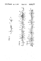
- FIG. 1 is a perspective view of an array of solar panel modules mounted, in accordance with the invention, directly to a roof surface, partially exploded and with one solar panel removed for descriptive purposes.
- FIGS. 2 and 3 are top plan and side elevation views, respectively, of the solar panel frame of the present invention.
- FIG. 4 is a sectional view of the solar panel frame as viewed along viewing line IV--IV of FIG. 2.
- FIGS. 5 and 6 are sectional views of the solar panel modules as seen, respectively, along viewing lines V--V and VI--VI of FIG. 1.
- FIG. 1 a direct mounting arrangement in which solar panel modules 10 are directly mounted to the sheathing surface 12 of a roof 14 of a building.
- Solar panel modules 10a and 10b are constructed slightly differently, as will be described, the modules including frames 16a and 16b being adapted to support three solar panels 18, it being understood that the practice of the invention is not limited to the number of panels 18 shown and described herein. In this regard, for example, one longer panel may be used instead of three separate panels.
- module 10b as shown in FIG. 1 one of the panels 18 is removed for purposes of illustration, it also being understood that in the actual construction, a panel 18 would be provided therein.
- the frames 16a and 16b are mounted on the roof surface 12 in overlapped disposition, as will be detailed, and attached thereto by suitable fasteners, such as conventional roofing nails 20.
- the frames 16a and 16b are suitably integrated with roofing shingles 22, which integration provides waterproofing protection and an aesthetically pleasing appearance.
- solar panels 18 preferably comprise a plurality of photovoltaic cells of the silicon type, formed on a transparent glass substrate with an electrically conductive layer interconnecting the individual cells into a connected array.
- Such panels are commercially available, for example, from Chronar Corp., Princeton, N.J.
- the panel 18 is installed with the transparent substrate exposed to incident radiation and with the conductive layer opposite the exposed surface.
- Frame 16b comprises an elongate, generally flat rectangular base 24 defining three substantially planar mounting surfaces 26, 28 and 30 extending longitudinally therealong. Each mounting surface 26, 28 and 30 is configured to receive and support thereon a solar panel 18 and is dimensioned in accordance with the panel size, for example, about 12 inches by 12 inches.
- a continuous upstanding ridge or wall 32 and 34 projecting transversely upwardly from the base 24.
- Walls 32 and 34 extend substantially parallel to each other and are formed to have a curved upper portion having a generally inverted U-shaped configuration, defining thereby a pair of channels 36 and 38 serving as raceways for electrical wires for the solar panel modules, as will be set forth hereinbelow.
- Extending in parallel and laterally across the base 24 adjacent its longitudinal ends 24a and 24b are a pair of upstanding continuous walls 40 and 42 defining, respectively as shown in FIG. 4, a pair of channels 44 and 46, preferably being in communication with channels 36 and 38 and also serving as wiring raceways.
- Walls 40 and 42 each comprise an inclined wall surface 40a and 42a sloping obliquely relative to the base planar surfaces.
- the side walls 32 and 34 are formed of different configuration to permit interlocking of frames along the longitudinal direction.
- wall 34 is formed to have an exterior curvature that would fit within the interior curvature of the opposing side 32 of another similarly constructed frame.
- overlapped interlocking of side-by-side frames 16a and 16b is achieved, as shown in FIG. 1.
- Lateral interlocking of frames is permitted by providing different configurations of the side walls 32 and 34 at the ends of the base 24a and 24b.
- walls 32 and 34 are stepped-down to have a portion 32a and 34a that would fit into the interior of side walls 32b and 34b at the end 24b of a similarly constructed frame.
- the frames 16a and 16b are capable of overlapping interlocking along their lateral extents, or by reference to FIG. 1, from top to bottom along the roof surface.
- each of the planar surfaces 26, 28 and 30 are recesses 48, 50 and 52, respectively, each being formed in a generally cross-like shape.
- the recesses each have, in the preferred form, a bottom wall 48a, 50a and 52a extending longitudinally in parallel with the side walls 32 and 34 and an intersecting bottom wall 48b, 50b and 52b extending laterally in parallel with the end walls 40 and 42.
- a pair of grooves 54 and 56 At the lateral edges of each of the planar surfaces 26, 28 and 30 and contiguously adjacent the side walls 32 and 34, there are a pair of grooves 54 and 56. Grooves 54 and 56 project downwardly from the planar surfaces 26, 28 and 30 and extend longitudinally along the side walls 32 and 34 between the end walls 40 and 42.
- Grooves 58 and 60 are disposed contiguously adjacent the interior portions of walls 40 and 42 and extend laterally across the base 24. Grooves 62 and 64 also extend laterally across the base 24 at spaced longitudinal positions. Grooves 58, 60, 62 and 64 each project downwardly from the planar surfaces 26, 28 and 30. As described herein and shown in the drawing, the grooves define each of the planar surfaces 26, 28 and 30 and extend fully about the periphery of each of such surfaces, the purposes for which will be detailed.
- Frame 16b has at a longitudinal edge adjacent side wall 34 a substantially flat flange 66 projecting outwardly therefrom.
- substantially flat flanges 68 and 70 extend outwardly of end walls 40 and 42, respectively.
- Wall portions 32a and 34a extend onto end flange 68 at base end 24a and wall portions 32b and 34b extend onto end flange 70 at base end 24b for the overlapping interlocking purposes described hereinabove.
- Frame 16a is constructed similar to that of frame 16b, frame 16a having, as shown in FIGS. 2 and 3, a substantially flat flange 72 extending outwardly of and longitudinally along the end wall 32.
- Frames 16a and 16b are preferably formed of a relatively lightweight, non-conductive material, such as plastic.
- the frames are of integral, molded construction for lowcost manufacture and ease of handling. It should be appreciated, however, that the frames may also be formed of a metallic material with suitable consideration given for electrical grounding.
- the solar panels 18 are installed onto the frame planar surfaces, for example, surface 26, as illustrated in FIG. 5.
- a quantity of adhesive sealant 74 which may be an uncured butyl mastic, is disposed in the grooves surrounding the planar surfaces (e.g., grooves 54, 56, 60 and 64 around surface 26).
- the panel 18 is placed onto the surface 26 such that conductive layers on the panel under surface 18a representing positive and negative terminals make electrical engagement with a pair of common bus-bars 76 and 78 suitably supported on the frame.
- the peripheral edges of the panel under surface 18a are pressed into sealed engagement with the sealant 74 until the panel under surface 18a bottoms onto the frame surface 26.
- the panel 18 is sealably secured with its upper surface 18 fully free and unencumbered for receipt of incident solar radiation. Removal of a panel 18 is simply effected with a pry-type tool whereby lifting of the panel 18 breaks the seal and allows repair or replacement thereof as well as access to the frame surface 26.
- the frames 16a and 16b are formed such that when the frames are attached to the roof surface 12, the planar surfaces 26, 28 and 30 are spaced upwardly from the roof surface 12 defining thereby a cavity 80 between the frame surfaces and the roof. This is achieved by spacing the flanges, e.g., flanges 72 and 66, to extend in a common plane 82 that is substantially parallel to the planar surface 26 but spaced downwardly therefrom.
- the bottom walls of the recesses e.g., bottom wall 48a (FIG. 5), are likewise formed to extend in the common plane 82.
- the panel support is very strong. This type of support is desirable, as in installation or repair it may become necessary for a work person to walk directly on the panels.
- the panel support structure as set forth herein together with the flexible properties of a plastic frame capable of absorbing such loads, enables one to walk on the solar panels without causing breakage thereof.
- Electrical connection from the bus bars 76 and 78 is effected by routing electrical wires 84 and 86 (FIG. 1) through openings 88 and 90 in the frames, e.g., through a wall of recesses 48, 50, 52. Sealants 92 and 94 disposed in the recess may be used to seal the openings 88 and 90. Additionally, a diode 96 may be interconnected in the recess between the wires 84 and 86 to prevent a backflow of current through the circuit in the event a short develops in the solar panel 18. As depicted in FIG.
- the wires 84 and 86 are passed beneath the planar surface 26 through cavity 80 and respectively into the channels 36 and 38 defined by the side walls 32 and 34, channels 36 and 38 communicating with the cavity 80 as the bottom walls of the grooves 54-64 are preferably spaced upwardly of the plane 82.
- the wires 84 and 86 of each module may be interconnected, preferably by means of a conventional waterproof disconnect 98. As such, connection of the appropriate positive and negative terminals of adjoining modules established a suitable electrical circuit for an array of interconnected solar panel modules.
- the disconnects 98 and interconnected wires are concealed in a raceway when another module is installed. Where no connections are made to various wires, the wires are placed within a raceway and the raceway is suitably sealed. Also, it should be appreciated that the planar surfaces, e.g., surfaces 26, 28 and 30, serve as a barrier wall by which with suitable sealing the electrical connections to the solar panels 18 are isolated from the network of wiring extending beneath such planar surfaces and extending into the raceways.
- the advantages of the frame interlocking aspects of the presently described module may be seen.
- the end wall 32 of the frame 16b overlappingly receives the smaller end wall 34 of the frame 16a along its longitudinal extent.
- the interface between the overlapped walls, as shown in FIG. 5, may be filled with a sealant 100 for moisture protection as well as adhesion.
- the overlapped interlock permits the edges of each of the adjacent solar panels 18 to be relatively close, spaced only by the width of the walls 32, 34, thereby providing a high density solar panel mounting.
- FIG. 6 The interlocking of solar panel modules along the lateral extents, or top to bottom of the frames, is shown in FIG. 6.
- the stepped-down wall portion 32b is received within the wall end portion 32a of the upper or lower adjoining frame.
- a suitable sealant 102 may be provided for sealing and securing the overlapping portions at their interfaces.
- Sloping wall surface 40a which, for example, would be facing toward the top of the roof 14, provides a rain runoff surface, preventing undesirable water accumulation around the panels 18.
- the direct mounting approach provides for a very low profile mounting structure which may be readily used for new installations or building retrofits.
- the frames as described herein serve, in effect, as shingles themselves whereby the mounting flanges are secured directly to the roof sheathing.
- the flanges also serve as flashing upon integration with surrounding shingles for additional moisture-proofing.
- the overlapping interlocking features of the frames provide ease of assembly, sealing and a design capable of high density panel mounting.
- the concealed raceways for the electrical wiring not only hide the wires but due to their concealment enhance the safety of the system.
- the removable panels, sealed from underneath, provides full surface radiation receipt and facilitates maintenance, repair and panel replacement without need for dismantling the entire module.
- the panel removability provides access to the module frame for repair, if necessary, of electrical components such as the diode or wires.
- the frame construction which provides nearly a full backing support surface for each of the panels as well as strengthening members providing additional support to the interior undersurface of the panels is sufficiently strong for a work person to walk thereon.
Abstract
Description
Claims (8)
Priority Applications (4)
| Application Number | Priority Date | Filing Date | Title |
|---|---|---|---|
| US06/527,439 US4636577A (en) | 1983-08-29 | 1983-08-29 | Solar panel module and support therefor |
| CA000460957A CA1248582A (en) | 1983-08-29 | 1984-08-14 | Solar panel module and support therefor |
| EP84305656A EP0137666A3 (en) | 1983-08-29 | 1984-08-20 | Solar panel module and support therefor |
| JP59178535A JPS6089986A (en) | 1983-08-29 | 1984-08-29 | Solar panel module and its support |
Applications Claiming Priority (1)
| Application Number | Priority Date | Filing Date | Title |
|---|---|---|---|
| US06/527,439 US4636577A (en) | 1983-08-29 | 1983-08-29 | Solar panel module and support therefor |
Publications (1)
| Publication Number | Publication Date |
|---|---|
| US4636577A true US4636577A (en) | 1987-01-13 |
Family
ID=24101469
Family Applications (1)
| Application Number | Title | Priority Date | Filing Date |
|---|---|---|---|
| US06/527,439 Expired - Fee Related US4636577A (en) | 1983-08-29 | 1983-08-29 | Solar panel module and support therefor |
Country Status (4)
| Country | Link |
|---|---|
| US (1) | US4636577A (en) |
| EP (1) | EP0137666A3 (en) |
| JP (1) | JPS6089986A (en) |
| CA (1) | CA1248582A (en) |
Cited By (113)
| Publication number | Priority date | Publication date | Assignee | Title |
|---|---|---|---|---|
| US5164020A (en) * | 1991-05-24 | 1992-11-17 | Solarex Corporation | Solar panel |
| WO1993014525A1 (en) * | 1992-01-16 | 1993-07-22 | United Solar Systems Corporation | Photovoltaic roof system |
| US5252141A (en) * | 1991-02-20 | 1993-10-12 | Canon Kabushiki Kaisha | Modular solar cell with protective member |
| US5289999A (en) * | 1990-07-04 | 1994-03-01 | Schottel Werft Joseph Becker Gmbh & Co. Kg | Apparatus for mounting solar cells |
| US5290366A (en) * | 1990-03-08 | 1994-03-01 | Siemens Solar Gmh | Laminated solar module |
| US5338369A (en) * | 1993-02-16 | 1994-08-16 | Rawlings Lyle K | Roof-integratable photovolatic modules |
| US5409549A (en) * | 1992-09-03 | 1995-04-25 | Canon Kabushiki Kaisha | Solar cell module panel |
| AT400057B (en) * | 1991-12-23 | 1995-09-25 | Sedelmayer Roland Ing | PHOTOVOLTAIC SOLAR PANEL TO BE ARRANGED ON A ROOF |
| US5509973A (en) * | 1993-04-08 | 1996-04-23 | Misawa Homes Co., Ltd. | Roof panel and roof structure with solar batteries |
| US5531049A (en) * | 1989-03-30 | 1996-07-02 | Hirai Engineering Corporation | Roof mounted light transmitting frame |
| US5571338A (en) * | 1993-11-26 | 1996-11-05 | Sanyo Electric Co., Ltd. | Photovoltaic module and a photovoltaic apparatus |
| DE19521098A1 (en) * | 1995-06-09 | 1996-12-12 | Wilfried Bonn | Roof tile with photoelectric cells or solar tile |
| WO2000012839A1 (en) * | 1998-08-31 | 2000-03-09 | Pacific Solar Pty. Ltd. | Panel mounting frame and method |
| US6155006A (en) * | 1996-08-30 | 2000-12-05 | Canon Kabushiki Kaisha | Horizontal-roofing and mounting method thereof |
| US6182404B1 (en) * | 1996-03-29 | 2001-02-06 | Lafarge Braas Gmbh | Sub-roofing element, on a roof, for a flat, plate-shaped structural element |
| US6201179B1 (en) * | 1997-10-03 | 2001-03-13 | Nick Dalacu | Array of photovoltaic modules for an integrated solar power collector system |
| US6245987B1 (en) * | 1997-09-10 | 2001-06-12 | Canon Kabushiki Kaisha | Solar cell module, enclosure with solar cells, enclosure installation method, and solar cell system |
| US6354289B1 (en) * | 1994-09-01 | 2002-03-12 | Envirotech Investments Limited | Ambient heat collection panels |
| US6365824B1 (en) * | 1999-07-21 | 2002-04-02 | Kaneka Corporation | Roof tile-cum-solar battery module |
| US6498289B1 (en) * | 1996-08-08 | 2002-12-24 | Canon Kabushiki Kaisha | Solar battery module and roofing material incorporating it |
| WO2003007688A2 (en) * | 2001-07-20 | 2003-01-30 | Unirac, Inc. | A system for removably and adjustably mounting a device on a surface |
| AU757134B2 (en) * | 1998-08-31 | 2003-02-06 | Pacific Solar Pty Limited | Panel mounting frame and method |
| US20040011354A1 (en) * | 2000-04-04 | 2004-01-22 | Erling Peter Stuart | Framing system for solar panels |
| US20040144043A1 (en) * | 2003-01-23 | 2004-07-29 | Stevenson Edward J | Integrated photovoltaic roofing component and panel |
| US20050072456A1 (en) * | 2003-01-23 | 2005-04-07 | Stevenson Edward J. | Integrated photovoltaic roofing system |
| US20050126621A1 (en) * | 2003-08-20 | 2005-06-16 | Powerlight Corporation | PV wind performance enhancing methods and apparatus |
| US20050144903A1 (en) * | 2003-12-23 | 2005-07-07 | Isolpack S.P.A. | Insulating panel for building purposes |
| US20050161074A1 (en) * | 2003-12-16 | 2005-07-28 | Paul Garvison | Photovoltaic module mounting unit and system |
| US20060086382A1 (en) * | 2004-02-13 | 2006-04-27 | Plaisted Joshua R | Mechanism for mounting solar modules |
| US20060090788A1 (en) * | 2004-11-02 | 2006-05-04 | Eugene Oak | Super structure for roof patio solar plant |
| US20060266352A1 (en) * | 2005-05-31 | 2006-11-30 | Finley Shapiro Consulting, Inc. | Self-ballasting solar array mount |
| US20070028958A1 (en) * | 2005-08-05 | 2007-02-08 | Retti Kahrl L | Multiple layer solar energy harvesting composition and method, solar energy harvesting buckyball, inductive coupling device; vehicle chassis; atmospheric intake hydrogen motor; electrical energy generating tire; and mechanical energy harvesting device |
| US20070193618A1 (en) * | 2005-09-19 | 2007-08-23 | Solar Roofing Systems, Inc. | Integrated Solar Roofing System |
| US20070251567A1 (en) * | 2004-02-13 | 2007-11-01 | Plaisted Joshua R | Interconnected solar module design and system |
| US20080000174A1 (en) * | 2006-06-30 | 2008-01-03 | Lumeta, Inc. | Profile roof tile with integrated photovoltaic module |
| US20080000512A1 (en) * | 2006-06-30 | 2008-01-03 | Dri Energy Corporation | Profile roof tile with integrated photovoltaic module |
| US20080053009A1 (en) * | 2006-09-06 | 2008-03-06 | Joshua Reed Plaisted | Strut runner member and assembly using same for mounting arrays on rooftops and other structures |
| US20080053517A1 (en) * | 2006-08-31 | 2008-03-06 | Joshua Reed Plaisted | Technique for electrically bonding solar modules and mounting assemblies |
| US20080121273A1 (en) * | 2006-11-29 | 2008-05-29 | Joshua Reed Plaisted | Mounting assembly for arrays and other surface-mounted equipment |
| US20080149168A1 (en) * | 2006-12-22 | 2008-06-26 | Dri Solar Corporation | Photovoltaic module for roofs |
| US20080149169A1 (en) * | 2006-12-22 | 2008-06-26 | Lumeta, Inc. | Photovoltaic module for roofs |
| US20090038668A1 (en) * | 2007-08-08 | 2009-02-12 | Joshua Reed Plaisted | Topologies, systems and methods for control of solar energy supply systems |
| US20090205703A1 (en) * | 2008-02-14 | 2009-08-20 | Applied Materials, Inc. | Apparatus and method of mounting and supporting a solar panel |
| US20090255530A1 (en) * | 2008-04-14 | 2009-10-15 | Abt, Inc. | Apparatus for mounting a solar panel and method and apparatus for forming the mounting apparatus |
| US20100000596A1 (en) * | 2008-07-02 | 2010-01-07 | Laurence Mackler | Solar Power Generation Assembly and Method for Providing Same |
| US20100071310A1 (en) * | 2008-09-23 | 2010-03-25 | Joe Brescia | Method of Assembling Building Integrated Photovoltaic Conversion System |
| US20100126087A1 (en) * | 2008-11-13 | 2010-05-27 | Joe Brescia | Plank Based Photovoltaic Conversion System |
| DE202010004663U1 (en) | 2010-04-07 | 2010-08-12 | Alexeev, Alexey V. | Flexible photoelectric module |
| US20100212722A1 (en) * | 2009-02-24 | 2010-08-26 | Wares Brian S | Photovoltaic Module and Interlocked Stack of Photovoltaic Modules |
| US20100236542A1 (en) * | 2009-03-18 | 2010-09-23 | The Garland Company, Inc. | Solar roofing system |
| US7856769B2 (en) | 2004-02-13 | 2010-12-28 | Pvt Solar, Inc. | Rack assembly for mounting solar modules |
| US20110017198A1 (en) * | 2007-05-10 | 2011-01-27 | Pvstrom Gmbh & Co. Kg | Carrier system for a trackable solar energy plant and a kit |
| US20110073163A1 (en) * | 2009-09-25 | 2011-03-31 | Osbert Hay Cheung | Photovoltaic lamination and roof mounting systems |
| US20110232212A1 (en) * | 2009-03-18 | 2011-09-29 | Garland Industries, Inc. | Solar roofing system |
| US20110302859A1 (en) * | 2010-06-14 | 2011-12-15 | Institut De Recherche Fondamentale En Technologies Solaires - IRFTS | Structure for rigidly connecting solar panels to a fixture |
| US20110314751A1 (en) * | 2010-06-29 | 2011-12-29 | Roger Jette | Solar panel mounting rack system |
| US20120137600A1 (en) * | 2010-09-28 | 2012-06-07 | Jenkins Robert L | Photovoltaic Systems, methods For Installing Photovoltaic Systems, And Kits For Installing Photovoltaic Systems |
| US8307606B1 (en) | 2011-07-07 | 2012-11-13 | Solon Corporation | Integrated photovoltaic rooftop modules |
| US20120291848A1 (en) * | 2011-05-16 | 2012-11-22 | Miasole | Supporting structures for building integrable photovoltaic modules |
| US20120312373A1 (en) * | 2011-06-10 | 2012-12-13 | Decra Roofing Systems, Inc. | Solar Roof Panel Assembly and Method for Installation |
| US8413391B2 (en) | 2008-10-13 | 2013-04-09 | Sunlink Corporation | Solar array mounting system with universal clamp |
| US20130111831A1 (en) * | 2011-11-03 | 2013-05-09 | Robert L. Jenkins | Photovoltaic Roofing Systems And Methods For Repairing Them |
| WO2013096962A1 (en) * | 2011-12-23 | 2013-06-27 | Solarworld Usa | A roof panel for supporting pv modules |
| US8601755B2 (en) | 2011-03-28 | 2013-12-10 | 1541689 Ontario Inc. | Solar panel supports |
| US8640400B2 (en) | 2003-02-26 | 2014-02-04 | Unirac, Inc. | Low profile mounting system |
| US8646228B2 (en) | 2009-03-24 | 2014-02-11 | Certainteed Corporation | Photovoltaic systems, methods for installing photovoltaic systems, and kits for installing photovoltaic systems |
| US20140083028A1 (en) * | 2011-05-10 | 2014-03-27 | Robert Richardson | Roof solar panel for conventional sloping roof and shingle integration |
| US8919075B2 (en) | 2011-03-15 | 2014-12-30 | Richard William Erickson | Unitized photovoltaic assembly |
| US9038329B2 (en) | 2011-10-11 | 2015-05-26 | Sunlink Corporation | Structure following roof mounted photovoltaic system |
| US9263985B2 (en) | 2012-11-13 | 2016-02-16 | Pi Solar Technology Gmbh | Rooftop photovoltaic modules |
| US9279415B1 (en) | 2005-07-07 | 2016-03-08 | Sunlink Corporation | Solar array integration system and methods therefor |
| USD751976S1 (en) | 2013-08-05 | 2016-03-22 | Sunpower Corporation | Solar power generation assembly |
| USD754064S1 (en) | 2013-08-05 | 2016-04-19 | Sunpower Corporation | Solar power generation assembly |
| USD774450S1 (en) | 2013-08-05 | 2016-12-20 | Sunpower Corporation | Photovoltaic sundial assembly |
| US20170077866A1 (en) * | 2015-09-14 | 2017-03-16 | Vivint Solar, Inc. | Solar module mounting |
| US9628019B1 (en) | 2016-09-09 | 2017-04-18 | Polar Racking Inc. | Photovoltaic panel racking system |
| US9973143B1 (en) | 2016-09-01 | 2018-05-15 | Daniel J Courselle | Solar panel roof modules |
| USD819137S1 (en) | 2013-08-05 | 2018-05-29 | Sunpower Corporation | Column cover |
| NL2018277B1 (en) * | 2017-02-01 | 2018-08-22 | Isobouw Systems Bv | System for installing solar panels on a sloping roof. |
| US20190044471A1 (en) * | 2016-02-05 | 2019-02-07 | Lonnie L. Kornovich | Utility Pole Mounted Solar Panels and Securing Brackets |
| US10243505B1 (en) | 2016-03-07 | 2019-03-26 | Raceway Racking, Inc. | Wire management racking system for photovoltaic solar modules |
| USRE47733E1 (en) | 2004-02-05 | 2019-11-19 | Tesla, Inc. | Method and apparatus for mounting photovoltaic modules |
| US10505492B2 (en) * | 2016-02-12 | 2019-12-10 | Solarcity Corporation | Building integrated photovoltaic roofing assemblies and associated systems and methods |
| US20200204108A1 (en) * | 2018-12-20 | 2020-06-25 | Hall Labs Llc | Electrical and mechanical roof underlayment |
| RU199985U1 (en) * | 2020-07-07 | 2020-10-01 | Акционерное общество "Научно-производственный комплекс "Дедал" | Device for fastening spring-loaded photovoltaic modules |
| US11012024B2 (en) | 2018-07-03 | 2021-05-18 | Building Materials Investment Corporation | Roof integrated photovoltaic system with improved serviceability |
| US11233479B2 (en) * | 2018-05-04 | 2022-01-25 | Sunpower Corporation | Cabling systems for rooftop photovoltaic solar systems |
| US11251744B1 (en) | 2020-06-04 | 2022-02-15 | GAF Energy LLC | Photovoltaic shingles and methods of installing same |
| US11283394B2 (en) | 2020-02-18 | 2022-03-22 | GAF Energy LLC | Photovoltaic module with textured superstrate providing shingle-mimicking appearance |
| US11309828B2 (en) | 2019-11-27 | 2022-04-19 | GAF Energy LLC | Roof integrated photovoltaic module with spacer |
| US11398795B2 (en) | 2019-12-20 | 2022-07-26 | GAF Energy LLC | Roof integrated photovoltaic system |
| US11424379B2 (en) | 2020-04-30 | 2022-08-23 | GAF Energy LLC | Photovoltaic module frontsheet and backsheet |
| US11431281B2 (en) | 2020-02-27 | 2022-08-30 | GAF Energy LLC | Photovoltaic module with light-scattering encapsulant providing shingle-mimicking appearance |
| US11444569B2 (en) | 2020-10-14 | 2022-09-13 | GAF Energy LLC | Mounting apparatus for photovoltaic modules |
| US11454027B2 (en) | 2020-10-29 | 2022-09-27 | GAF Energy LLC | System of roofing and photovoltaic shingles and methods of installing same |
| US11459757B2 (en) | 2021-01-19 | 2022-10-04 | GAF Energy LLC | Watershedding features for roofing shingles |
| US11486144B2 (en) | 2020-11-12 | 2022-11-01 | GAF Energy LLC | Roofing shingles with handles |
| US11489482B2 (en) | 2020-01-22 | 2022-11-01 | GAF Energy LLC | Integrated photovoltaic roofing shingles, methods, systems, and kits thereof |
| US11496088B2 (en) | 2021-02-19 | 2022-11-08 | GAF Energy LLC | Photovoltaic module for a roof with continuous fiber tape |
| US11508861B1 (en) | 2021-06-02 | 2022-11-22 | GAF Energy LLC | Photovoltaic module with light-scattering encapsulant providing shingle-mimicking appearance |
| US11512480B1 (en) | 2021-07-16 | 2022-11-29 | GAF Energy LLC | Roof material storage bracket |
| US11527665B2 (en) | 2021-05-06 | 2022-12-13 | GAF Energy LLC | Photovoltaic module with transparent perimeter edges |
| US11545928B2 (en) | 2020-10-13 | 2023-01-03 | GAF Energy LLC | Solar roofing system |
| US11545927B2 (en) | 2020-04-09 | 2023-01-03 | GAF Energy LLC | Three-dimensional laminate photovoltaic module |
| US11601085B2 (en) * | 2015-11-02 | 2023-03-07 | Certainteed Llc | Photovoltaic roofing systems with bottom flashings |
| US11658470B2 (en) | 2020-05-13 | 2023-05-23 | GAF Energy LLC | Electrical cable passthrough |
| US11728759B2 (en) | 2021-09-01 | 2023-08-15 | GAF Energy LLC | Photovoltaic modules for commercial roofing |
| US11811361B1 (en) | 2022-12-14 | 2023-11-07 | GAF Energy LLC | Rapid shutdown device for photovoltaic modules |
| US11824487B2 (en) | 2020-11-13 | 2023-11-21 | GAF Energy LLC | Photovoltaic module systems and methods |
| US11824486B2 (en) | 2022-01-20 | 2023-11-21 | GAF Energy LLC | Roofing shingles for mimicking the appearance of photovoltaic modules |
| US11843067B2 (en) | 2020-07-22 | 2023-12-12 | GAF Energy LLC | Photovoltaic modules |
| US11870227B2 (en) | 2020-09-03 | 2024-01-09 | GAF Energy LLC | Building integrated photovoltaic system |
| US11961928B2 (en) | 2022-07-29 | 2024-04-16 | GAF Energy LLC | Photovoltaic module with light-scattering encapsulant providing shingle-mimicking appearance |
Families Citing this family (15)
| Publication number | Priority date | Publication date | Assignee | Title |
|---|---|---|---|---|
| US5092939A (en) * | 1990-11-30 | 1992-03-03 | United Solar Systems Corporation | Photovoltaic roof and method of making same |
| WO1992016972A1 (en) * | 1991-03-13 | 1992-10-01 | Bainbridge Philip David Sebast | Cladding system for solar tiles |
| JPH0823116A (en) * | 1994-07-07 | 1996-01-23 | Sunstar Eng Inc | Solar cell module and its manufacture |
| DE4433769A1 (en) * | 1994-09-22 | 1996-03-28 | Blue Planet Ag | Process for attaching solar panels |
| US7642449B2 (en) * | 2004-08-24 | 2010-01-05 | General Electric Company | Photovoltaic integrated building component |
| US8196360B2 (en) | 2006-01-12 | 2012-06-12 | Msr Innovations Inc. | Photovoltaic solar roof tile assembly system |
| FR2918397A1 (en) * | 2007-07-06 | 2009-01-09 | Terreal Soc Par Actions Simpli | DEVICE FOR INTEGRATING SOLAR PANEL ON A ROOF, PARTICULARLY FOR PHOTOVOLTAIC SOLAR. |
| SG152074A1 (en) * | 2007-10-09 | 2009-05-29 | Dragon Energy Pte Ltd | Roof based energy conversion system |
| US8209920B2 (en) | 2007-11-06 | 2012-07-03 | Certain Teed Corporation | Photovoltaic roofing systems and methods for installing them |
| FR2932830B1 (en) * | 2008-06-18 | 2013-04-26 | Noelle Environnement | IMPROVING THE MEDIA FOR THE INSTALLATION OF PHOTOVOLTAIC PANELS |
| DE102008051002A1 (en) * | 2008-07-25 | 2010-02-04 | Thermovolt Ag | Metal lightweight roof construction with integrated photovoltaic module |
| DE102008037734A1 (en) * | 2008-08-14 | 2010-02-18 | Ralos Vertriebs Gmbh | Solar module for a solar system, in particular photovoltaic system |
| ITMI20091383A1 (en) * | 2009-07-31 | 2011-02-01 | Massimo Gianfranco Donini | MODULAR SYSTEM FOR THE ASSEMBLY OF PHOTOVOLTAIC PANELS |
| DE102011055754B4 (en) * | 2011-06-01 | 2022-12-29 | Fraunhofer-Gesellschaft zur Förderung der angewandten Forschung e.V. | Solar cell module and method for connecting solar cells |
| EP2674987B1 (en) * | 2012-06-13 | 2018-02-07 | Zagsolar AG | Module holder for solar modules and assembly with multiple module holders |
Citations (15)
| Publication number | Priority date | Publication date | Assignee | Title |
|---|---|---|---|---|
| US25647A (en) * | 1859-10-04 | Mode of disinfecting eeathees | ||
| US3411952A (en) * | 1962-04-02 | 1968-11-19 | Globe Union Inc | Photovoltaic cell and solar cell panel |
| US3565719A (en) * | 1967-05-17 | 1971-02-23 | Nasa | Solar panel fabrication |
| US3620847A (en) * | 1969-05-05 | 1971-11-16 | Us Air Force | Silicon solar cell array hardened to space nuclear blast radiation |
| US4106952A (en) * | 1977-09-09 | 1978-08-15 | Kravitz Jerome H | Solar panel unit |
| US4149025A (en) * | 1977-11-16 | 1979-04-10 | Vasile Niculescu | Method of fabricating thermoelectric power generator modules |
| US4204523A (en) * | 1976-09-11 | 1980-05-27 | E. Cacarda Gmbh | Mount for solar collectors |
| US4233085A (en) * | 1979-03-21 | 1980-11-11 | Photon Power, Inc. | Solar panel module |
| US4238912A (en) * | 1978-03-27 | 1980-12-16 | Solar Thermal Consultants Pty. Limited | Roofing systems |
| US4241727A (en) * | 1978-11-06 | 1980-12-30 | Toti Andrew J | Structural assembly, method of forming same, and elongated panel structure resulting therefrom |
| US4246892A (en) * | 1978-05-17 | 1981-01-27 | Waiche Meir R | Solar energy collector panel |
| US4327707A (en) * | 1979-11-20 | 1982-05-04 | The United States Of America As Represented By The United States Department Of Energy | Solar collector |
| US4345587A (en) * | 1979-11-16 | 1982-08-24 | D G Shelter Products Company | Solar energy collector means and method of assembling the same |
| US4392009A (en) * | 1981-10-16 | 1983-07-05 | Exxon Research And Engineering Co. | Solar power module |
| US4470406A (en) * | 1981-05-14 | 1984-09-11 | Redland Roof Tiles Limited | Roofing tile with thermal conduction device |
Family Cites Families (6)
| Publication number | Priority date | Publication date | Assignee | Title |
|---|---|---|---|---|
| US3881505A (en) * | 1974-03-04 | 1975-05-06 | Vapor Corp | Pressure responsive pilot valve |
| JPS5423489A (en) * | 1977-07-25 | 1979-02-22 | Japan Solar Energy | Solar optical generator |
| US4262411A (en) * | 1977-09-08 | 1981-04-21 | Photon Power, Inc. | Method of making a solar cell array |
| US4232070A (en) * | 1978-11-07 | 1980-11-04 | Trw Inc. | Non-arcing dielectric modular array |
| EP0026808B1 (en) * | 1979-08-30 | 1983-12-21 | Kabel- und Metallwerke Gutehoffnungshütte Aktiengesellschaft | Roof covering or façade lining and method for the manufacture of a panel for this roof covering or façade lining |
| FR2535766A1 (en) * | 1982-11-05 | 1984-05-11 | Fremont Claude | Cladding panel. |
-
1983
- 1983-08-29 US US06/527,439 patent/US4636577A/en not_active Expired - Fee Related
-
1984
- 1984-08-14 CA CA000460957A patent/CA1248582A/en not_active Expired
- 1984-08-20 EP EP84305656A patent/EP0137666A3/en not_active Withdrawn
- 1984-08-29 JP JP59178535A patent/JPS6089986A/en active Pending
Patent Citations (15)
| Publication number | Priority date | Publication date | Assignee | Title |
|---|---|---|---|---|
| US25647A (en) * | 1859-10-04 | Mode of disinfecting eeathees | ||
| US3411952A (en) * | 1962-04-02 | 1968-11-19 | Globe Union Inc | Photovoltaic cell and solar cell panel |
| US3565719A (en) * | 1967-05-17 | 1971-02-23 | Nasa | Solar panel fabrication |
| US3620847A (en) * | 1969-05-05 | 1971-11-16 | Us Air Force | Silicon solar cell array hardened to space nuclear blast radiation |
| US4204523A (en) * | 1976-09-11 | 1980-05-27 | E. Cacarda Gmbh | Mount for solar collectors |
| US4106952A (en) * | 1977-09-09 | 1978-08-15 | Kravitz Jerome H | Solar panel unit |
| US4149025A (en) * | 1977-11-16 | 1979-04-10 | Vasile Niculescu | Method of fabricating thermoelectric power generator modules |
| US4238912A (en) * | 1978-03-27 | 1980-12-16 | Solar Thermal Consultants Pty. Limited | Roofing systems |
| US4246892A (en) * | 1978-05-17 | 1981-01-27 | Waiche Meir R | Solar energy collector panel |
| US4241727A (en) * | 1978-11-06 | 1980-12-30 | Toti Andrew J | Structural assembly, method of forming same, and elongated panel structure resulting therefrom |
| US4233085A (en) * | 1979-03-21 | 1980-11-11 | Photon Power, Inc. | Solar panel module |
| US4345587A (en) * | 1979-11-16 | 1982-08-24 | D G Shelter Products Company | Solar energy collector means and method of assembling the same |
| US4327707A (en) * | 1979-11-20 | 1982-05-04 | The United States Of America As Represented By The United States Department Of Energy | Solar collector |
| US4470406A (en) * | 1981-05-14 | 1984-09-11 | Redland Roof Tiles Limited | Roofing tile with thermal conduction device |
| US4392009A (en) * | 1981-10-16 | 1983-07-05 | Exxon Research And Engineering Co. | Solar power module |
Non-Patent Citations (6)
| Title |
|---|
| "A Shakedown Shapes Up in Photovoltaics"--Chemical Week--2/3/82--p. 33. |
| A Shakedown Shapes Up in Photovoltaics Chemical Week 2/3/82 p. 33. * |
| E. J. Stefanides Central States Editor Connectors Cut Solar Electric Wiring Costs Design News 2/21/83 pp. 100 101. * |
| E. J. Stefanides--Central States Editor--"Connectors Cut Solar Electric Wiring Costs"--Design News--2/21/83--pp. 100-101. |
| Roy Gibson and Theodore Swanson MIT Industrial Liaison Program 1983. * |
| Roy Gibson and Theodore Swanson--MIT Industrial Liaison Program--1983. |
Cited By (220)
| Publication number | Priority date | Publication date | Assignee | Title |
|---|---|---|---|---|
| US5531049A (en) * | 1989-03-30 | 1996-07-02 | Hirai Engineering Corporation | Roof mounted light transmitting frame |
| US5290366A (en) * | 1990-03-08 | 1994-03-01 | Siemens Solar Gmh | Laminated solar module |
| US5289999A (en) * | 1990-07-04 | 1994-03-01 | Schottel Werft Joseph Becker Gmbh & Co. Kg | Apparatus for mounting solar cells |
| US5232518A (en) * | 1990-11-30 | 1993-08-03 | United Solar Systems Corporation | Photovoltaic roof system |
| US5252141A (en) * | 1991-02-20 | 1993-10-12 | Canon Kabushiki Kaisha | Modular solar cell with protective member |
| US5164020A (en) * | 1991-05-24 | 1992-11-17 | Solarex Corporation | Solar panel |
| AT400057B (en) * | 1991-12-23 | 1995-09-25 | Sedelmayer Roland Ing | PHOTOVOLTAIC SOLAR PANEL TO BE ARRANGED ON A ROOF |
| WO1993014525A1 (en) * | 1992-01-16 | 1993-07-22 | United Solar Systems Corporation | Photovoltaic roof system |
| US5409549A (en) * | 1992-09-03 | 1995-04-25 | Canon Kabushiki Kaisha | Solar cell module panel |
| US5338369A (en) * | 1993-02-16 | 1994-08-16 | Rawlings Lyle K | Roof-integratable photovolatic modules |
| US5509973A (en) * | 1993-04-08 | 1996-04-23 | Misawa Homes Co., Ltd. | Roof panel and roof structure with solar batteries |
| US5571338A (en) * | 1993-11-26 | 1996-11-05 | Sanyo Electric Co., Ltd. | Photovoltaic module and a photovoltaic apparatus |
| US6354289B1 (en) * | 1994-09-01 | 2002-03-12 | Envirotech Investments Limited | Ambient heat collection panels |
| DE19521098A1 (en) * | 1995-06-09 | 1996-12-12 | Wilfried Bonn | Roof tile with photoelectric cells or solar tile |
| US6182404B1 (en) * | 1996-03-29 | 2001-02-06 | Lafarge Braas Gmbh | Sub-roofing element, on a roof, for a flat, plate-shaped structural element |
| US6498289B1 (en) * | 1996-08-08 | 2002-12-24 | Canon Kabushiki Kaisha | Solar battery module and roofing material incorporating it |
| US6336304B1 (en) | 1996-08-30 | 2002-01-08 | Canon Kabushiki Kaisha | Horizontal-roofing roof and mounting method thereof |
| US6155006A (en) * | 1996-08-30 | 2000-12-05 | Canon Kabushiki Kaisha | Horizontal-roofing and mounting method thereof |
| US6245987B1 (en) * | 1997-09-10 | 2001-06-12 | Canon Kabushiki Kaisha | Solar cell module, enclosure with solar cells, enclosure installation method, and solar cell system |
| US6201179B1 (en) * | 1997-10-03 | 2001-03-13 | Nick Dalacu | Array of photovoltaic modules for an integrated solar power collector system |
| EP1112423A1 (en) * | 1998-08-31 | 2001-07-04 | Pacific Solar Pty Ltd | Panel mounting frame and method |
| EP1112423A4 (en) * | 1998-08-31 | 2004-12-29 | Pacific Solar Pty Ltd | Panel mounting frame and method |
| WO2000012839A1 (en) * | 1998-08-31 | 2000-03-09 | Pacific Solar Pty. Ltd. | Panel mounting frame and method |
| AU757134B2 (en) * | 1998-08-31 | 2003-02-06 | Pacific Solar Pty Limited | Panel mounting frame and method |
| US6365824B1 (en) * | 1999-07-21 | 2002-04-02 | Kaneka Corporation | Roof tile-cum-solar battery module |
| US7012188B2 (en) * | 2000-04-04 | 2006-03-14 | Peter Stuart Erling | Framing system for solar panels |
| US20040011354A1 (en) * | 2000-04-04 | 2004-01-22 | Erling Peter Stuart | Framing system for solar panels |
| WO2003007688A3 (en) * | 2001-07-20 | 2003-10-02 | Unirac Inc | A system for removably and adjustably mounting a device on a surface |
| US8763968B2 (en) | 2001-07-20 | 2014-07-01 | Unirac, Inc. | System for mounting a photovoltaic module to a surface |
| GB2394969A (en) * | 2001-07-20 | 2004-05-12 | Unirac Inc | A system for removably and adjustably mounting a device on a surface |
| US7434362B2 (en) * | 2001-07-20 | 2008-10-14 | Unirac, Inc. | System for removably and adjustably mounting a device on a surface |
| US8128044B2 (en) | 2001-07-20 | 2012-03-06 | Unirac, Inc. | System for mounting a photovoltaic module to a surface |
| WO2003007688A2 (en) * | 2001-07-20 | 2003-01-30 | Unirac, Inc. | A system for removably and adjustably mounting a device on a surface |
| US20080010915A1 (en) * | 2001-07-20 | 2008-01-17 | Unirac, Inc | Apparatus and method for positioning a module on an object |
| GB2394969B (en) * | 2001-07-20 | 2005-09-21 | Unirac Inc | A system for removably and adjustably mounting a device on a surface |
| US20100293874A1 (en) * | 2001-07-20 | 2010-11-25 | Unirac, Inc. | system for mounting a photovoltaic module to a surface |
| US7766292B2 (en) | 2001-07-20 | 2010-08-03 | Unirac, Inc. | System for mounting a photovoltaic module to a surface |
| US20050072456A1 (en) * | 2003-01-23 | 2005-04-07 | Stevenson Edward J. | Integrated photovoltaic roofing system |
| US20040144043A1 (en) * | 2003-01-23 | 2004-07-29 | Stevenson Edward J | Integrated photovoltaic roofing component and panel |
| US20080121267A1 (en) * | 2003-01-23 | 2008-05-29 | Solar Integrated Technologies, Inc. | Integrated photovoltaic roofing component and panel |
| US7342171B2 (en) | 2003-01-23 | 2008-03-11 | Solar Intergrated Technologies, Inc. | Integrated photovoltaic roofing component and panel |
| US8640400B2 (en) | 2003-02-26 | 2014-02-04 | Unirac, Inc. | Low profile mounting system |
| US20050126621A1 (en) * | 2003-08-20 | 2005-06-16 | Powerlight Corporation | PV wind performance enhancing methods and apparatus |
| US20050161074A1 (en) * | 2003-12-16 | 2005-07-28 | Paul Garvison | Photovoltaic module mounting unit and system |
| US20050144903A1 (en) * | 2003-12-23 | 2005-07-07 | Isolpack S.P.A. | Insulating panel for building purposes |
| US7469508B2 (en) | 2003-12-23 | 2008-12-30 | Isolpack S.P.A. | Insulating panel and photovoltaic module for building purposes |
| EP1548202A3 (en) * | 2003-12-23 | 2006-04-19 | Isolpack S.p.A. | An insulating panel for building purposes |
| USRE47733E1 (en) | 2004-02-05 | 2019-11-19 | Tesla, Inc. | Method and apparatus for mounting photovoltaic modules |
| US20110210085A1 (en) * | 2004-02-13 | 2011-09-01 | Joshua Reed Plaisted | Interconnected solar module design and system |
| US20110174360A1 (en) * | 2004-02-13 | 2011-07-21 | Joshua Reed Plaisted | Rack assembly for mounting solar modules |
| US7900407B2 (en) | 2004-02-13 | 2011-03-08 | Pvt Solar, Inc. | Interconnected solar module design and system |
| US20070251567A1 (en) * | 2004-02-13 | 2007-11-01 | Plaisted Joshua R | Interconnected solar module design and system |
| US8256170B2 (en) | 2004-02-13 | 2012-09-04 | Pvt Solar, Inc. | Rack assembly for mounting solar modules |
| US8344239B2 (en) | 2004-02-13 | 2013-01-01 | Pvt Solar, Inc. | Mechanism for mounting solar modules |
| US20060086382A1 (en) * | 2004-02-13 | 2006-04-27 | Plaisted Joshua R | Mechanism for mounting solar modules |
| US7856769B2 (en) | 2004-02-13 | 2010-12-28 | Pvt Solar, Inc. | Rack assembly for mounting solar modules |
| US8656659B2 (en) * | 2004-02-13 | 2014-02-25 | Pvt Solar, Llc | Interconnected solar module design and system |
| US20060090788A1 (en) * | 2004-11-02 | 2006-05-04 | Eugene Oak | Super structure for roof patio solar plant |
| US7081585B2 (en) * | 2004-11-02 | 2006-07-25 | Eugene Oak | Super structure for roof patio solar plant |
| US20060266352A1 (en) * | 2005-05-31 | 2006-11-30 | Finley Shapiro Consulting, Inc. | Self-ballasting solar array mount |
| US9279415B1 (en) | 2005-07-07 | 2016-03-08 | Sunlink Corporation | Solar array integration system and methods therefor |
| US9837570B2 (en) | 2005-08-05 | 2017-12-05 | Kahrl L Retti | Multiple layer solar energy harvesting composition and method, solar energy harvesting buckyball, inductive coupling device; vehicle chassis; atmospheric intake hydrogen motor; electrical energy generating tire; and mechanical energy harvesting device |
| US20070028958A1 (en) * | 2005-08-05 | 2007-02-08 | Retti Kahrl L | Multiple layer solar energy harvesting composition and method, solar energy harvesting buckyball, inductive coupling device; vehicle chassis; atmospheric intake hydrogen motor; electrical energy generating tire; and mechanical energy harvesting device |
| US20070193618A1 (en) * | 2005-09-19 | 2007-08-23 | Solar Roofing Systems, Inc. | Integrated Solar Roofing System |
| WO2007137199A2 (en) * | 2006-05-18 | 2007-11-29 | Pvt Solar, Inc. | Interconnected solar module design and system |
| WO2007137199A3 (en) * | 2006-05-18 | 2008-05-02 | Kineo Design Group Llc | Interconnected solar module design and system |
| US7509775B2 (en) * | 2006-06-30 | 2009-03-31 | Lumeta, Inc. | Profile roof tile with integrated photovoltaic module |
| US8186111B2 (en) | 2006-06-30 | 2012-05-29 | Lumeta Inc. | Profile roof tile with integrated photovoltaic module |
| US20090077907A1 (en) * | 2006-06-30 | 2009-03-26 | Lumeta, Inc. | Profile roof tile with integrated photovoltaic module |
| US20080000512A1 (en) * | 2006-06-30 | 2008-01-03 | Dri Energy Corporation | Profile roof tile with integrated photovoltaic module |
| US7506477B2 (en) * | 2006-06-30 | 2009-03-24 | Lumeta, Inc. | Profile roof tile with integrated photovoltaic module |
| US20080000174A1 (en) * | 2006-06-30 | 2008-01-03 | Lumeta, Inc. | Profile roof tile with integrated photovoltaic module |
| US20080053517A1 (en) * | 2006-08-31 | 2008-03-06 | Joshua Reed Plaisted | Technique for electrically bonding solar modules and mounting assemblies |
| US8806813B2 (en) | 2006-08-31 | 2014-08-19 | Pvt Solar, Inc. | Technique for electrically bonding solar modules and mounting assemblies |
| US7721492B2 (en) | 2006-09-06 | 2010-05-25 | Pvt Solar, Inc. | Strut runner member and assembly using same for mounting arrays on rooftops and other structures |
| US20080053009A1 (en) * | 2006-09-06 | 2008-03-06 | Joshua Reed Plaisted | Strut runner member and assembly using same for mounting arrays on rooftops and other structures |
| US20110005152A1 (en) * | 2006-09-06 | 2011-01-13 | Pvt Solar, Inc. | Strut runner member and assembly using same for mounting arrays on rooftops and other structures |
| US8234821B2 (en) | 2006-09-06 | 2012-08-07 | Pvt Solar, Inc. | Strut runner member and assembly using same for mounting arrays on rooftops and other structures |
| US8177180B2 (en) * | 2006-11-29 | 2012-05-15 | Pvt Solar, Inc. | Mounting assembly for arrays and other surface-mounted equipment |
| US20110173900A1 (en) * | 2006-11-29 | 2011-07-21 | Joshua Reed Plaisted | Mounting assembly for arrays and other surface-mounted equipment |
| US20080121273A1 (en) * | 2006-11-29 | 2008-05-29 | Joshua Reed Plaisted | Mounting assembly for arrays and other surface-mounted equipment |
| US7857269B2 (en) | 2006-11-29 | 2010-12-28 | Pvt Solar, Inc. | Mounting assembly for arrays and other surface-mounted equipment |
| US11205991B2 (en) | 2006-12-22 | 2021-12-21 | Lumeta Holdings, Llc | Photovoltaic module for roofs |
| US20080149169A1 (en) * | 2006-12-22 | 2008-06-26 | Lumeta, Inc. | Photovoltaic module for roofs |
| US20080149168A1 (en) * | 2006-12-22 | 2008-06-26 | Dri Solar Corporation | Photovoltaic module for roofs |
| US20090205704A1 (en) * | 2006-12-22 | 2009-08-20 | Lumeta, Inc. | Photovoltaic module for roofs |
| US7557291B2 (en) * | 2006-12-22 | 2009-07-07 | Lumeta, Inc. | Photovoltaic module for roofs |
| US7531740B2 (en) * | 2006-12-22 | 2009-05-12 | Lumeta, Inc. | Photovoltaic module for roofs |
| US20110017198A1 (en) * | 2007-05-10 | 2011-01-27 | Pvstrom Gmbh & Co. Kg | Carrier system for a trackable solar energy plant and a kit |
| US20090038668A1 (en) * | 2007-08-08 | 2009-02-12 | Joshua Reed Plaisted | Topologies, systems and methods for control of solar energy supply systems |
| US20090205703A1 (en) * | 2008-02-14 | 2009-08-20 | Applied Materials, Inc. | Apparatus and method of mounting and supporting a solar panel |
| US20090255530A1 (en) * | 2008-04-14 | 2009-10-15 | Abt, Inc. | Apparatus for mounting a solar panel and method and apparatus for forming the mounting apparatus |
| US8104203B2 (en) | 2008-07-02 | 2012-01-31 | Solaire Generation, Inc. | Solar power generation display assembly and method for providing same |
| US9202396B2 (en) | 2008-07-02 | 2015-12-01 | Solaire Generation, Inc. | Solar power generation assembly and method for providing same |
| US20100000134A1 (en) * | 2008-07-02 | 2010-01-07 | Laurence Mackler | Solar Power Generation Display Assembly and Method for Providing Same |
| US9548695B2 (en) | 2008-07-02 | 2017-01-17 | Sunpower Corporation | Solar power generation assembly and method for providing same |
| US20100000596A1 (en) * | 2008-07-02 | 2010-01-07 | Laurence Mackler | Solar Power Generation Assembly and Method for Providing Same |
| USD951179S1 (en) | 2008-07-02 | 2022-05-10 | Sunpower Corporation | Solar canopy |
| US20100071282A1 (en) * | 2008-09-23 | 2010-03-25 | Mark Tofflemire | Unitized Building Integrated Photovoltaic Conversion Module Adapted With Electrical Conduits |
| US20100071952A1 (en) * | 2008-09-23 | 2010-03-25 | Joe Brescia | Electrical Raceway for Building Integrated Solar PV System |
| US20110072743A1 (en) * | 2008-09-23 | 2011-03-31 | Joe Brescia | Unitized Building Integrated Photovoltaic Conversion Module |
| US7845126B2 (en) | 2008-09-23 | 2010-12-07 | Architectural Glass And Aluminum Corporation, Inc. | UL compliant building integrated photovoltaic conversion system |
| US20110072665A1 (en) * | 2008-09-23 | 2011-03-31 | Joe Brescia | Method of Assembling UL Compliant Building Integrated Photovoltaic Conversion System |
| US7847181B2 (en) | 2008-09-23 | 2010-12-07 | Architectural Glass And Aluminum Corporation, Inc. | Building integrated photovoltaic conversion system implemented with integrated control management units |
| US7845127B2 (en) | 2008-09-23 | 2010-12-07 | Architectural Glass And Aluminum Corporation, Inc. | Building integrated photovoltaic conversion system implemented in both vision and spandrel areas |
| US20100071280A1 (en) * | 2008-09-23 | 2010-03-25 | Joe Brescia | Unitized Building Integrated Photovoltaic Conversion Module |
| US7845128B2 (en) | 2008-09-23 | 2010-12-07 | Architectural Glass And Aluminum Corporation, Inc. | Unitized building integrated photovoltaic conversion module |
| US20100071279A1 (en) * | 2008-09-23 | 2010-03-25 | Joe Brescia | UL Compliant Building Integrated Photovoltaic Conversion System |
| US20100071749A1 (en) * | 2008-09-23 | 2010-03-25 | Joe Brescia | Building Integrated Photovoltaic Conversion System Implemented In Both Vision and Spandrel Areas |
| US20100071750A1 (en) * | 2008-09-23 | 2010-03-25 | Joe Brescia | Integrated Electrical Conduit for Solar PV System |
| WO2010039541A1 (en) * | 2008-09-23 | 2010-04-08 | Architectural Glass & Aluminum Company, Inc. | Building integrated power generating system, method and components thereof |
| US20100071281A1 (en) * | 2008-09-23 | 2010-03-25 | Mark Tofflemire | Unitized Building Integrated Photovoltaic Conversion Module Adapted With Electrical Isolation and Grounding |
| US8171680B2 (en) | 2008-09-23 | 2012-05-08 | Architectural Glass And Aluminum Corporation, Inc. | Building integrated photovoltaic conversion system implemented in both vision and spandrel areas |
| US8171679B2 (en) | 2008-09-23 | 2012-05-08 | Architectural Glass And Aluminum Corporation, Inc. | Integrated electrical conduit for solar PV system |
| US20100071274A1 (en) * | 2008-09-23 | 2010-03-25 | Joe Brescia | Unitized Curtain Wall Module Adapted for Integrated Photovoltaic Conversion Module |
| US20100071278A1 (en) * | 2008-09-23 | 2010-03-25 | Joe Brescia | Building Integrated Power Generating System |
| US8595995B2 (en) | 2008-09-23 | 2013-12-03 | Architectural Glass And Aluminum Corporation, Inc. | Method of assembling an electrical raceway for building integrated solar PV system |
| US20100071747A1 (en) * | 2008-09-23 | 2010-03-25 | Joe Brescia | Method of Operating Building Integrated Photovoltaic Conversion System |
| US8590263B2 (en) | 2008-09-23 | 2013-11-26 | Architectural Glass And Aluminum Corporation, Inc. | Method of making unitized building integrated photovoltaic conversion module |
| US20100071748A1 (en) * | 2008-09-23 | 2010-03-25 | Joe Brescia | Building Integrated Photovoltaic Conversion System Implemented With Integrated Control Management Units |
| US20110073156A1 (en) * | 2008-09-23 | 2011-03-31 | Joe Brescia | Operating A Building Integrated Photovoltaic Conversion System Implemented With Integrated Control Management Units |
| US20110079265A1 (en) * | 2008-09-23 | 2011-04-07 | Joe Brescia | Building Integrated Photovoltaic Conversion System Implemented In Both Vision and Spandrel Areas |
| US8381465B2 (en) | 2008-09-23 | 2013-02-26 | Architectural Glass And Aluminum Corporation, Inc. | Building integrated power generating system |
| US20100071310A1 (en) * | 2008-09-23 | 2010-03-25 | Joe Brescia | Method of Assembling Building Integrated Photovoltaic Conversion System |
| US8333041B2 (en) | 2008-09-23 | 2012-12-18 | Architectural Glass And Aluminum Corporation, Inc. | Method of assembling UL compliant building integrated photovoltaic conversion system |
| US9601645B2 (en) | 2008-10-13 | 2017-03-21 | Sunlink Corporation | Solar array mounting system with universal clamp |
| US8413391B2 (en) | 2008-10-13 | 2013-04-09 | Sunlink Corporation | Solar array mounting system with universal clamp |
| US20100126087A1 (en) * | 2008-11-13 | 2010-05-27 | Joe Brescia | Plank Based Photovoltaic Conversion System |
| US20100212722A1 (en) * | 2009-02-24 | 2010-08-26 | Wares Brian S | Photovoltaic Module and Interlocked Stack of Photovoltaic Modules |
| US8258395B2 (en) | 2009-02-24 | 2012-09-04 | Sunpower Corporation | Photovoltaic module and interlocked stack of photovoltaic modules |
| US20100236165A1 (en) * | 2009-03-18 | 2010-09-23 | The Garland Company, Inc. | Solar roofing system |
| US20110232212A1 (en) * | 2009-03-18 | 2011-09-29 | Garland Industries, Inc. | Solar roofing system |
| US10962260B2 (en) | 2009-03-18 | 2021-03-30 | Garland Industries, Inc. | Solar roofing system |
| US20100236542A1 (en) * | 2009-03-18 | 2010-09-23 | The Garland Company, Inc. | Solar roofing system |
| US8316593B2 (en) | 2009-03-18 | 2012-11-27 | Garland Industries, Inc. | Solar roofing system |
| US8733035B2 (en) | 2009-03-18 | 2014-05-27 | Garland Industries, Inc. | Solar roofing system |
| US9541308B2 (en) * | 2009-03-18 | 2017-01-10 | Garland Industries, Inc. | Solar roofing system |
| US8646228B2 (en) | 2009-03-24 | 2014-02-11 | Certainteed Corporation | Photovoltaic systems, methods for installing photovoltaic systems, and kits for installing photovoltaic systems |
| US8966838B2 (en) | 2009-03-24 | 2015-03-03 | Certainteed Corporation | Photovoltaic systems, methods for installing photovoltaic systems, and kits for installing photovoltaic systems |
| US20110073163A1 (en) * | 2009-09-25 | 2011-03-31 | Osbert Hay Cheung | Photovoltaic lamination and roof mounting systems |
| DE202010004663U1 (en) | 2010-04-07 | 2010-08-12 | Alexeev, Alexey V. | Flexible photoelectric module |
| US20110302859A1 (en) * | 2010-06-14 | 2011-12-15 | Institut De Recherche Fondamentale En Technologies Solaires - IRFTS | Structure for rigidly connecting solar panels to a fixture |
| US8555569B2 (en) * | 2010-06-14 | 2013-10-15 | Institut de Recherche Fondamentale en Technologies Solaires-IRFTS | Structure for rigidly connecting solar panels to a fixture |
| US20110314751A1 (en) * | 2010-06-29 | 2011-12-29 | Roger Jette | Solar panel mounting rack system |
| US9212832B2 (en) | 2010-09-28 | 2015-12-15 | Certainteed Corporation | Photovoltaic systems, methods for installing photovoltaic systems, and kits for installing photovoltaic systems |
| US8677702B2 (en) * | 2010-09-28 | 2014-03-25 | Certainteed Corporation | Photovoltaic systems, methods for installing photovoltaic systems, and kits for installing photovoltaic systems |
| US20120137600A1 (en) * | 2010-09-28 | 2012-06-07 | Jenkins Robert L | Photovoltaic Systems, methods For Installing Photovoltaic Systems, And Kits For Installing Photovoltaic Systems |
| US8919075B2 (en) | 2011-03-15 | 2014-12-30 | Richard William Erickson | Unitized photovoltaic assembly |
| US9157665B2 (en) | 2011-03-15 | 2015-10-13 | Richard William Erickson | Unitized photovoltaic assembly |
| US8601755B2 (en) | 2011-03-28 | 2013-12-10 | 1541689 Ontario Inc. | Solar panel supports |
| US20140083028A1 (en) * | 2011-05-10 | 2014-03-27 | Robert Richardson | Roof solar panel for conventional sloping roof and shingle integration |
| US8991116B2 (en) * | 2011-05-10 | 2015-03-31 | Robert Richardson | Roof solar panel for conventional sloping roof and shingle integration |
| US8887453B2 (en) * | 2011-05-16 | 2014-11-18 | Hanergy Holding Group Ltd | Supporting structures for building integrable photovoltaic modules |
| US20120291848A1 (en) * | 2011-05-16 | 2012-11-22 | Miasole | Supporting structures for building integrable photovoltaic modules |
| US20120312373A1 (en) * | 2011-06-10 | 2012-12-13 | Decra Roofing Systems, Inc. | Solar Roof Panel Assembly and Method for Installation |
| US8316618B1 (en) | 2011-07-07 | 2012-11-27 | Solon Corporation | Integrated photovoltaic rooftop modules |
| US8307606B1 (en) | 2011-07-07 | 2012-11-13 | Solon Corporation | Integrated photovoltaic rooftop modules |
| US8316619B1 (en) | 2011-07-07 | 2012-11-27 | Solon Corporation | Integrated photovoltaic rooftop modules |
| US8336277B1 (en) | 2011-07-07 | 2012-12-25 | Solon Corporation | Integrated photovoltaic rooftop modules |
| US9038329B2 (en) | 2011-10-11 | 2015-05-26 | Sunlink Corporation | Structure following roof mounted photovoltaic system |
| US8863451B2 (en) * | 2011-11-03 | 2014-10-21 | Certainteed Corporation | Photovoltaic roofing systems and methods for repairing them |
| US20130111831A1 (en) * | 2011-11-03 | 2013-05-09 | Robert L. Jenkins | Photovoltaic Roofing Systems And Methods For Repairing Them |
| WO2013096962A1 (en) * | 2011-12-23 | 2013-06-27 | Solarworld Usa | A roof panel for supporting pv modules |
| US9263985B2 (en) | 2012-11-13 | 2016-02-16 | Pi Solar Technology Gmbh | Rooftop photovoltaic modules |
| USD774450S1 (en) | 2013-08-05 | 2016-12-20 | Sunpower Corporation | Photovoltaic sundial assembly |
| USD751976S1 (en) | 2013-08-05 | 2016-03-22 | Sunpower Corporation | Solar power generation assembly |
| USD754064S1 (en) | 2013-08-05 | 2016-04-19 | Sunpower Corporation | Solar power generation assembly |
| USD819137S1 (en) | 2013-08-05 | 2018-05-29 | Sunpower Corporation | Column cover |
| US20170077866A1 (en) * | 2015-09-14 | 2017-03-16 | Vivint Solar, Inc. | Solar module mounting |
| US11949366B2 (en) * | 2015-09-14 | 2024-04-02 | Vivint Solar, Inc. | Solar module mounting |
| US11005414B2 (en) * | 2015-09-14 | 2021-05-11 | Vivint Solar, Inc. | Solar module mounting |
| US10361652B2 (en) * | 2015-09-14 | 2019-07-23 | Vivint Solar, Inc. | Solar module mounting |
| US20190334472A1 (en) * | 2015-09-14 | 2019-10-31 | Vivint Solar, Inc. | Solar module mounting |
| US11601085B2 (en) * | 2015-11-02 | 2023-03-07 | Certainteed Llc | Photovoltaic roofing systems with bottom flashings |
| US10523151B2 (en) * | 2016-02-05 | 2019-12-31 | Lonnie L. Kornovich | Utility pole mounted solar panels and securing brackets |
| US20190044471A1 (en) * | 2016-02-05 | 2019-02-07 | Lonnie L. Kornovich | Utility Pole Mounted Solar Panels and Securing Brackets |
| US10505492B2 (en) * | 2016-02-12 | 2019-12-10 | Solarcity Corporation | Building integrated photovoltaic roofing assemblies and associated systems and methods |
| US10243505B1 (en) | 2016-03-07 | 2019-03-26 | Raceway Racking, Inc. | Wire management racking system for photovoltaic solar modules |
| US9973143B1 (en) | 2016-09-01 | 2018-05-15 | Daniel J Courselle | Solar panel roof modules |
| US9628019B1 (en) | 2016-09-09 | 2017-04-18 | Polar Racking Inc. | Photovoltaic panel racking system |
| US9800201B1 (en) * | 2016-09-09 | 2017-10-24 | Polar Racking Inc. | Photovoltaic panel racking system |
| NL2018277B1 (en) * | 2017-02-01 | 2018-08-22 | Isobouw Systems Bv | System for installing solar panels on a sloping roof. |
| US11233479B2 (en) * | 2018-05-04 | 2022-01-25 | Sunpower Corporation | Cabling systems for rooftop photovoltaic solar systems |
| US11012024B2 (en) | 2018-07-03 | 2021-05-18 | Building Materials Investment Corporation | Roof integrated photovoltaic system with improved serviceability |
| US10784816B2 (en) * | 2018-12-20 | 2020-09-22 | Hall Labs Llc | Electrical and mechanical roof underlayment |
| US20200204108A1 (en) * | 2018-12-20 | 2020-06-25 | Hall Labs Llc | Electrical and mechanical roof underlayment |
| US11309828B2 (en) | 2019-11-27 | 2022-04-19 | GAF Energy LLC | Roof integrated photovoltaic module with spacer |
| US11398795B2 (en) | 2019-12-20 | 2022-07-26 | GAF Energy LLC | Roof integrated photovoltaic system |
| US20230018614A1 (en) * | 2019-12-20 | 2023-01-19 | GAF Energy LLC | Roof integrated photovoltaic system |
| US11489482B2 (en) | 2020-01-22 | 2022-11-01 | GAF Energy LLC | Integrated photovoltaic roofing shingles, methods, systems, and kits thereof |
| US11283394B2 (en) | 2020-02-18 | 2022-03-22 | GAF Energy LLC | Photovoltaic module with textured superstrate providing shingle-mimicking appearance |
| US11431281B2 (en) | 2020-02-27 | 2022-08-30 | GAF Energy LLC | Photovoltaic module with light-scattering encapsulant providing shingle-mimicking appearance |
| US11545927B2 (en) | 2020-04-09 | 2023-01-03 | GAF Energy LLC | Three-dimensional laminate photovoltaic module |
| US11424379B2 (en) | 2020-04-30 | 2022-08-23 | GAF Energy LLC | Photovoltaic module frontsheet and backsheet |
| US11705531B2 (en) | 2020-04-30 | 2023-07-18 | GAF Energy LLC | Photovoltaic module frontsheet and backsheet |
| US11658470B2 (en) | 2020-05-13 | 2023-05-23 | GAF Energy LLC | Electrical cable passthrough |
| US11404997B2 (en) | 2020-06-04 | 2022-08-02 | GAF Energy LLC | Photovoltaic shingles and methods of installing same |
| US11876480B2 (en) | 2020-06-04 | 2024-01-16 | GAF Energy LLC | Photovoltaic shingles and methods of installing same |
| US11251744B1 (en) | 2020-06-04 | 2022-02-15 | GAF Energy LLC | Photovoltaic shingles and methods of installing same |
| RU199985U1 (en) * | 2020-07-07 | 2020-10-01 | Акционерное общество "Научно-производственный комплекс "Дедал" | Device for fastening spring-loaded photovoltaic modules |
| US11843067B2 (en) | 2020-07-22 | 2023-12-12 | GAF Energy LLC | Photovoltaic modules |
| US11870227B2 (en) | 2020-09-03 | 2024-01-09 | GAF Energy LLC | Building integrated photovoltaic system |
| US11545928B2 (en) | 2020-10-13 | 2023-01-03 | GAF Energy LLC | Solar roofing system |
| US11444569B2 (en) | 2020-10-14 | 2022-09-13 | GAF Energy LLC | Mounting apparatus for photovoltaic modules |
| US11689149B2 (en) | 2020-10-14 | 2023-06-27 | GAF Energy LLC | Mounting apparatus for photovoltaic modules |
| US11454027B2 (en) | 2020-10-29 | 2022-09-27 | GAF Energy LLC | System of roofing and photovoltaic shingles and methods of installing same |
| US11661745B2 (en) | 2020-11-12 | 2023-05-30 | GAF Energy LLC | Roofing shingles with handles |
| US11486144B2 (en) | 2020-11-12 | 2022-11-01 | GAF Energy LLC | Roofing shingles with handles |
| US11824487B2 (en) | 2020-11-13 | 2023-11-21 | GAF Energy LLC | Photovoltaic module systems and methods |
| US11459757B2 (en) | 2021-01-19 | 2022-10-04 | GAF Energy LLC | Watershedding features for roofing shingles |
| US11496088B2 (en) | 2021-02-19 | 2022-11-08 | GAF Energy LLC | Photovoltaic module for a roof with continuous fiber tape |
| US11869997B2 (en) | 2021-05-06 | 2024-01-09 | GAF Energy LLC | Photovoltaic module with transparent perimeter edges |
| US11527665B2 (en) | 2021-05-06 | 2022-12-13 | GAF Energy LLC | Photovoltaic module with transparent perimeter edges |
| US11508861B1 (en) | 2021-06-02 | 2022-11-22 | GAF Energy LLC | Photovoltaic module with light-scattering encapsulant providing shingle-mimicking appearance |
| US11732490B2 (en) | 2021-07-16 | 2023-08-22 | GAF Energy LLC | Roof material storage bracket |
| US11512480B1 (en) | 2021-07-16 | 2022-11-29 | GAF Energy LLC | Roof material storage bracket |
| US11728759B2 (en) | 2021-09-01 | 2023-08-15 | GAF Energy LLC | Photovoltaic modules for commercial roofing |
| US11824486B2 (en) | 2022-01-20 | 2023-11-21 | GAF Energy LLC | Roofing shingles for mimicking the appearance of photovoltaic modules |
| US11961928B2 (en) | 2022-07-29 | 2024-04-16 | GAF Energy LLC | Photovoltaic module with light-scattering encapsulant providing shingle-mimicking appearance |
| US11811361B1 (en) | 2022-12-14 | 2023-11-07 | GAF Energy LLC | Rapid shutdown device for photovoltaic modules |
Also Published As
| Publication number | Publication date |
|---|---|
| EP0137666A2 (en) | 1985-04-17 |
| JPS6089986A (en) | 1985-05-20 |
| EP0137666A3 (en) | 1986-12-10 |
| CA1248582A (en) | 1989-01-10 |
Similar Documents
| Publication | Publication Date | Title |
|---|---|---|
| US4636577A (en) | Solar panel module and support therefor | |
| US20240120873A1 (en) | Roof integrated solar power system with top mounted electrical components and cables | |
| EP0540724B1 (en) | A solar panel | |
| US10673373B2 (en) | Building integrated photovoltaic roofing assemblies and associated systems and methods | |
| EP0621983B1 (en) | Photovoltaic roof system | |
| US5338369A (en) | Roof-integratable photovolatic modules | |
| CA2829440C (en) | Roof integrated solar panel system with side mounted micro inverters | |
| AU754780B2 (en) | Solar unit and solar apparatus | |
| US20100147362A1 (en) | Multi-function frame and integrated mounting system for photovoltaic power generating laminates | |
| US11705855B2 (en) | Interlocking BIPV roof tile with backer | |
| WO2002101839A1 (en) | Photovoltaic tiles | |
| EP3700083B1 (en) | Aggregated photovoltaic panels | |
| JPH10183899A (en) | Fitting base frame, fitting structure, and fitting method for solar cell module | |
| JPH10317619A (en) | Roof installed with rooftop equipment such as solar cell module | |
| JP2000297509A (en) | Solar battery module, mounting method thereof, and mounting structure thereof | |
| JPH10317598A (en) | Roof mounted with roof-top equipment such as solar battery module | |
| CA3042084C (en) | Roof integrated solar power system with top mounted electrical components and cables | |
| JP2587133Y2 (en) | Roof panel with solar cells | |
| JP2002371677A (en) | Photovoltaic power generation array system | |
| JPH10317620A (en) | Ventilation construction for roof installing rooftop equipment such as solar cell module | |
| JP2001311267A (en) | Waterproofing structure for roof equipped with roof top facilities | |
| JP2501724B2 (en) | Roof panel with solar cells | |
| JPH0363349A (en) | Solar battery power generating roof | |
| JPH10317618A (en) | Solar cell module installation roof | |
| WO2024073288A1 (en) | Photovoltaic modules integrated with building siding and fencing |
Legal Events
| Date | Code | Title | Description |
|---|---|---|---|
| AS | Assignment |
Owner name: THOMAS & BETTS CORPORATION, 920 ROUTE 202, RARITAN Free format text: ASSIGNMENT OF ASSIGNORS INTEREST.;ASSIGNOR:PETERPAUL, JOSEPH;REEL/FRAME:004268/0163 Effective date: 19830829 Owner name: THOMAS & BETTS CORPORATION,NEW JERSEY Free format text: ASSIGNMENT OF ASSIGNORS INTEREST;ASSIGNOR:PETERPAUL, JOSEPH;REEL/FRAME:004268/0163 Effective date: 19830829 |
|
| REMI | Maintenance fee reminder mailed | ||
| LAPS | Lapse for failure to pay maintenance fees | ||
| STCH | Information on status: patent discontinuation |
Free format text: PATENT EXPIRED DUE TO NONPAYMENT OF MAINTENANCE FEES UNDER 37 CFR 1.362 |
|
| FP | Expired due to failure to pay maintenance fee |
Effective date: 19910113 |