US6104611A - Packaging system for thermally controlling the temperature of electronic equipment - Google Patents
Packaging system for thermally controlling the temperature of electronic equipment Download PDFInfo
- Publication number
- US6104611A US6104611A US08/725,778 US72577896A US6104611A US 6104611 A US6104611 A US 6104611A US 72577896 A US72577896 A US 72577896A US 6104611 A US6104611 A US 6104611A
- Authority
- US
- United States
- Prior art keywords
- housing
- heat
- temperature
- packaging system
- cooling
- Prior art date
- Legal status (The legal status is an assumption and is not a legal conclusion. Google has not performed a legal analysis and makes no representation as to the accuracy of the status listed.)
- Expired - Lifetime
Links
- 238000004806 packaging method and process Methods 0.000 title claims abstract description 27
- 239000012782 phase change material Substances 0.000 claims abstract description 77
- 238000001816 cooling Methods 0.000 claims abstract description 69
- 230000000694 effects Effects 0.000 claims abstract description 10
- 230000007480 spreading Effects 0.000 claims description 22
- 230000008859 change Effects 0.000 claims description 16
- 239000000758 substrate Substances 0.000 claims description 15
- 239000000463 material Substances 0.000 claims description 11
- 229910052751 metal Inorganic materials 0.000 claims description 6
- 239000002184 metal Substances 0.000 claims description 6
- 241000264877 Hippospongia communis Species 0.000 claims description 5
- 229910052782 aluminium Inorganic materials 0.000 claims description 4
- XAGFODPZIPBFFR-UHFFFAOYSA-N aluminium Chemical compound [Al] XAGFODPZIPBFFR-UHFFFAOYSA-N 0.000 claims description 4
- 239000012188 paraffin wax Substances 0.000 claims description 4
- 238000010438 heat treatment Methods 0.000 abstract description 11
- 238000005516 engineering process Methods 0.000 abstract description 10
- 238000000034 method Methods 0.000 abstract description 10
- 239000012071 phase Substances 0.000 description 20
- 239000007788 liquid Substances 0.000 description 9
- 239000007790 solid phase Substances 0.000 description 7
- 230000008901 benefit Effects 0.000 description 6
- 230000001276 controlling effect Effects 0.000 description 6
- 230000001105 regulatory effect Effects 0.000 description 6
- 239000003570 air Substances 0.000 description 4
- 238000004378 air conditioning Methods 0.000 description 4
- 238000009833 condensation Methods 0.000 description 4
- 230000005494 condensation Effects 0.000 description 4
- 239000002609 medium Substances 0.000 description 4
- 239000012080 ambient air Substances 0.000 description 3
- 229910052797 bismuth Inorganic materials 0.000 description 3
- 230000007423 decrease Effects 0.000 description 3
- 230000004927 fusion Effects 0.000 description 3
- 229910052738 indium Inorganic materials 0.000 description 3
- 229910001338 liquidmetal Inorganic materials 0.000 description 3
- 235000019809 paraffin wax Nutrition 0.000 description 3
- 235000019271 petrolatum Nutrition 0.000 description 3
- 239000004065 semiconductor Substances 0.000 description 3
- 239000007787 solid Substances 0.000 description 3
- 230000007704 transition Effects 0.000 description 3
- 230000033228 biological regulation Effects 0.000 description 2
- 230000015556 catabolic process Effects 0.000 description 2
- 238000004891 communication Methods 0.000 description 2
- 230000001351 cycling effect Effects 0.000 description 2
- 238000009792 diffusion process Methods 0.000 description 2
- 229910052745 lead Inorganic materials 0.000 description 2
- 239000007791 liquid phase Substances 0.000 description 2
- SLCVBVWXLSEKPL-UHFFFAOYSA-N neopentyl glycol Chemical compound OCC(C)(C)CO SLCVBVWXLSEKPL-UHFFFAOYSA-N 0.000 description 2
- 229910052718 tin Inorganic materials 0.000 description 2
- 239000006163 transport media Substances 0.000 description 2
- 239000004593 Epoxy Substances 0.000 description 1
- 229910000831 Steel Inorganic materials 0.000 description 1
- 238000010521 absorption reaction Methods 0.000 description 1
- 229910045601 alloy Inorganic materials 0.000 description 1
- 239000000956 alloy Substances 0.000 description 1
- 239000000872 buffer Substances 0.000 description 1
- 229910052793 cadmium Inorganic materials 0.000 description 1
- 230000007797 corrosion Effects 0.000 description 1
- 238000005260 corrosion Methods 0.000 description 1
- 230000003247 decreasing effect Effects 0.000 description 1
- 230000003111 delayed effect Effects 0.000 description 1
- 230000001419 dependent effect Effects 0.000 description 1
- 238000013461 design Methods 0.000 description 1
- 238000011161 development Methods 0.000 description 1
- 230000018109 developmental process Effects 0.000 description 1
- DGLRDKLJZLEJCY-UHFFFAOYSA-L disodium hydrogenphosphate dodecahydrate Chemical compound O.O.O.O.O.O.O.O.O.O.O.O.[Na+].[Na+].OP([O-])([O-])=O DGLRDKLJZLEJCY-UHFFFAOYSA-L 0.000 description 1
- 125000003700 epoxy group Chemical group 0.000 description 1
- 230000005484 gravity Effects 0.000 description 1
- 230000017525 heat dissipation Effects 0.000 description 1
- 238000009413 insulation Methods 0.000 description 1
- 150000002500 ions Chemical class 0.000 description 1
- 230000002045 lasting effect Effects 0.000 description 1
- 150000002739 metals Chemical class 0.000 description 1
- 229920000647 polyepoxide Polymers 0.000 description 1
- 230000008569 process Effects 0.000 description 1
- 238000011160 research Methods 0.000 description 1
- 230000001932 seasonal effect Effects 0.000 description 1
- 239000010959 steel Substances 0.000 description 1
- 238000012546 transfer Methods 0.000 description 1
- XLYOFNOQVPJJNP-UHFFFAOYSA-N water Chemical compound O XLYOFNOQVPJJNP-UHFFFAOYSA-N 0.000 description 1
- 210000002268 wool Anatomy 0.000 description 1
Images


Classifications
-
- H—ELECTRICITY
- H05—ELECTRIC TECHNIQUES NOT OTHERWISE PROVIDED FOR
- H05K—PRINTED CIRCUITS; CASINGS OR CONSTRUCTIONAL DETAILS OF ELECTRIC APPARATUS; MANUFACTURE OF ASSEMBLAGES OF ELECTRICAL COMPONENTS
- H05K7/00—Constructional details common to different types of electric apparatus
- H05K7/20—Modifications to facilitate cooling, ventilating, or heating
- H05K7/2029—Modifications to facilitate cooling, ventilating, or heating using a liquid coolant with phase change in electronic enclosures
- H05K7/20336—Heat pipes, e.g. wicks or capillary pumps
-
- F—MECHANICAL ENGINEERING; LIGHTING; HEATING; WEAPONS; BLASTING
- F28—HEAT EXCHANGE IN GENERAL
- F28D—HEAT-EXCHANGE APPARATUS, NOT PROVIDED FOR IN ANOTHER SUBCLASS, IN WHICH THE HEAT-EXCHANGE MEDIA DO NOT COME INTO DIRECT CONTACT
- F28D15/00—Heat-exchange apparatus with the intermediate heat-transfer medium in closed tubes passing into or through the conduit walls ; Heat-exchange apparatus employing intermediate heat-transfer medium or bodies
- F28D15/02—Heat-exchange apparatus with the intermediate heat-transfer medium in closed tubes passing into or through the conduit walls ; Heat-exchange apparatus employing intermediate heat-transfer medium or bodies in which the medium condenses and evaporates, e.g. heat pipes
- F28D15/0275—Arrangements for coupling heat-pipes together or with other structures, e.g. with base blocks; Heat pipe cores
-
- F—MECHANICAL ENGINEERING; LIGHTING; HEATING; WEAPONS; BLASTING
- F28—HEAT EXCHANGE IN GENERAL
- F28D—HEAT-EXCHANGE APPARATUS, NOT PROVIDED FOR IN ANOTHER SUBCLASS, IN WHICH THE HEAT-EXCHANGE MEDIA DO NOT COME INTO DIRECT CONTACT
- F28D15/00—Heat-exchange apparatus with the intermediate heat-transfer medium in closed tubes passing into or through the conduit walls ; Heat-exchange apparatus employing intermediate heat-transfer medium or bodies
- F28D15/02—Heat-exchange apparatus with the intermediate heat-transfer medium in closed tubes passing into or through the conduit walls ; Heat-exchange apparatus employing intermediate heat-transfer medium or bodies in which the medium condenses and evaporates, e.g. heat pipes
- F28D15/06—Control arrangements therefor
-
- F—MECHANICAL ENGINEERING; LIGHTING; HEATING; WEAPONS; BLASTING
- F28—HEAT EXCHANGE IN GENERAL
- F28D—HEAT-EXCHANGE APPARATUS, NOT PROVIDED FOR IN ANOTHER SUBCLASS, IN WHICH THE HEAT-EXCHANGE MEDIA DO NOT COME INTO DIRECT CONTACT
- F28D20/00—Heat storage plants or apparatus in general; Regenerative heat-exchange apparatus not covered by groups F28D17/00 or F28D19/00
- F28D20/02—Heat storage plants or apparatus in general; Regenerative heat-exchange apparatus not covered by groups F28D17/00 or F28D19/00 using latent heat
-
- Y—GENERAL TAGGING OF NEW TECHNOLOGICAL DEVELOPMENTS; GENERAL TAGGING OF CROSS-SECTIONAL TECHNOLOGIES SPANNING OVER SEVERAL SECTIONS OF THE IPC; TECHNICAL SUBJECTS COVERED BY FORMER USPC CROSS-REFERENCE ART COLLECTIONS [XRACs] AND DIGESTS
- Y02—TECHNOLOGIES OR APPLICATIONS FOR MITIGATION OR ADAPTATION AGAINST CLIMATE CHANGE
- Y02E—REDUCTION OF GREENHOUSE GAS [GHG] EMISSIONS, RELATED TO ENERGY GENERATION, TRANSMISSION OR DISTRIBUTION
- Y02E60/00—Enabling technologies; Technologies with a potential or indirect contribution to GHG emissions mitigation
- Y02E60/14—Thermal energy storage
Definitions
- This invention relates to a passive method and packaging system for thermally controlling the temperature of electronic equipment.
- Electronic equipment which is to be located outdoors and placed within a housing structure to protect the equipment from mother nature, generally requires some method of regulating or controlling the internal temperature of the housing and the temperature of the electronic components. It is well known that the reliability of electronic components decreases significantly if they are subjected to high temperature extremes or to large temperature swings, especially if these swings or cycles are frequent. These temperature cycles can be due for example to electronic loading (e.g. peak telephone traffic times) or seasonal day-night temperature differences.
- the invention seeks to provide a passive method and packaging system for thermally controlling the temperature of electronic equipment which minimizes the shortcomings above.
- a method of cooling electronic equipment comprising the steps of providing a substantially sealed and insulated housing enclosing the electronic equipment; cooling the equipment using first passive cooling means comprised of phase change material disposed within the housing, by changing the phase of the phase change material as temperature within the housing increases above a first predetermined temperature thereby limiting further increases in temperature internal of the housing; cooling the equipment by switching on a second passive cooling means as temperature within the housing increases above a second predetermined temperature to provide a low thermal resistance path between the interior of the housing and the exterior of the housing; and switching off the second passive cooling means as temperature within the housing decreases below the second predetermined temperature so as to provide a high thermal resistance path between the interior of the housing and the exterior of the housing thereby preserving heat generated by the equipment.
- Cooling by changing the phase of Phase Change Material assists in controlling internal ambient temperatures by effectively limiting or regulating the effects of short term localized thermal phenomena which would otherwise further increase internal temperatures.
- Cooling by switching on and off a second passive cooling means above and below a predetermined temperature to provide respectively a low or high thermal resistance path between the interior and exterior of the housing. Switching on and off the second passive cooling means as described enables cooling of the housing above the predetermined temperature as well as heating of the housing below the predetermined temperature by preserving heat generated by the equipment when the second passive cooling means is in an off state.
- the two cooling steps in combination co-operate to limit both maximum and minimum temperatures within the housing. Maximum and minimum temperatures within the housing and of components can thus be kept to within accepted manufacturer's specifications but as well the delta between the maximum and minimum temperatures during temperature swings can be controlled or reduced to further increase reliability.
- the changing the phase of the phase change material occurs at a first predetermined temperature which is higher than the second predetermined temperature of the second passive cooling means.
- changing the phase of the phase change material occurs in the range of between 30-80° C. and wherein switching on and off of the second passive cooling means occurs at the second predetermined temperature of about 0° C.
- changing the phase of the phase change material occurs in the range of between 35-60° C.
- an outdoor packaging system for housing electronic equipment comprising a substantially sealed and insulated housing for housing the equipment; first passive cooling means comprising phase change material disposed internal of the housing for absorbing heat above a first predetermined temperature thereby limiting further increases in temperature internal of the housing due the effects of short lived thermal phenomena; and second passive cooling means comprising; heat sink means disposed externally of the housing; passive switch means for switching on the second passive cooling means above a second predetermined temperature to provide a low thermal resistance path between the interior of the housing and the heat sink to effect cooling of the equipment and for switching off the second passive cooling means below the second predetermined temperature to provide a high thermal resistance between the interior of the housing and the heat sink to thereby preserve heat generated by the equipment and effect heating of the housing.
- the combination of technologies provides passive control over cooling required as a result of localized short term thermal spikes as well as continuous equipment power dissipation and external solar heating. This arrangement also benefits from having the ability to effectively turn off further cooling during periods of cold weather, thus preserving internally generated heat.
- the passive switch means includes a heat pipe to efficiently conduct heat almost isothermally from inside of the housing to the heat sink means.
- the passive switch means includes a Variable Conductance Heat Pipe, which is best suited to transferring heat at near constant temperature even where variable thermal loads and environments are encountered.
- a heat distributing structure is disposed throughout the PCM to more evenly subject the whole of the PCM to local ambient temperatures and preferably the heat distributing structure comprises a metal honey comb structure or a metal filamentery material randomly disposed through out the PCM.
- the electronic equipment comprises electrical components thermally and electrically conductively attached to a substrate, the substrate being thermally conductively attached to a highly thermally conductive member to form a module, the module being removably thermally conductively attached to the second passive cooling means.
- the packaging system further comprises a highly thermally conductive heat spreading means, thermally conductively attached to the second passive cooling means and wherein each module is removably thermally conductively attached to the heat spreading means whereby individual module heat is combined and efficiently conducted to the second passive cooling means.
- FIG. 1 is a cross sectional view in side elevation of a packaging system for cooling electronic equipment according to a first embodiment
- FIG. 2 illustrates an electronic module in side elevation of the packaging system of FIG. 1;
- FIG. 3 is a perspective view of a support member used in the electronic module of FIG. 2;
- FIG. 4 is illustrative of a heat pipe arrangement in side elevation used in the packaging system of FIG. 1;
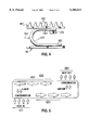
- FIG. 5 is illustrative of a basic Heat Pipe
- FIG. 6 is a graphical representation of example temperature cycles both external and internal to the packaging system of FIG. 1;
- FIG. 7 is an alternate embodiment of a Phase Change Module shown in perspective view, for use in the packaging system of FIG. 1 and is shown containing a honey comb heat distributing structure;
- FIG. 8 is a perspective view of the module of FIG. 7 and is shown containing a filamentary heat distributing structure.
- Electronic equipment which incorporate semi conductor components must provide ways of controlling the temperature the components in order to maintain component junction temperatures within the manufacturers specified range of typically -15° C. to +85° C.
- Another reliability requirement is to keep the components as well as substrate surfaces at a minimum of 7-10° C. above the external ambient temperature thereby minimizing humidity related problems from occuring. For example condensation causes moisture buildup on surfaces which for electronic equipment may cause electrolytic/galvanic corrosion.
- ion ladened moisture on and between signal tracks may also reduce reliability by causing leakage from one track to the other.
- T EXT worst case positive and worst case negative outdoor ambient temperature extreme
- An insulated outdoor equipment housing as is known in the art when subjected to the worst case positive or negative temperature extreme will undergo a delayed internal temperature swing (T INT ) and will generally peak at a temperature which is higher than the external ambient maximum as well as reach a minimum temperature which will be above the external ambient minimum. Differences between respective maximums and respective minimums is due largely to the heat produced by the actual equipment which is internal to the housing.
- T EXT an external ambient temperature peak
- the temperature internal (T INT ) to the housing can very often reach a peak of around +90° C. (shown in chain dot) which is well above the desired maximum internal ambient temperature of +50° C.
- T EXT external ambient
- the temperature internal to the housing can very often reach a minimum of around -30° C. (also shown in chain dot) which is lower than the desired minimum internal ambient temperature of -10° C.
- operating electronic equipment at these extremes will shorten component life span and generally the reliability of the equipment. It is also known that cycling operating temperatures even if the minimums and maximums are within the rated range, reduces the life span and reliability of equipment.
- Equipment enclosure 10 of the embodiment of FIG. 1 comprises a substantially sealed and insulated housing 12 which utilizes a combination of PCM and heat pipe technologies to provide efficient passive conductive cooling of electronic equipment.
- the housing 12 of the embodiment of FIG. 1 includes a diffusion passage for water vapor and a conventional access door (both of which are not shown).
- the diffusion passage ensures that the absolute humidity levels inside and outside of the housing are the same which helps to reduce condensation related problems.
- Components 14 are thermally and electrically conductively attached using known techniques to a substrate 16 (printed circuit board) to form a circuit pack 18.
- the substrate 16 of each circuit pack 18 is in turn thermally conductively attached to a facing surface of a major planar arm 22 of an ⁇ L ⁇ shaped support member 20 having high thermal conductive characteristics such as aluminum for example.
- the ⁇ L ⁇ shaped support member 20 can be better visualized with reference to FIG. 3 in which it is shown in perspective view.
- the major planar arm 22 of each ⁇ L ⁇ shaped support member 20 is of comparable surface area to the substrate 16 of a respective circuit pack 18.
- Electronic modules 30 in turn are thermally conductively attached in the following manner, to a highly thermally conductive heat spreading plate 32 which is disposed directly above the electronic modules 30.
- One surface of the small planar arm 24 of each ⁇ L ⁇ shaped support member 20 is thermally conductively attached using known techniques (thermal epoxies etc.) directly to a facing planar surface of the large rectangular heat spreading plate 32.
- a convection heat sink 40 forms at least a portion of the housing's 12 exterior wall directly above and spaced apart from the heat spreading plate 32. Fins 42 of the heat sink 40 are open to the ambient environment external to the housing 12.
- Thermal transistors in the form of a heat pipes 50 are disposed in the region between the heat sink 40 and the heat spreading plate 32 and are thermally conductively attached to an exteriorly facing surface of the heat spreading plate 32 and to the inwardly facing surface of the heat sink 40.
- Phase change material is encased within a highly thermally conductive framework to form circuit pack PCM modules 60. Each module 60 is sealed to the extent that it is able to contain the PCM during all stable phase states and transitions.
- PCM modules 60 are thermally conductively attached to the rear surface of the major planar arm 22, directly opposite respective circuit packs 18.
- Wall PCM modules 70 having different dimensions to the circuit pack PCM modules 60, are thermally conductively attached to an interior surface of each of the side walls 15 of the housing 12.
- FIG. 6 illustrates graphically an example temperature swing ⁇ T 3 internal (T INT ) of the housing resulting from a temperature swing external (T EXT ) of the housing. Shown in chain dot are the maximum and minimum peak ambient internal temperatures that the housing would be subjected to without any form of cooling in place.
- a housing in accordance with the invention can clip or limit the maximum peak internal temperature at the PCM threshold temperature (T PCM ) and as well limit the minimum peak internal temperature at the Heat Pipe threshold temperature (T HP ). Raising the Heat Pipe threshold temperature (T HP ) to a temperature above the -10° C. lower limit set by the commercial operating zone further reduces ⁇ T 3 therefore further increasing reliability.
- Heat pipe technology is used to efficiently conduct heat almost isothermally from inside of the housing 12 to a convection heat sink 40, external of the housing whenever the ambient internal temperature is above a predetermined first threshold temperature (T HP ) of for example 0° C.
- Phase Change Materials in the form of circuit pack PCM modules 60, 70, 80 further assist in controlling internal ambient temperature by effectively limiting or regulating the effects of short term localized thermal phenomena which might further increase internal temperatures above a second predetermined PCM threshold temperature (T PCM ).
- T PCM predetermined PCM threshold temperature
- heat pipes are designed, generally for average daily thermal conditions and not short term peak thermal phenomena. Short lived localized thermal loads or peaks (e.g.
- T PCM second predetermined temperature
- Wall PCM modules 70 similarly may prevent any further increase in internal temperature as a result of external solar temperature peaks.
- the internal minimum ambient temperature is regulated by effectively turning off the heat pipe 50 to thus provide a high thermal resistance between the interior of the housing 12 and the heat sink 40 to thereby preserve heat generated by the components 14 and effect heating of the housing 12.
- power in the form of heat dissipation from components 14, is thermally absorbed by the major arm 22 of respective ⁇ L ⁇ shaped support members 20 and through conduction is carried via each major arm 22 to the heat spreading plate 32.
- Each ⁇ L ⁇ shaped support member 20 operates in this manner to absorb and conduct heat away from respective circuit packs 18 and thermally carry it through conduction to the heat spreading plate 32.
- T HP a predetermined temperature
- the thermal transistor or in the embodiment the heat pipe 50 effectively turns on and conducts the heat energy from the heat spreading plate 32 out of the housing to heat sink 40 where fins 42 then vent this excess heat to the external ambient air.
- Utilizing a thermal transistor enables the housing 12 to contain or preserve internally generated heat from the components 14 for example during extreme cold periods such as in the winter or during a cold night portion of a daily temperature cycle.
- Preserving internally generated heat by turning off the conduction of heat to the heat sink 40 below a predetermined temperature provides two advantages. Firstly, it effectively limits any further downward trend of the internal temperature below a predetermined engineered value (e.g. 10° C.). Benefits gained by doing this result from increasing the temperature differential ( ⁇ T 2 FIG. 6) between ambient temperatures inside and outside the housing (humidity/condensation concerns) and of further reducing the temperature delta ⁇ T 1 between internal cycle minimums and maximums.
- a night sky can represent a radiant temperature in the range of -50° C. even though the ambient temperature external to the housing may only be in the range of -10° C.
- a housing for example having a heat sink facing the night sky and which is directly thermally coupled to the electronic equipment i.e.
- the thermal transistor (the heat pipe 50 in the embodiment) turns off under the same conditions and effectively then provides a very high thermal resistance in series with the heat sink or between the night sky and the equipment, thus reducing condensation concerns by preventing the interior ambient temperature from dropping below the exterior ambient temperature.
- Phase change materials exhibit characteristics which when used internally to an equipment housing will help to effectively cool the equipment by limiting and regulating the temperature within the housing to a predetermined value. It is known that Phase Change Materials through the latent heat of fusion are able to absorb significantly more heat during the change of state phase than in their stable states, i.e. either before or after the change of state phase. During the change of phase state, PCM absorbs heat energy with little or no increase in the temperature of the material itself. PCM can therefore be used to passively cool and regulate the temperature within a housing. The degree of cooling achievable is dependent upon the amount of PCM used, the type used and the placement of the PCM within the housing.
- phase change materials include not only those materials which go from a liquid phase to a solid phase a back to a liquid phase such as Paraffin Waxes do, but also includes those materials such as Neopentyl Glycol which go from a first solid phase to a second solid phase; with the difference between first and second solid phases being that each solid phase exhibits a different crystalline structure.
- these materials are phase change materials which change from one solid phase having one crystalline structure to a second solid phase having a different crystalline structure.
- the amount of PCM disposed within the housing can be engineered to effectively limit and regulate internal temperatures over the complete duration of the thermal spike.
- PCM e.g. paraffin wax
- the PCM changes phase it often does not do so uniformly and hence the desired temperature regulating characteristics during the phase change may not be realized.
- some of the available thermal absorption capacity of the PCM will not be realized if all of the material is not permitted to undergo the phase change (i.e. some of it does not melt).
- the PCM may be placed within a heat distributing structure constructed of any material having good thermal conducting properties. An example of such a structure is illustrated in FIG. 7.
- the honey-comb structure 84 fabricated from aluminum is encased within a framework 82 to contain the PCM and form a PCM module 80.
- the honey-comb heat distributing structure 84 more evenly subjects the whole of the contained PCM to local ambient temperatures which allows the PCM to change state at an even rate.
- Heat pipe technology in combination with Phase Change Materials can control temperature levels more efficiently within an equipment enclosure.
- Heat Pipes require no external power, have no moving parts, are sealed units, can be designed to operate over a very wide temperature range, and can be constructed to take on virtually any desired shape (tubes, flat plates etc.).
- Heat Pipes can transfer high heat loads while incurring only very small temperature drops (typically 1-2° C.) across the heat pipe.
- a heat pipe 100 comprises an evaporator 110, a vapor transport medium 120, a condenser 130, and a liquid return medium 140.
- the evaporator 110 portion of the Heat Pipe 100 is subjected to an undesired heat load where at a predetermined temperature, the liquid internal to the evaporator 110 vaporizes.
- the hot vapor is then allowed to flow along the vapor transport medium 120 towards the condenser 130 where it then condenses. While condensing, heat contained within the vapor is rejected and the liquid is returned back to the evaporator 110 by capillary forces within the liquid return medium 140 so that the process may be repeated.
- Some form of heat sink is disposed in thermal contact with the condenser 130 portion of the heat pipe 100 so as to conduct the undesired heat out of the housing to the external ambient air.
- Heat pipes can be designed to effectively turn off at a predetermined temperature by choosing a liquid which will essentially freeze at that temperature. Once the liquid freezes the evaporate/condense cycle ceases and the heat pipe effectively presents a very high thermal resistance between the heat sink and the inside of the housing.
- the Heat Pipe configuration just described generally is referred to as an Isothermalizer and can have multiple evaporators and condensers and may use either gravity or a wick as the liquid return medium.
- a preferred heat pipe 50 shown in FIG. 1 and more clearly in FIG. 4, referred to as a Variable Conductance Heat Pipe (VCHP) includes a reservoir 135 of non-condensable gas where the gas expands or contracts depending on temperature and hence pressure of the vapor from the Evaporator.
- VCHP Variable Conductance Heat Pipe
- vapor temperature in the Evaporator increases as a result of an increased thermal load which in turn causes the vapor pressure within the Evaporator to increase.
- a Variable Conductance Heat Pipe is best suited to transferring heat at near constant temperature in applications where variable thermal loads and environments are encountered.
- heat pipe 50 is used to switch on and off the cooling provided by one of the passive cooling devices, namely the heat sink 40.
- the heat pipe turns on the cooling provided by the heat sink 40 by providing a low thermal resistance between the heat spreading plate 32 and the heat sink 40 when the temperature of the heat spreading plate 32 is elevated above a predetermined threshold value (T HP ).
- T HP predetermined threshold value
- the heat pipe 50 effectively turns off the cooling provided by the heat sink 40 by providing a high thermal resistance between the heat spreading plate 32 and the heat sink 40 when the temperature of the heat spreading plate drops below the predetermined threshold value (T HP ).
- Other forms of thermal transistors or switches may be used to provide the switching on and off of cooling provided by the heat sink 40.
- Bi-metallic technology for example may be used to switch on and off cooling by using known expansion characteristics of dissimilar metals to provide an increase (switched on) or a decrease (switched off) in pressure between the heat spreading plate 32 and the heat sink 40.
- Thermostatic technology (such as is used in automobile thermostats) which utilizes the change in volume of a material through expansion properties of solids and liquids may also provide a passive mechanical thermal switch by increasing (switched on) or decreasing (switched off) the pressure between the heat spreading plate 32 and the heat sink 40.
- a convection heat sink 40 is used in the embodiment the invention is not limited to convection heat sinks.
- each ⁇ L ⁇ shaped support member 20 may not be capable of efficiently conducting this extra heat to the heat spreading plate 32 or as discussed earlier, the heat pipe 50 by design may not have the capacity to remove this extra heat or be able to respond quickly enough to prevent component temperatures from exceeding rated maximum temperatures.
- Circuit pack PCM modules 60 as illustrated in FIGS. 1, 2 are disposed adjacent the rear side of circuit packs 18 and are held in thermal contact with a back surface of the major planar arm 22. Increased equipment loads will invariably result in circuit packs 18 dissipating larger amounts of heat energy. This heat energy may be absorbed by the circuit pack PCM modules 60 hence permitting localized cooling of each circuit pack 18 during short term thermal peaks during those time intervals of peak time equipment loads.
- Cooling effectiveness using PCM may be enhanced or optimized by the relative placement of the PCM internal to the housing 12. As may be seen in FIG. 1 locating PCM modules 60 generally in close proximity to each circuit pack 18 effectively permits localized cooling of each circuit pack 18 during short term thermal peaks during those time intervals of peak time equipment loads. Cooling effectiveness may be further enhanced by having PCM modules 60 thermally conductively attached to respective major planar arms 22 which are in turn thermally conductively attached to respective substrates 16 of each circuit pack 18. Placement of PCM modules 70 on interior walls 15 of the housing 12 generally will aid in the cooling of the internal ambient temperature should it reach the particular PCM threshold temperature.
- PCM modules for use adjacent circuit packs 18 may contain different PCM from PCM modules positioned elsewhere in the housing (walls for example) to effectively provide staggered turn on thresholds.
- One or more walls 15 of the housing 12 may also be used depending on the degree of cooling required. Certain applications may require or benefit from PCM modules being disposed in direct thermal contact with the heat spreading plate 32, alongside the heat pipe 50.
- Other alternatives are for more than one type of PCM to be used within a single PCM module in order to act as temperature buffers at various times of the year.
- Equipment having shelving arrangements which utilize one or more conventional printed circuit board receiving stations may also benefit by having PCM disposed adjacent to respective receiving stations for cooling respective circuit boards when in use.
- phase change threshold temperature (T PCM ) for the PCM was chosen to be in the range of 35-60° C. which is higher than the turn on temperature (T HP ) for the heat pipe of 0° C. (i.e. the heat pipe effectively turns on before the PCM).
- T HP turn on temperature
- the PCM temperature thresholds could be chosen to be the same as or lower than the heat pipe turn on temperature.
- PCM modules disposed on one or more exterior walls can be used to advantageously absorb and store solar heat energy during one phase transition and to later release heat energy during the a second phase transition.
- liquid metals such as Indalloy 117, Indalloy 136, and Indalloy 19 which may be used in PCM modules and which generally have higher densities for the same or similar latent heat of fusion of the more traditional phase change materials.
- the liquid metals listed above are alloys containing; Indalloy 117 (44.7% Bi, 22.6% Pb, 19.1% In, 8.3% Sn, and 5.3% Cd), Indalloy 136 (49% Bi, 21% In, 18% Pb, and 12% Sn), and Indalloy 19 (51% In, 32.5% Bi, 16.5 Sn).
Abstract
Description
Claims (15)
Priority Applications (1)
| Application Number | Priority Date | Filing Date | Title |
|---|---|---|---|
| US08/725,778 US6104611A (en) | 1995-10-05 | 1996-10-04 | Packaging system for thermally controlling the temperature of electronic equipment |
Applications Claiming Priority (2)
| Application Number | Priority Date | Filing Date | Title |
|---|---|---|---|
| US481295P | 1995-10-05 | 1995-10-05 | |
| US08/725,778 US6104611A (en) | 1995-10-05 | 1996-10-04 | Packaging system for thermally controlling the temperature of electronic equipment |
Publications (1)
| Publication Number | Publication Date |
|---|---|
| US6104611A true US6104611A (en) | 2000-08-15 |
Family
ID=26673512
Family Applications (1)
| Application Number | Title | Priority Date | Filing Date |
|---|---|---|---|
| US08/725,778 Expired - Lifetime US6104611A (en) | 1995-10-05 | 1996-10-04 | Packaging system for thermally controlling the temperature of electronic equipment |
Country Status (1)
| Country | Link |
|---|---|
| US (1) | US6104611A (en) |
Cited By (170)
| Publication number | Priority date | Publication date | Assignee | Title |
|---|---|---|---|---|
| US6181558B1 (en) * | 1999-08-24 | 2001-01-30 | Cairns Advanced Tech. Inc. | Heat absorber and combination electrical apparatus producing heat and heat absorber |
| US6310772B1 (en) * | 1999-09-02 | 2001-10-30 | Special Product Company | Enclosure for telecommunications equipment |
| US6360813B1 (en) * | 1999-05-20 | 2002-03-26 | Ts Heatronics Co., Ltd. | Electronic components cooling apparatus |
| US6388882B1 (en) * | 2001-07-19 | 2002-05-14 | Thermal Corp. | Integrated thermal architecture for thermal management of high power electronics |
| US6392883B1 (en) * | 2000-06-30 | 2002-05-21 | Intel Corporation | Heat exchanger having phase change material for a portable computing device |
| US6394175B1 (en) * | 2000-01-13 | 2002-05-28 | Lucent Technologies Inc. | Top mounted cooling device using heat pipes |
| US6404637B2 (en) | 2000-02-14 | 2002-06-11 | Special Product Company | Concentrical slot telecommunications equipment enclosure |
| US6421240B1 (en) * | 2001-04-30 | 2002-07-16 | Hewlett-Packard Company | Cooling arrangement for high performance electronic components |
| US6430044B2 (en) | 2000-02-10 | 2002-08-06 | Special Product Company | Telecommunications enclosure with individual, separated card holders |
| US6507494B1 (en) | 2000-07-27 | 2003-01-14 | Adc Telecommunications, Inc. | Electronic equipment enclosure |
| US6510223B2 (en) | 1997-11-06 | 2003-01-21 | Anacapa Technology, Inc. | Local loop telecommunication repeater housings employing thermal collection, transfer and distribution via solid thermal conduction |
| US6514095B1 (en) | 2000-07-27 | 2003-02-04 | Special Product Company | Cable interface for electronic equipment enclosure |
| US20030025966A1 (en) * | 2001-08-03 | 2003-02-06 | Ross Halgren | OSP hardened WDM network |
| US6542368B2 (en) * | 2000-10-05 | 2003-04-01 | Nec Corporation | Heat sink and power source unit employing the same |
| US6564861B1 (en) * | 1999-09-03 | 2003-05-20 | Fujitsu Limited | Cooling unit |
| US6574082B2 (en) * | 2001-10-09 | 2003-06-03 | Ericsson Inc. | Methods and systems for operating temperature controls for electronic equipment |
| EP1322057A1 (en) * | 2001-12-21 | 2003-06-25 | Redfern Broadband Networks Inc. | WDM add/drop multiplexer module |
| US20030128512A1 (en) * | 2001-12-21 | 2003-07-10 | Owens Mark J. | Improved vdm and/drop multiplexer module |
| US6598404B2 (en) * | 2000-04-20 | 2003-07-29 | Oxford Magnet Technology Limited | Cooling apparatus |
| US20030158704A1 (en) * | 2000-11-27 | 2003-08-21 | Phil Triginai | Apparatus and method for diagnosing performance of air-conditioning systems |
| US6618250B2 (en) | 2001-08-30 | 2003-09-09 | Ericsson Inc. | Modular electronics enclosure |
| US6621707B2 (en) * | 1998-08-11 | 2003-09-16 | Fujitsu Limited | Liquid-cooled electronic apparatus |
| US6625017B1 (en) | 2001-02-12 | 2003-09-23 | Special Products Company | Telecommunications enclosure with individual, separated card holders |
| US6628521B2 (en) | 2000-11-06 | 2003-09-30 | Adc Telecommunications, Inc. | Mechanical housing |
| US20030218867A1 (en) * | 2002-05-24 | 2003-11-27 | Adc Dsl Systems, Inc. | Housings for circuit cards |
| US6668819B1 (en) | 2001-12-31 | 2003-12-30 | Ralph Remsburg | Method and apparatus for temperature control of an enclosure |
| US6675887B2 (en) | 2002-03-26 | 2004-01-13 | Thermal Corp. | Multiple temperature sensitive devices using two heat pipes |
| US6691766B1 (en) * | 2000-09-15 | 2004-02-17 | Lucent Technologies Inc. | Cabinet cooling with heat pipe |
| WO2004019065A1 (en) * | 2002-08-20 | 2004-03-04 | Vaisala Oyj | Sond for atmospheric measurements |
| US20040085733A1 (en) * | 2002-10-30 | 2004-05-06 | Charles Industries, Ltd. | Heat pipe cooled electronics enclosure |
| US20040085728A1 (en) * | 2002-11-05 | 2004-05-06 | Barth Michael K. | Methods and systems of heat transfer for electronic enclosures |
| US20040132503A1 (en) * | 2003-01-03 | 2004-07-08 | Chia-Pin Chiu | Thermal management for telecommunication devices |
| WO2004109798A1 (en) * | 2003-05-22 | 2004-12-16 | Siemens Aktiengesellschaft | Method and assembly for thermally protecting electronic units in an electronic device |
| US6865085B1 (en) | 2003-09-26 | 2005-03-08 | Adc Dsl Systems, Inc. | Heat dissipation for electronic enclosures |
| US20050099776A1 (en) * | 2003-11-12 | 2005-05-12 | Xue Liang A. | Passive thermal switch |
| US6894907B2 (en) | 2001-07-31 | 2005-05-17 | Adc Telecommunications, Inc. | Clamping case |
| US6897377B2 (en) | 2001-07-31 | 2005-05-24 | Adc Telecommunications, Inc. | Clamping receptacle |
| EP1560479A2 (en) * | 2004-01-29 | 2005-08-03 | Fujitsu Limited | Cabinet having heat radiation function and heat radiation member |
| US6940014B1 (en) | 2000-07-27 | 2005-09-06 | Special Product Company | Modular electronic equipment enclosure comprising sealed cable interface module |
| US20050207120A1 (en) * | 2004-03-16 | 2005-09-22 | Industrial Technology Research Institute | Thermal module with heat reservoir and method of applying the same on electronic products |
| US20050231915A1 (en) * | 2004-04-15 | 2005-10-20 | Hendry Mechanical Works | Thermally insulated cabinet and method for inhibiting heat transfer |
| US20050280987A1 (en) * | 2004-06-07 | 2005-12-22 | Kwitek Benjamin J | Phase change materials as a heat sink for computers |
| US6991351B1 (en) * | 2003-12-15 | 2006-01-31 | Twr Lighting, Inc. | Illumination system |
| US20060102353A1 (en) * | 2004-11-12 | 2006-05-18 | Halliburton Energy Services, Inc. | Thermal component temperature management system and method |
| US20060146496A1 (en) * | 2005-01-06 | 2006-07-06 | The Boeing Company | Cooling apparatus, system, and associated method |
| US20070115635A1 (en) * | 2005-11-18 | 2007-05-24 | Low Andrew G | Passive cooling for fiber to the premise (FTTP) electronics |
| US20070146990A1 (en) * | 2005-12-23 | 2007-06-28 | Hon Hai Precision Industry Co., Ltd. | Heat dissipating assembly |
| US20070187069A1 (en) * | 2004-07-20 | 2007-08-16 | Furukawa-Sky Aluminum Corp. | Heat Pipe heat sink |
| US20070195503A1 (en) * | 2006-02-21 | 2007-08-23 | 3Com Corporation | Apparatus for dissipating heat from electronic components in an enclosed housing |
| US20080034774A1 (en) * | 2006-07-19 | 2008-02-14 | Brower Keith R | Active thermal insulation system utilizing phase change material and a cool air source |
| US20080049949A1 (en) * | 2006-08-18 | 2008-02-28 | Snider Chris R | Lightweight audio system for automotive applications and method |
| US20080055864A1 (en) * | 2006-08-30 | 2008-03-06 | Siemens Aktiengesellschaft | Module for an automation device |
| US20080084666A1 (en) * | 2006-10-06 | 2008-04-10 | Honeywell International, Inc. | Liquid cooled electronic chassis having a plurality of phase change material reservoirs |
| US20080087406A1 (en) * | 2006-10-13 | 2008-04-17 | The Boeing Company | Cooling system and associated method for planar pulsating heat pipe |
| US20080115911A1 (en) * | 2006-11-22 | 2008-05-22 | Tyco Electronics Corporation | Heat dissipation system for solarlok photovoltaic interconnection system |
| US20080122724A1 (en) * | 2006-04-14 | 2008-05-29 | Murata Manufacturing Co., Ltd. | Antenna |
| US20080184336A1 (en) * | 2007-01-29 | 2008-07-31 | Sekhar Sarukkai | Policy resolution in an entitlement management system |
| US7450382B1 (en) | 2007-05-15 | 2008-11-11 | Adc Telecommunications, Inc. | Apparatus for enclosing electronic components |
| US20080278915A1 (en) * | 2007-05-10 | 2008-11-13 | Adc Telecommunications, Inc. | Chassis mounted heat sink system |
| US20080285229A1 (en) * | 2007-05-15 | 2008-11-20 | Hayato Watanabe | Heat dissipating member, heat dissipating mechanism, and information processing apparatus |
| US7457118B1 (en) * | 2003-12-19 | 2008-11-25 | Emc Corporation | Method and apparatus for dispersing heat from high-power electronic devices |
| US20080291627A1 (en) * | 2007-05-23 | 2008-11-27 | Adc Telecommunications, Inc. | Apparatus for enclosing electronic components used in telecommunication systems |
| US20090009007A1 (en) * | 2006-04-26 | 2009-01-08 | Murata Manufacturing Co., Ltd. | Product including power supply circuit board |
| US20090021908A1 (en) * | 2007-07-18 | 2009-01-22 | Chandrakant Patel | System and method for cooling an electronic device |
| US20090052360A1 (en) * | 2006-05-30 | 2009-02-26 | Murata Manufacturing Co., Ltd. | Information terminal device |
| US20090066592A1 (en) * | 2006-06-12 | 2009-03-12 | Murata Manufacturing Co., Ltd. | System for inspecting electromagnetic coupling modules and radio ic devices and method for manufacturing electromagnetic coupling modules and radio ic devices using the system |
| US20090080296A1 (en) * | 2006-06-30 | 2009-03-26 | Murata Manufacturing Co., Ltd. | Optical disc |
| US20090109102A1 (en) * | 2006-07-11 | 2009-04-30 | Murata Manufacturing Co., Ltd. | Antenna and radio ic device |
| US20090109623A1 (en) * | 2007-10-31 | 2009-04-30 | Forcecon Technology Co., Ltd. | Heat-radiating module with composite phase-change heat-radiating efficiency |
| US20090146821A1 (en) * | 2007-07-09 | 2009-06-11 | Murata Manufacturing Co., Ltd. | Wireless ic device |
| US20090154102A1 (en) * | 2007-12-12 | 2009-06-18 | Fu Zhun Precision Industry (Shen Zhen) Co., Ltd. | Heat dissipation device |
| US20090179810A1 (en) * | 2006-10-27 | 2009-07-16 | Murata Manufacturing Co., Ltd. | Article having electromagnetic coupling module attached thereto |
| US20090201156A1 (en) * | 2007-06-27 | 2009-08-13 | Murata Manufacturing Co., Ltd. | Wireless ic device |
| US20090219726A1 (en) * | 2008-03-02 | 2009-09-03 | Matt Weaver | Thermal storage system using phase change materials in led lamps |
| US20090232033A1 (en) * | 2007-02-07 | 2009-09-17 | Patrick Isakanian | Hybrid frequency compensation network |
| US20090262041A1 (en) * | 2007-07-18 | 2009-10-22 | Murata Manufacturing Co., Ltd. | Wireless ic device |
| US20090278760A1 (en) * | 2007-04-26 | 2009-11-12 | Murata Manufacturing Co., Ltd. | Wireless ic device |
| US20090302121A1 (en) * | 2007-04-09 | 2009-12-10 | Murata Manufacturing Co., Ltd. | Wireless ic device |
| US20100027220A1 (en) * | 2008-08-04 | 2010-02-04 | Clustered Systems Company | Contact cooled electronic enclosure |
| US20100038053A1 (en) * | 2008-08-15 | 2010-02-18 | Maxik Fredric S | Sustainable endothermic heat stripping method and apparatus |
| US20100046175A1 (en) * | 2008-06-18 | 2010-02-25 | Lockheed Martin Corporation | Electronics module, enclosure assembly housing same, and related systems and methods |
| US20100046177A1 (en) * | 2008-06-18 | 2010-02-25 | Lockheed Martin Corporation | Enclosure assembly housing at least one electronic board assembly and systems using same |
| US20100063647A1 (en) * | 2008-09-11 | 2010-03-11 | Joseph Yeh | Outdoor enclosure cooling system operating at off-peak hours |
| US20100061053A1 (en) * | 2008-09-08 | 2010-03-11 | Intergraph Technologies Company | Ruggedized Computer Capable of Operating in High-Temperature Environments |
| US20100103058A1 (en) * | 2007-07-18 | 2010-04-29 | Murata Manufacturing Co., Ltd. | Radio ic device |
| US7762472B2 (en) | 2007-07-04 | 2010-07-27 | Murata Manufacturing Co., Ltd | Wireless IC device |
| US20100208428A1 (en) * | 2009-02-13 | 2010-08-19 | Asia Vital Components Co., Ltd. | Communication chassis heat dissipation structure |
| US20100246128A1 (en) * | 2009-03-31 | 2010-09-30 | Domhnaill Hernon | Circuit Pack Cooling Solution |
| US20100264790A1 (en) * | 2009-04-21 | 2010-10-21 | Hong Fu Jin Precision Industry (Shenzhen) Co., Ltd. | Computer enclosure |
| US20100302013A1 (en) * | 2008-03-03 | 2010-12-02 | Murata Manufacturing Co., Ltd. | Radio frequency ic device and radio communication system |
| US20110038120A1 (en) * | 2001-04-24 | 2011-02-17 | Apple Inc. | Heat dissipation in computing device |
| US20110081617A1 (en) * | 2009-10-05 | 2011-04-07 | Chia-Fang Lin | Integrated lithography equipment and lithography process thereof |
| US20110083826A1 (en) * | 2009-10-13 | 2011-04-14 | Auston Robert Matta | Thermally-controlled packaging device and method of making |
| US7931206B2 (en) | 2007-05-10 | 2011-04-26 | Murata Manufacturing Co., Ltd. | Wireless IC device |
| US20110110041A1 (en) * | 2009-11-06 | 2011-05-12 | Shwin-Chung Wong | Heat disspation structure of electronic apparatus |
| US7964129B1 (en) * | 1998-06-11 | 2011-06-21 | Malcolm Barry James | Temperature control method and apparatus |
| US20110168727A1 (en) * | 2007-05-04 | 2011-07-14 | Entropy Solutions, Inc. | Package Having Phase Change Materials and Method of Use in Transport of Temperature Sensitive Payload |
| US7997501B2 (en) | 2007-07-17 | 2011-08-16 | Murata Manufacturing Co., Ltd. | Wireless IC device and electronic apparatus |
| US8031124B2 (en) | 2007-01-26 | 2011-10-04 | Murata Manufacturing Co., Ltd. | Container with electromagnetic coupling module |
| US20120106070A1 (en) * | 2010-11-02 | 2012-05-03 | Trevor Landon | Field serviceable cpu module |
| CN102573397A (en) * | 2010-12-23 | 2012-07-11 | 山特电子(深圳)有限公司 | Heat transmission device as well as manufacturing and assembling method and equipment assembly of heat transmission device |
| US20120176223A1 (en) * | 2009-09-28 | 2012-07-12 | Murata Manufacturing Co., Ltd. | Wireless ic device and method of detecting environmental state using the device |
| US8228075B2 (en) | 2006-08-24 | 2012-07-24 | Murata Manufacturing Co., Ltd. | Test system for radio frequency IC devices and method of manufacturing radio frequency IC devices using the same |
| US8299968B2 (en) | 2007-02-06 | 2012-10-30 | Murata Manufacturing Co., Ltd. | Packaging material with electromagnetic coupling module |
| US8299929B2 (en) | 2006-09-26 | 2012-10-30 | Murata Manufacturing Co., Ltd. | Inductively coupled module and item with inductively coupled module |
| US8336786B2 (en) | 2010-03-12 | 2012-12-25 | Murata Manufacturing Co., Ltd. | Wireless communication device and metal article |
| US8342416B2 (en) | 2009-01-09 | 2013-01-01 | Murata Manufacturing Co., Ltd. | Wireless IC device, wireless IC module and method of manufacturing wireless IC module |
| US8400365B2 (en) | 2009-11-20 | 2013-03-19 | Murata Manufacturing Co., Ltd. | Antenna device and mobile communication terminal |
| US8424769B2 (en) | 2010-07-08 | 2013-04-23 | Murata Manufacturing Co., Ltd. | Antenna and RFID device |
| US20130168058A1 (en) * | 2011-03-14 | 2013-07-04 | Dell Products, Lp | System, Apparatus and Method for Cooling Electronic Components |
| US20130213075A1 (en) * | 2012-02-21 | 2013-08-22 | Thermal Corp. | Electronics cabinet and rack cooling system and method |
| US8546927B2 (en) | 2010-09-03 | 2013-10-01 | Murata Manufacturing Co., Ltd. | RFIC chip mounting structure |
| GB2501250A (en) * | 2012-04-16 | 2013-10-23 | Creactive Design Engineering Ltd | Metal cabinet for electrical apparatus with containers of phase change material for temperature control |
| WO2013158987A1 (en) * | 2012-04-19 | 2013-10-24 | Lee Cooper G | Backplane design for miniature configurable communications data center |
| US8583043B2 (en) | 2009-01-16 | 2013-11-12 | Murata Manufacturing Co., Ltd. | High-frequency device and wireless IC device |
| US8602310B2 (en) | 2010-03-03 | 2013-12-10 | Murata Manufacturing Co., Ltd. | Radio communication device and radio communication terminal |
| US8632227B2 (en) | 2008-03-02 | 2014-01-21 | Lumenetix, Inc. | Heat removal system and method for light emitting diode lighting apparatus |
| US8668151B2 (en) | 2008-03-26 | 2014-03-11 | Murata Manufacturing Co., Ltd. | Wireless IC device |
| EP2333474A3 (en) * | 2009-12-11 | 2014-03-19 | Vysoké Ucení Technické V Brne | Heat accumulating module with PCM, module's assembly and double heat accumulating wall |
| US8760886B2 (en) | 2006-08-18 | 2014-06-24 | Delphi Technologies, Inc. | Lightweight audio system for automotive applications and method |
| US8783894B2 (en) | 2010-02-12 | 2014-07-22 | Lumenetix, Inc. | LED lamp assembly with thermal management system |
| US20140217870A1 (en) * | 2013-02-01 | 2014-08-07 | Emerson Network Power - Embedded Computing, Inc. | Method and device to provide uniform cooling in rugged environments |
| US8810456B2 (en) | 2009-06-19 | 2014-08-19 | Murata Manufacturing Co., Ltd. | Wireless IC device and coupling method for power feeding circuit and radiation plate |
| US8814056B2 (en) | 2011-07-19 | 2014-08-26 | Murata Manufacturing Co., Ltd. | Antenna device, RFID tag, and communication terminal apparatus |
| US20140247857A1 (en) * | 2013-03-01 | 2014-09-04 | Futurewei Technologies, Inc. | System and Method for Measuring Thermal Reliability of Multi-Chip Modules |
| US8876010B2 (en) | 2009-04-14 | 2014-11-04 | Murata Manufacturing Co., Ltd | Wireless IC device component and wireless IC device |
| US8915448B2 (en) | 2007-12-26 | 2014-12-23 | Murata Manufacturing Co., Ltd. | Antenna device and radio frequency IC device |
| US8917211B2 (en) | 2008-11-17 | 2014-12-23 | Murata Manufacturing Co., Ltd. | Antenna and wireless IC device |
| WO2015016975A1 (en) * | 2013-07-30 | 2015-02-05 | Johnson Controls Technology Company | Battery module with phase change material |
| US8994605B2 (en) | 2009-10-02 | 2015-03-31 | Murata Manufacturing Co., Ltd. | Wireless IC device and electromagnetic coupling module |
| US9077067B2 (en) | 2008-07-04 | 2015-07-07 | Murata Manufacturing Co., Ltd. | Radio IC device |
| US9101082B1 (en) * | 2010-05-03 | 2015-08-04 | Sunpower Corporation | Junction box thermal management |
| US9136202B2 (en) | 2012-04-17 | 2015-09-15 | Qualcomm Incorporated | Enhanced package thermal management using external and internal capacitive thermal material |
| US9151531B2 (en) | 2013-05-16 | 2015-10-06 | Sandy Wengreen | Storage systems and methods for medicines |
| US9237685B2 (en) | 2006-08-18 | 2016-01-12 | Delphi Technologies, Inc. | Lightweight audio system for automotive applications and method |
| WO2016030005A1 (en) * | 2014-08-28 | 2016-03-03 | Diehl Aerospace Gmbh | Modular assembly |
| US20160109911A1 (en) * | 2014-10-15 | 2016-04-21 | Futurewei Technologies, Inc. | Support frame with integrated phase change material for thermal management |
| WO2016099785A1 (en) * | 2014-12-17 | 2016-06-23 | Google Inc. | Battery pack with variable-conductance heat pipe (vchp) cooling |
| US9378452B2 (en) | 2011-05-16 | 2016-06-28 | Murata Manufacturing Co., Ltd. | Radio IC device |
| US20160295744A1 (en) * | 2013-11-12 | 2016-10-06 | Molex Incorporated | Thermally configured connector system |
| US9558384B2 (en) | 2010-07-28 | 2017-01-31 | Murata Manufacturing Co., Ltd. | Antenna apparatus and communication terminal instrument |
| US20170112018A1 (en) * | 2015-10-20 | 2017-04-20 | General Electric Company | Heat transfer chassis and method for forming the same |
| CN106714518A (en) * | 2017-01-04 | 2017-05-24 | 北京中安科创科技发展有限公司 | Wide-temperature heat control device |
| US9692128B2 (en) | 2012-02-24 | 2017-06-27 | Murata Manufacturing Co., Ltd. | Antenna device and wireless communication device |
| US9707156B2 (en) | 2013-05-16 | 2017-07-18 | Sandy Wengreen | Storage systems and methods for medicines |
| US9761923B2 (en) | 2011-01-05 | 2017-09-12 | Murata Manufacturing Co., Ltd. | Wireless communication device |
| US20170290205A1 (en) * | 2016-04-04 | 2017-10-05 | Hamilton Sundstrand Corporation | Immersion cooling systems and methods |
| US9791304B2 (en) | 2015-10-21 | 2017-10-17 | Honeywell International Inc. | Air data probe heater utilizing low melting point metal |
| USD804807S1 (en) | 2016-09-22 | 2017-12-12 | Sandy Wengreen | Insulated container |
| US9877894B2 (en) | 2013-05-16 | 2018-01-30 | Sandy Wengreen | Storage systems and methods for medicines |
| US20180045585A1 (en) * | 2016-08-12 | 2018-02-15 | Thermodata Corporation | Sensor Module and Process for Producing Same |
| US9913777B2 (en) | 2013-05-16 | 2018-03-13 | Sandy Wengreen | Storage systems and methods for medicines |
| US10013650B2 (en) | 2010-03-03 | 2018-07-03 | Murata Manufacturing Co., Ltd. | Wireless communication module and wireless communication device |
| US20180201388A1 (en) * | 2017-01-19 | 2018-07-19 | Graduate School At Shenzhen, Tsinghua University | Heat managing and dispersing structure and unmanned aerial vehicle using the same |
| EP1894285B1 (en) * | 2005-06-07 | 2018-08-29 | Underwater Kinetics | A flashlight with improved battery life |
| US10070553B2 (en) | 2016-02-24 | 2018-09-04 | Ciena Corporation | Connector replacement methods in a network element chassis |
| US20180290044A1 (en) * | 2016-08-11 | 2018-10-11 | Boe Technology Group Co., Ltd. | Protective gear and operating control method thereof |
| US10183753B2 (en) * | 2015-07-28 | 2019-01-22 | Thales | Avionic equipment heating |
| US10235544B2 (en) | 2012-04-13 | 2019-03-19 | Murata Manufacturing Co., Ltd. | Inspection method and inspection device for RFID tag |
| AU2014201023B2 (en) * | 2014-02-26 | 2019-07-18 | Creactive Design (Engineering) Limited | Cabinet for electrical apparatus with containers of phase change material for temperature control |
| US10588820B2 (en) | 2013-05-16 | 2020-03-17 | Sandy Wengreen | Storage systems and methods for medicines |
| US10722427B2 (en) | 2018-03-29 | 2020-07-28 | Simon Charles Cantor | Hermetically sealable case for medical device and medicine |
| US10798848B2 (en) | 2016-04-14 | 2020-10-06 | Microsoft Technology Licensing, Llc | Passive thermal management system with phase change material |
| US20200377279A1 (en) * | 2019-06-03 | 2020-12-03 | Sonoco Development, Inc. | Heat Pipe Cooled Pallet Shipper |
| US10996083B2 (en) * | 2018-02-15 | 2021-05-04 | Robert Bosch Gmbh | Sensor system for attaching a sensor set-up to a vehicle |
| US11432434B2 (en) | 2020-12-07 | 2022-08-30 | Ciena Corporation | Apparatus and method for modifying airflow of a network element |
| US20220363144A1 (en) * | 2021-05-17 | 2022-11-17 | Ford Global Technologies, Llc | Traction battery pack thermal management assembly |
| US11516558B2 (en) | 2020-09-10 | 2022-11-29 | Ciena Corporation | Angled faceplates for a network element |
| US11617285B2 (en) | 2021-03-19 | 2023-03-28 | Ciena Corporation | Hardened, telecommunications clamshell platform with heat load sharing between both halves of the platform |
| CN115996330A (en) * | 2023-03-23 | 2023-04-21 | 深圳市振兴光通信股份有限公司 | Industrial grade router |
Citations (7)
| Publication number | Priority date | Publication date | Assignee | Title |
|---|---|---|---|---|
| US3851221A (en) * | 1972-11-30 | 1974-11-26 | P Beaulieu | Integrated circuit package |
| US4306613A (en) * | 1980-03-10 | 1981-12-22 | Christopher Nicholas S | Passive cooling system |
| US5076351A (en) * | 1989-07-19 | 1991-12-31 | Showa Aluminum Corporation | Heat pipe |
| US5315154A (en) * | 1993-05-14 | 1994-05-24 | Hughes Aircraft Company | Electronic assembly including heat absorbing material for limiting temperature through isothermal solid-solid phase transition |
| US5325913A (en) * | 1993-06-25 | 1994-07-05 | The United States Of America As Represented By The Secretary Of The Navy | Module cooling system |
| US5396404A (en) * | 1993-09-20 | 1995-03-07 | Delco Electronics Corp. | Heat sinking assembly for electrical components |
| US5455458A (en) * | 1993-08-09 | 1995-10-03 | Hughes Aircraft Company | Phase change cooling of semiconductor power modules |
-
1996
- 1996-10-04 US US08/725,778 patent/US6104611A/en not_active Expired - Lifetime
Patent Citations (7)
| Publication number | Priority date | Publication date | Assignee | Title |
|---|---|---|---|---|
| US3851221A (en) * | 1972-11-30 | 1974-11-26 | P Beaulieu | Integrated circuit package |
| US4306613A (en) * | 1980-03-10 | 1981-12-22 | Christopher Nicholas S | Passive cooling system |
| US5076351A (en) * | 1989-07-19 | 1991-12-31 | Showa Aluminum Corporation | Heat pipe |
| US5315154A (en) * | 1993-05-14 | 1994-05-24 | Hughes Aircraft Company | Electronic assembly including heat absorbing material for limiting temperature through isothermal solid-solid phase transition |
| US5325913A (en) * | 1993-06-25 | 1994-07-05 | The United States Of America As Represented By The Secretary Of The Navy | Module cooling system |
| US5455458A (en) * | 1993-08-09 | 1995-10-03 | Hughes Aircraft Company | Phase change cooling of semiconductor power modules |
| US5396404A (en) * | 1993-09-20 | 1995-03-07 | Delco Electronics Corp. | Heat sinking assembly for electrical components |
Non-Patent Citations (1)
| Title |
|---|
| Counter Flow Cooling, Chu, IBM Tech Discl Bull vol. 8 No. 11 Apr. 1966, pp. 1692. * |
Cited By (293)
| Publication number | Priority date | Publication date | Assignee | Title |
|---|---|---|---|---|
| US6510223B2 (en) | 1997-11-06 | 2003-01-21 | Anacapa Technology, Inc. | Local loop telecommunication repeater housings employing thermal collection, transfer and distribution via solid thermal conduction |
| US6798878B2 (en) | 1997-11-06 | 2004-09-28 | Anacapa Technology, Inc. | Local loop telecommunication repeater housing having mounting slots enabling replaceable repeater and voltage protector assemblies |
| US20110232856A1 (en) * | 1998-06-11 | 2011-09-29 | Malcolm Barry James | Temperature control method and apparatus |
| US7964129B1 (en) * | 1998-06-11 | 2011-06-21 | Malcolm Barry James | Temperature control method and apparatus |
| US6621707B2 (en) * | 1998-08-11 | 2003-09-16 | Fujitsu Limited | Liquid-cooled electronic apparatus |
| US6360813B1 (en) * | 1999-05-20 | 2002-03-26 | Ts Heatronics Co., Ltd. | Electronic components cooling apparatus |
| US6181558B1 (en) * | 1999-08-24 | 2001-01-30 | Cairns Advanced Tech. Inc. | Heat absorber and combination electrical apparatus producing heat and heat absorber |
| US6310772B1 (en) * | 1999-09-02 | 2001-10-30 | Special Product Company | Enclosure for telecommunications equipment |
| US6564861B1 (en) * | 1999-09-03 | 2003-05-20 | Fujitsu Limited | Cooling unit |
| US7337829B2 (en) | 1999-09-03 | 2008-03-04 | Fujitsu Limited | Cooling unit |
| US7828047B2 (en) | 1999-09-03 | 2010-11-09 | Fujitsu Limited | Cooling unit |
| US20080236797A1 (en) * | 1999-09-03 | 2008-10-02 | Fujitsu Limited | Cooling unit |
| US6394175B1 (en) * | 2000-01-13 | 2002-05-28 | Lucent Technologies Inc. | Top mounted cooling device using heat pipes |
| US6430044B2 (en) | 2000-02-10 | 2002-08-06 | Special Product Company | Telecommunications enclosure with individual, separated card holders |
| US6611426B2 (en) | 2000-02-10 | 2003-08-26 | Special Products Company | Telecommunications enclosure with individual, separated card holders |
| US6404637B2 (en) | 2000-02-14 | 2002-06-11 | Special Product Company | Concentrical slot telecommunications equipment enclosure |
| US6598404B2 (en) * | 2000-04-20 | 2003-07-29 | Oxford Magnet Technology Limited | Cooling apparatus |
| US6392883B1 (en) * | 2000-06-30 | 2002-05-21 | Intel Corporation | Heat exchanger having phase change material for a portable computing device |
| US6507494B1 (en) | 2000-07-27 | 2003-01-14 | Adc Telecommunications, Inc. | Electronic equipment enclosure |
| US6940014B1 (en) | 2000-07-27 | 2005-09-06 | Special Product Company | Modular electronic equipment enclosure comprising sealed cable interface module |
| US6514095B1 (en) | 2000-07-27 | 2003-02-04 | Special Product Company | Cable interface for electronic equipment enclosure |
| US6691766B1 (en) * | 2000-09-15 | 2004-02-17 | Lucent Technologies Inc. | Cabinet cooling with heat pipe |
| US6542368B2 (en) * | 2000-10-05 | 2003-04-01 | Nec Corporation | Heat sink and power source unit employing the same |
| US6628521B2 (en) | 2000-11-06 | 2003-09-30 | Adc Telecommunications, Inc. | Mechanical housing |
| US7075789B2 (en) | 2000-11-06 | 2006-07-11 | Adc Telecommunications, Inc. | Mechanical housing |
| US20080239674A1 (en) * | 2000-11-06 | 2008-10-02 | Adc Dsl Systems, Inc. | Mechanical housing |
| US20040163552A1 (en) * | 2000-11-06 | 2004-08-26 | Adc Telecommunications, Inc. | Mechanical housing |
| US7633757B2 (en) * | 2000-11-06 | 2009-12-15 | Adc Dsl Systems, Inc. | Mechanical housing |
| US7146290B2 (en) * | 2000-11-27 | 2006-12-05 | Uview Ultraviolet Systems, Inc. | Apparatus and method for diagnosing performance of air-conditioning systems |
| US20030158704A1 (en) * | 2000-11-27 | 2003-08-21 | Phil Triginai | Apparatus and method for diagnosing performance of air-conditioning systems |
| US6625017B1 (en) | 2001-02-12 | 2003-09-23 | Special Products Company | Telecommunications enclosure with individual, separated card holders |
| US9116674B2 (en) | 2001-04-24 | 2015-08-25 | Apple Inc. | Heat dissipation in computing device |
| US8050028B2 (en) * | 2001-04-24 | 2011-11-01 | Apple Inc. | Heat dissipation in computing device |
| US9720462B2 (en) | 2001-04-24 | 2017-08-01 | Apple Inc. | Heat dissipation in computing device |
| US20110038120A1 (en) * | 2001-04-24 | 2011-02-17 | Apple Inc. | Heat dissipation in computing device |
| US8605426B2 (en) | 2001-04-24 | 2013-12-10 | Apple Inc. | Heat dissipation in computing device |
| US6421240B1 (en) * | 2001-04-30 | 2002-07-16 | Hewlett-Packard Company | Cooling arrangement for high performance electronic components |
| WO2003009663A1 (en) * | 2001-07-19 | 2003-01-30 | Thermal Corp. | Integrated thermal architecture for thermal management of high power electronics |
| US6388882B1 (en) * | 2001-07-19 | 2002-05-14 | Thermal Corp. | Integrated thermal architecture for thermal management of high power electronics |
| US6897377B2 (en) | 2001-07-31 | 2005-05-24 | Adc Telecommunications, Inc. | Clamping receptacle |
| US7269895B2 (en) | 2001-07-31 | 2007-09-18 | Adc Telecommunications, Inc. | Clamping case |
| US6992249B2 (en) | 2001-07-31 | 2006-01-31 | Adc Telecommunications, Inc. | Clamping receptacle |
| US20050191884A1 (en) * | 2001-07-31 | 2005-09-01 | Adc Telecommunications, Inc. | Clamping receptacle |
| US20050170681A1 (en) * | 2001-07-31 | 2005-08-04 | Adc Telecommunications, Inc. | Clamping case |
| US6894907B2 (en) | 2001-07-31 | 2005-05-17 | Adc Telecommunications, Inc. | Clamping case |
| US20030025966A1 (en) * | 2001-08-03 | 2003-02-06 | Ross Halgren | OSP hardened WDM network |
| US6618250B2 (en) | 2001-08-30 | 2003-09-09 | Ericsson Inc. | Modular electronics enclosure |
| US6574082B2 (en) * | 2001-10-09 | 2003-06-03 | Ericsson Inc. | Methods and systems for operating temperature controls for electronic equipment |
| EP1322057A1 (en) * | 2001-12-21 | 2003-06-25 | Redfern Broadband Networks Inc. | WDM add/drop multiplexer module |
| US20030128512A1 (en) * | 2001-12-21 | 2003-07-10 | Owens Mark J. | Improved vdm and/drop multiplexer module |
| US6795316B2 (en) | 2001-12-21 | 2004-09-21 | Redfern Broadband Networks, Inc. | WDM add/drop multiplexer module |
| US6804116B2 (en) | 2001-12-21 | 2004-10-12 | Redfern Broadband Networks Inc. | WDM add/drop multiplexer module |
| US20030117771A1 (en) * | 2001-12-21 | 2003-06-26 | Owens Mark J. | WDM add/drop multiplexer module |
| US6822860B2 (en) | 2001-12-21 | 2004-11-23 | Redfern Broadband Networks Inc. | WDM add/drop multiplexer module |
| US6668819B1 (en) | 2001-12-31 | 2003-12-30 | Ralph Remsburg | Method and apparatus for temperature control of an enclosure |
| US6675887B2 (en) | 2002-03-26 | 2004-01-13 | Thermal Corp. | Multiple temperature sensitive devices using two heat pipes |
| US20040112583A1 (en) * | 2002-03-26 | 2004-06-17 | Garner Scott D. | Multiple temperature sensitive devices using two heat pipes |
| US20080308259A1 (en) * | 2002-03-26 | 2008-12-18 | Garner Scott D | Multiple temperature sensitive devices using two heat pipes |
| US20030218867A1 (en) * | 2002-05-24 | 2003-11-27 | Adc Dsl Systems, Inc. | Housings for circuit cards |
| US6862180B2 (en) | 2002-05-24 | 2005-03-01 | Adc Dsl Systems, Inc. | Housings for circuit cards |
| WO2004019065A1 (en) * | 2002-08-20 | 2004-03-04 | Vaisala Oyj | Sond for atmospheric measurements |
| US20040085733A1 (en) * | 2002-10-30 | 2004-05-06 | Charles Industries, Ltd. | Heat pipe cooled electronics enclosure |
| US7031158B2 (en) | 2002-10-30 | 2006-04-18 | Charles Industries, Ltd. | Heat pipe cooled electronics enclosure |
| US6781830B2 (en) | 2002-11-05 | 2004-08-24 | Adc Dsl Systems, Inc. | Methods and systems of heat transfer for electronic enclosures |
| US20040085728A1 (en) * | 2002-11-05 | 2004-05-06 | Barth Michael K. | Methods and systems of heat transfer for electronic enclosures |
| US20040132503A1 (en) * | 2003-01-03 | 2004-07-08 | Chia-Pin Chiu | Thermal management for telecommunication devices |
| WO2004109798A1 (en) * | 2003-05-22 | 2004-12-16 | Siemens Aktiengesellschaft | Method and assembly for thermally protecting electronic units in an electronic device |
| US6865085B1 (en) | 2003-09-26 | 2005-03-08 | Adc Dsl Systems, Inc. | Heat dissipation for electronic enclosures |
| US20050068743A1 (en) * | 2003-09-26 | 2005-03-31 | Ferris Matthew D. | Heat dissipation for electronic enclosures |
| US20050099776A1 (en) * | 2003-11-12 | 2005-05-12 | Xue Liang A. | Passive thermal switch |
| US6991351B1 (en) * | 2003-12-15 | 2006-01-31 | Twr Lighting, Inc. | Illumination system |
| US7457118B1 (en) * | 2003-12-19 | 2008-11-25 | Emc Corporation | Method and apparatus for dispersing heat from high-power electronic devices |
| EP1916886A3 (en) * | 2004-01-29 | 2008-07-09 | Fujitsu Limited | Cabinet having heat radiation function and heat radiation member |
| US7130193B2 (en) | 2004-01-29 | 2006-10-31 | Fujitsu Limited | Cabinet having heat radiation function and heat radiation member |
| EP1560479A3 (en) * | 2004-01-29 | 2006-06-21 | Fujitsu Limited | Cabinet having heat radiation function and heat radiation member |
| EP1560479A2 (en) * | 2004-01-29 | 2005-08-03 | Fujitsu Limited | Cabinet having heat radiation function and heat radiation member |
| US20050207120A1 (en) * | 2004-03-16 | 2005-09-22 | Industrial Technology Research Institute | Thermal module with heat reservoir and method of applying the same on electronic products |
| US7286356B2 (en) * | 2004-04-15 | 2007-10-23 | Telect, Inc. | Thermally insulated cabinet and method for inhibiting heat transfer |
| US7489509B2 (en) | 2004-04-15 | 2009-02-10 | Telect, Inc. | Thermally insulated cabinet and method for inhibiting heat transfer |
| US20050231915A1 (en) * | 2004-04-15 | 2005-10-20 | Hendry Mechanical Works | Thermally insulated cabinet and method for inhibiting heat transfer |
| US20070053162A1 (en) * | 2004-04-15 | 2007-03-08 | Hendry Mechanical Works | Thermally insulated cabinet and method for inhibiting heat transfer |
| US20050280987A1 (en) * | 2004-06-07 | 2005-12-22 | Kwitek Benjamin J | Phase change materials as a heat sink for computers |
| US20070187069A1 (en) * | 2004-07-20 | 2007-08-16 | Furukawa-Sky Aluminum Corp. | Heat Pipe heat sink |
| US7921663B2 (en) * | 2004-07-20 | 2011-04-12 | Furukawa-Sky Aluminum Corp. | Heat pipe heat sink |
| US20060102353A1 (en) * | 2004-11-12 | 2006-05-18 | Halliburton Energy Services, Inc. | Thermal component temperature management system and method |
| US20060146496A1 (en) * | 2005-01-06 | 2006-07-06 | The Boeing Company | Cooling apparatus, system, and associated method |
| US7345877B2 (en) * | 2005-01-06 | 2008-03-18 | The Boeing Company | Cooling apparatus, system, and associated method |
| EP1894285B1 (en) * | 2005-06-07 | 2018-08-29 | Underwater Kinetics | A flashlight with improved battery life |
| US20070115635A1 (en) * | 2005-11-18 | 2007-05-24 | Low Andrew G | Passive cooling for fiber to the premise (FTTP) electronics |
| US20070146990A1 (en) * | 2005-12-23 | 2007-06-28 | Hon Hai Precision Industry Co., Ltd. | Heat dissipating assembly |
| US7532474B2 (en) * | 2006-02-21 | 2009-05-12 | 3Com Corporation | Apparatus for dissipating heat from electronic components in an enclosed housing |
| US20070195503A1 (en) * | 2006-02-21 | 2007-08-23 | 3Com Corporation | Apparatus for dissipating heat from electronic components in an enclosed housing |
| US20080122724A1 (en) * | 2006-04-14 | 2008-05-29 | Murata Manufacturing Co., Ltd. | Antenna |
| US20080224935A1 (en) * | 2006-04-14 | 2008-09-18 | Murata Manufacturing Co., Ltd. | Antenna |
| US8081119B2 (en) | 2006-04-26 | 2011-12-20 | Murata Manufacturing Co., Ltd. | Product including power supply circuit board |
| US20090009007A1 (en) * | 2006-04-26 | 2009-01-08 | Murata Manufacturing Co., Ltd. | Product including power supply circuit board |
| US20090052360A1 (en) * | 2006-05-30 | 2009-02-26 | Murata Manufacturing Co., Ltd. | Information terminal device |
| US20090066592A1 (en) * | 2006-06-12 | 2009-03-12 | Murata Manufacturing Co., Ltd. | System for inspecting electromagnetic coupling modules and radio ic devices and method for manufacturing electromagnetic coupling modules and radio ic devices using the system |
| US8228765B2 (en) | 2006-06-30 | 2012-07-24 | Murata Manufacturing Co., Ltd. | Optical disc |
| US8081541B2 (en) | 2006-06-30 | 2011-12-20 | Murata Manufacturing Co., Ltd. | Optical disc |
| US20090080296A1 (en) * | 2006-06-30 | 2009-03-26 | Murata Manufacturing Co., Ltd. | Optical disc |
| US20090109102A1 (en) * | 2006-07-11 | 2009-04-30 | Murata Manufacturing Co., Ltd. | Antenna and radio ic device |
| US7735327B2 (en) * | 2006-07-19 | 2010-06-15 | Neal Energy Management Llc | Active thermal insulation system utilizing phase change material and a cool air source |
| US20080034774A1 (en) * | 2006-07-19 | 2008-02-14 | Brower Keith R | Active thermal insulation system utilizing phase change material and a cool air source |
| US8982561B2 (en) | 2006-08-18 | 2015-03-17 | Delphi Technologies, Inc. | Lightweight audio system for automotive applications and method |
| US8830687B2 (en) | 2006-08-18 | 2014-09-09 | Delphi Technologies, Inc. | Lightweight audio system for automotive applications and method |
| US9237683B2 (en) | 2006-08-18 | 2016-01-12 | Delphi Technologies, Inc. | Lightweight audio system for automotive applications and method |
| US8498126B2 (en) | 2006-08-18 | 2013-07-30 | Delphi Technologies, Inc. | Lightweight audio system for automotive applications and method |
| US8493739B2 (en) | 2006-08-18 | 2013-07-23 | Delphi Technologies, Inc. | Lightweight audio system for automotive applications and method |
| US9237685B2 (en) | 2006-08-18 | 2016-01-12 | Delphi Technologies, Inc. | Lightweight audio system for automotive applications and method |
| US8477509B2 (en) | 2006-08-18 | 2013-07-02 | Delphi Technologies, Inc. | Lightweight audio system for automotive applications and method |
| US9119288B2 (en) | 2006-08-18 | 2015-08-25 | Delphi Technologies, Inc. | Lightweight audio system for automotive applications and method |
| US8570757B2 (en) | 2006-08-18 | 2013-10-29 | Delphi Technologies, Inc. | Lightweight audio system for automotive applications and method |
| US8284559B2 (en) | 2006-08-18 | 2012-10-09 | Delphi Technologies, Inc. | Lightweight audio system for automotive applications and method |
| US8593821B2 (en) | 2006-08-18 | 2013-11-26 | Delphi Technologies, Inc. | Lightweight audio system for automotive applications and method |
| US8731862B2 (en) | 2006-08-18 | 2014-05-20 | Delphi Technologies, Inc. | Lightweight audio system for automotive applications and method |
| US8599568B2 (en) | 2006-08-18 | 2013-12-03 | Delphi Technologies, Inc. | Lightweight audio system for automotive applications and method |
| US9173332B2 (en) | 2006-08-18 | 2015-10-27 | Delphi Technologies, Inc. | Lightweight audio system for automotive applications and method |
| US20080049949A1 (en) * | 2006-08-18 | 2008-02-28 | Snider Chris R | Lightweight audio system for automotive applications and method |
| US8724335B2 (en) | 2006-08-18 | 2014-05-13 | Delphi Technologies, Inc. | Lightweight audio system for automotive applications and method |
| US8087165B2 (en) | 2006-08-18 | 2012-01-03 | Delphi Technologies, Inc. | Lightweight audio system for automotive applications and method |
| US8035976B2 (en) | 2006-08-18 | 2011-10-11 | Delphi Technologies, Inc. | Lightweight audio system for automotive applications and method |
| US8947860B2 (en) | 2006-08-18 | 2015-02-03 | Delphi Technologies, Inc. | Lightweight audio system for automotive applications and method |
| WO2008024240A3 (en) * | 2006-08-18 | 2008-04-17 | Delphi Tech Inc | Thermal control apparatus |
| US8988884B2 (en) | 2006-08-18 | 2015-03-24 | Delphi Technologies, Inc | Lightweight audio system for automotive applications and method |
| US8760886B2 (en) | 2006-08-18 | 2014-06-24 | Delphi Technologies, Inc. | Lightweight audio system for automotive applications and method |
| US9013881B2 (en) | 2006-08-18 | 2015-04-21 | Delphi Technologies, Inc. | Lightweight audio system for automotive applications and method |
| US7733659B2 (en) | 2006-08-18 | 2010-06-08 | Delphi Technologies, Inc. | Lightweight audio system for automotive applications and method |
| US8625292B2 (en) | 2006-08-18 | 2014-01-07 | Delphi Technologies, Inc. | Lightweight audio system for automotive applications and method |
| US8625293B2 (en) | 2006-08-18 | 2014-01-07 | Delphi Technologies, Inc. | Lightweight audio system for automotive applications and method |
| US20100186217A1 (en) * | 2006-08-18 | 2010-07-29 | Delphi Technologies, Inc. | Lightweight audio system for automotive applications and method |
| US20100205622A1 (en) * | 2006-08-18 | 2010-08-12 | Snider Chris R | Lightweight audio system for automotive applications and method |
| US8749988B2 (en) | 2006-08-18 | 2014-06-10 | Delphi Technologies, Inc. | Lightweight audio system for automotive applications and method |
| US8228075B2 (en) | 2006-08-24 | 2012-07-24 | Murata Manufacturing Co., Ltd. | Test system for radio frequency IC devices and method of manufacturing radio frequency IC devices using the same |
| US20080055864A1 (en) * | 2006-08-30 | 2008-03-06 | Siemens Aktiengesellschaft | Module for an automation device |
| US8081471B2 (en) * | 2006-08-30 | 2011-12-20 | Siemens Aktiengesellschaft | Module for an automation device |
| US20100027222A1 (en) * | 2006-08-30 | 2010-02-04 | Michael Abert | Module for an automation device |
| US8299929B2 (en) | 2006-09-26 | 2012-10-30 | Murata Manufacturing Co., Ltd. | Inductively coupled module and item with inductively coupled module |
| US20080084666A1 (en) * | 2006-10-06 | 2008-04-10 | Honeywell International, Inc. | Liquid cooled electronic chassis having a plurality of phase change material reservoirs |
| US7433190B2 (en) | 2006-10-06 | 2008-10-07 | Honeywell International Inc. | Liquid cooled electronic chassis having a plurality of phase change material reservoirs |
| US20080087406A1 (en) * | 2006-10-13 | 2008-04-17 | The Boeing Company | Cooling system and associated method for planar pulsating heat pipe |
| US20090179810A1 (en) * | 2006-10-27 | 2009-07-16 | Murata Manufacturing Co., Ltd. | Article having electromagnetic coupling module attached thereto |
| US20080115911A1 (en) * | 2006-11-22 | 2008-05-22 | Tyco Electronics Corporation | Heat dissipation system for solarlok photovoltaic interconnection system |
| WO2008066764A1 (en) * | 2006-11-22 | 2008-06-05 | Tyco Electronics Corporation | Heat dissipation system for photovoltaic array interconnection sytem |
| US8031124B2 (en) | 2007-01-26 | 2011-10-04 | Murata Manufacturing Co., Ltd. | Container with electromagnetic coupling module |
| US20080184336A1 (en) * | 2007-01-29 | 2008-07-31 | Sekhar Sarukkai | Policy resolution in an entitlement management system |
| US8299968B2 (en) | 2007-02-06 | 2012-10-30 | Murata Manufacturing Co., Ltd. | Packaging material with electromagnetic coupling module |
| US20090232033A1 (en) * | 2007-02-07 | 2009-09-17 | Patrick Isakanian | Hybrid frequency compensation network |
| US20090302121A1 (en) * | 2007-04-09 | 2009-12-10 | Murata Manufacturing Co., Ltd. | Wireless ic device |
| US20090278760A1 (en) * | 2007-04-26 | 2009-11-12 | Murata Manufacturing Co., Ltd. | Wireless ic device |
| US20110168727A1 (en) * | 2007-05-04 | 2011-07-14 | Entropy Solutions, Inc. | Package Having Phase Change Materials and Method of Use in Transport of Temperature Sensitive Payload |
| US8607581B2 (en) * | 2007-05-04 | 2013-12-17 | Entropy Solutions, Inc. | Package having phase change materials and method of use in transport of temperature sensitive payload |
| US20080278915A1 (en) * | 2007-05-10 | 2008-11-13 | Adc Telecommunications, Inc. | Chassis mounted heat sink system |
| US7457123B1 (en) | 2007-05-10 | 2008-11-25 | Adc Telecommunications, Inc. | Chassis mounted heat sink system |
| US7931206B2 (en) | 2007-05-10 | 2011-04-26 | Murata Manufacturing Co., Ltd. | Wireless IC device |
| US20080285231A1 (en) * | 2007-05-15 | 2008-11-20 | Adc Telecommunications, Inc. | Apparatus for enclosing electronic components |
| US7450382B1 (en) | 2007-05-15 | 2008-11-11 | Adc Telecommunications, Inc. | Apparatus for enclosing electronic components |
| US7660114B2 (en) * | 2007-05-15 | 2010-02-09 | Ricoh Company, Ltd. | Heat dissipating member, heat dissipating mechanism, and information processing apparatus |
| US20080285229A1 (en) * | 2007-05-15 | 2008-11-20 | Hayato Watanabe | Heat dissipating member, heat dissipating mechanism, and information processing apparatus |
| US20080291627A1 (en) * | 2007-05-23 | 2008-11-27 | Adc Telecommunications, Inc. | Apparatus for enclosing electronic components used in telecommunication systems |
| US7535716B2 (en) | 2007-05-23 | 2009-05-19 | Adc Telecommunications, Inc. | Apparatus for enclosing electronic components used in telecommunication systems |
| US20090201156A1 (en) * | 2007-06-27 | 2009-08-13 | Murata Manufacturing Co., Ltd. | Wireless ic device |
| US7762472B2 (en) | 2007-07-04 | 2010-07-27 | Murata Manufacturing Co., Ltd | Wireless IC device |
| US20090146821A1 (en) * | 2007-07-09 | 2009-06-11 | Murata Manufacturing Co., Ltd. | Wireless ic device |
| US8191791B2 (en) | 2007-07-17 | 2012-06-05 | Murata Manufacturing Co., Ltd. | Wireless IC device and electronic apparatus |
| US7997501B2 (en) | 2007-07-17 | 2011-08-16 | Murata Manufacturing Co., Ltd. | Wireless IC device and electronic apparatus |
| US20090021908A1 (en) * | 2007-07-18 | 2009-01-22 | Chandrakant Patel | System and method for cooling an electronic device |
| US20090262041A1 (en) * | 2007-07-18 | 2009-10-22 | Murata Manufacturing Co., Ltd. | Wireless ic device |
| US7903409B2 (en) * | 2007-07-18 | 2011-03-08 | Hewlett-Packard Development Company, L.P. | System and method for cooling an electronic device |
| US9460376B2 (en) | 2007-07-18 | 2016-10-04 | Murata Manufacturing Co., Ltd. | Radio IC device |
| US20100103058A1 (en) * | 2007-07-18 | 2010-04-29 | Murata Manufacturing Co., Ltd. | Radio ic device |
| US8392035B2 (en) | 2007-07-18 | 2013-03-05 | Hewlett-Packard Development Company, L. P. | System and method for cooling an electronic device |
| US20090109623A1 (en) * | 2007-10-31 | 2009-04-30 | Forcecon Technology Co., Ltd. | Heat-radiating module with composite phase-change heat-radiating efficiency |
| US7606030B2 (en) * | 2007-12-12 | 2009-10-20 | Fu Zhun Precision Industry (Shen Zhen) Co., Ltd. | Heat dissipation device |
| US20090154102A1 (en) * | 2007-12-12 | 2009-06-18 | Fu Zhun Precision Industry (Shen Zhen) Co., Ltd. | Heat dissipation device |
| US8915448B2 (en) | 2007-12-26 | 2014-12-23 | Murata Manufacturing Co., Ltd. | Antenna device and radio frequency IC device |
| US20090219726A1 (en) * | 2008-03-02 | 2009-09-03 | Matt Weaver | Thermal storage system using phase change materials in led lamps |
| US9102857B2 (en) * | 2008-03-02 | 2015-08-11 | Lumenetix, Inc. | Methods of selecting one or more phase change materials to match a working temperature of a light-emitting diode to be cooled |
| US8632227B2 (en) | 2008-03-02 | 2014-01-21 | Lumenetix, Inc. | Heat removal system and method for light emitting diode lighting apparatus |
| US20100302013A1 (en) * | 2008-03-03 | 2010-12-02 | Murata Manufacturing Co., Ltd. | Radio frequency ic device and radio communication system |
| US8668151B2 (en) | 2008-03-26 | 2014-03-11 | Murata Manufacturing Co., Ltd. | Wireless IC device |
| US8189345B2 (en) | 2008-06-18 | 2012-05-29 | Lockheed Martin Corporation | Electronics module, enclosure assembly housing same, and related systems and methods |
| US8773864B2 (en) * | 2008-06-18 | 2014-07-08 | Lockheed Martin Corporation | Enclosure assembly housing at least one electronic board assembly and systems using same |
| US20100046175A1 (en) * | 2008-06-18 | 2010-02-25 | Lockheed Martin Corporation | Electronics module, enclosure assembly housing same, and related systems and methods |
| US20100046177A1 (en) * | 2008-06-18 | 2010-02-25 | Lockheed Martin Corporation | Enclosure assembly housing at least one electronic board assembly and systems using same |
| US9077067B2 (en) | 2008-07-04 | 2015-07-07 | Murata Manufacturing Co., Ltd. | Radio IC device |
| US20100027220A1 (en) * | 2008-08-04 | 2010-02-04 | Clustered Systems Company | Contact cooled electronic enclosure |
| US8270170B2 (en) * | 2008-08-04 | 2012-09-18 | Clustered Systems Company | Contact cooled electronic enclosure |
| US20100038053A1 (en) * | 2008-08-15 | 2010-02-18 | Maxik Fredric S | Sustainable endothermic heat stripping method and apparatus |
| US8631855B2 (en) | 2008-08-15 | 2014-01-21 | Lighting Science Group Corporation | System for dissipating heat energy |
| US8031464B2 (en) * | 2008-09-08 | 2011-10-04 | Intergraph Technologies Corporation | Ruggedized computer capable of operating in high-temperature environments |
| US20100061053A1 (en) * | 2008-09-08 | 2010-03-11 | Intergraph Technologies Company | Ruggedized Computer Capable of Operating in High-Temperature Environments |
| US20100063647A1 (en) * | 2008-09-11 | 2010-03-11 | Joseph Yeh | Outdoor enclosure cooling system operating at off-peak hours |
| US8108082B2 (en) * | 2008-09-11 | 2012-01-31 | Commscope, Inc. Of North Carolina | Outdoor enclosure cooling system operating at off-peak hours |
| US8917211B2 (en) | 2008-11-17 | 2014-12-23 | Murata Manufacturing Co., Ltd. | Antenna and wireless IC device |
| US8544759B2 (en) | 2009-01-09 | 2013-10-01 | Murata Manufacturing., Ltd. | Wireless IC device, wireless IC module and method of manufacturing wireless IC module |
| US8342416B2 (en) | 2009-01-09 | 2013-01-01 | Murata Manufacturing Co., Ltd. | Wireless IC device, wireless IC module and method of manufacturing wireless IC module |
| US8583043B2 (en) | 2009-01-16 | 2013-11-12 | Murata Manufacturing Co., Ltd. | High-frequency device and wireless IC device |
| US20100208428A1 (en) * | 2009-02-13 | 2010-08-19 | Asia Vital Components Co., Ltd. | Communication chassis heat dissipation structure |
| US7800907B2 (en) * | 2009-02-13 | 2010-09-21 | Asia Vital Components Co., Ltd. | Communication chassis heat dissipation structure |
| US7929306B2 (en) * | 2009-03-31 | 2011-04-19 | Alcatel-Lucent Usa Inc. | Circuit pack cooling solution |
| US20100246128A1 (en) * | 2009-03-31 | 2010-09-30 | Domhnaill Hernon | Circuit Pack Cooling Solution |
| US8876010B2 (en) | 2009-04-14 | 2014-11-04 | Murata Manufacturing Co., Ltd | Wireless IC device component and wireless IC device |
| US20100264790A1 (en) * | 2009-04-21 | 2010-10-21 | Hong Fu Jin Precision Industry (Shenzhen) Co., Ltd. | Computer enclosure |
| US8810456B2 (en) | 2009-06-19 | 2014-08-19 | Murata Manufacturing Co., Ltd. | Wireless IC device and coupling method for power feeding circuit and radiation plate |
| US8680971B2 (en) * | 2009-09-28 | 2014-03-25 | Murata Manufacturing Co., Ltd. | Wireless IC device and method of detecting environmental state using the device |
| US20120176223A1 (en) * | 2009-09-28 | 2012-07-12 | Murata Manufacturing Co., Ltd. | Wireless ic device and method of detecting environmental state using the device |
| US8994605B2 (en) | 2009-10-02 | 2015-03-31 | Murata Manufacturing Co., Ltd. | Wireless IC device and electromagnetic coupling module |
| US20110081617A1 (en) * | 2009-10-05 | 2011-04-07 | Chia-Fang Lin | Integrated lithography equipment and lithography process thereof |
| US20110083826A1 (en) * | 2009-10-13 | 2011-04-14 | Auston Robert Matta | Thermally-controlled packaging device and method of making |
| US9376605B2 (en) | 2009-10-13 | 2016-06-28 | Sonoco Development, Inc. | Thermally-controlled packaging device and method of making |
| US8443623B2 (en) * | 2009-10-13 | 2013-05-21 | Tegrant Diversified Brands | Thermally-controlled packaging device and method of making |
| US20110110041A1 (en) * | 2009-11-06 | 2011-05-12 | Shwin-Chung Wong | Heat disspation structure of electronic apparatus |
| US8704716B2 (en) | 2009-11-20 | 2014-04-22 | Murata Manufacturing Co., Ltd. | Antenna device and mobile communication terminal |
| US8400365B2 (en) | 2009-11-20 | 2013-03-19 | Murata Manufacturing Co., Ltd. | Antenna device and mobile communication terminal |
| EP2333474A3 (en) * | 2009-12-11 | 2014-03-19 | Vysoké Ucení Technické V Brne | Heat accumulating module with PCM, module's assembly and double heat accumulating wall |
| US8783894B2 (en) | 2010-02-12 | 2014-07-22 | Lumenetix, Inc. | LED lamp assembly with thermal management system |
| US8602310B2 (en) | 2010-03-03 | 2013-12-10 | Murata Manufacturing Co., Ltd. | Radio communication device and radio communication terminal |
| US10013650B2 (en) | 2010-03-03 | 2018-07-03 | Murata Manufacturing Co., Ltd. | Wireless communication module and wireless communication device |
| US8336786B2 (en) | 2010-03-12 | 2012-12-25 | Murata Manufacturing Co., Ltd. | Wireless communication device and metal article |
| US9763360B2 (en) | 2010-05-03 | 2017-09-12 | Sunpower Corporation | Serviceable electrical box thermal management |
| US10681829B2 (en) | 2010-05-03 | 2020-06-09 | Sunpower Corporation | Electrical junction box with removable sealing cover |
| US9101082B1 (en) * | 2010-05-03 | 2015-08-04 | Sunpower Corporation | Junction box thermal management |
| US8424769B2 (en) | 2010-07-08 | 2013-04-23 | Murata Manufacturing Co., Ltd. | Antenna and RFID device |
| US9558384B2 (en) | 2010-07-28 | 2017-01-31 | Murata Manufacturing Co., Ltd. | Antenna apparatus and communication terminal instrument |
| US8546927B2 (en) | 2010-09-03 | 2013-10-01 | Murata Manufacturing Co., Ltd. | RFIC chip mounting structure |
| US8537540B2 (en) * | 2010-11-02 | 2013-09-17 | Technology Advancement Group, Inc. | Field serviceable CPU module |
| US20120106070A1 (en) * | 2010-11-02 | 2012-05-03 | Trevor Landon | Field serviceable cpu module |
| CN102573397A (en) * | 2010-12-23 | 2012-07-11 | 山特电子(深圳)有限公司 | Heat transmission device as well as manufacturing and assembling method and equipment assembly of heat transmission device |
| US9761923B2 (en) | 2011-01-05 | 2017-09-12 | Murata Manufacturing Co., Ltd. | Wireless communication device |
| US20130168058A1 (en) * | 2011-03-14 | 2013-07-04 | Dell Products, Lp | System, Apparatus and Method for Cooling Electronic Components |
| US8619426B2 (en) * | 2011-03-14 | 2013-12-31 | Dell Products, Lp | System, apparatus and method for cooling electronic components |
| US9378452B2 (en) | 2011-05-16 | 2016-06-28 | Murata Manufacturing Co., Ltd. | Radio IC device |
| US8814056B2 (en) | 2011-07-19 | 2014-08-26 | Murata Manufacturing Co., Ltd. | Antenna device, RFID tag, and communication terminal apparatus |
| US20130213075A1 (en) * | 2012-02-21 | 2013-08-22 | Thermal Corp. | Electronics cabinet and rack cooling system and method |
| US10209003B2 (en) * | 2012-02-21 | 2019-02-19 | Thermal Corp. | Electronics cabinet and rack cooling system and method |
| US9692128B2 (en) | 2012-02-24 | 2017-06-27 | Murata Manufacturing Co., Ltd. | Antenna device and wireless communication device |
| US10235544B2 (en) | 2012-04-13 | 2019-03-19 | Murata Manufacturing Co., Ltd. | Inspection method and inspection device for RFID tag |
| GB2501250A (en) * | 2012-04-16 | 2013-10-23 | Creactive Design Engineering Ltd | Metal cabinet for electrical apparatus with containers of phase change material for temperature control |
| GB2504562B (en) * | 2012-04-16 | 2014-07-16 | Creactive Design Engineering Ltd | Cabinet for electrical apparatus with containers of phase change material for temperature control |
| GB2504562A (en) * | 2012-04-16 | 2014-02-05 | Creactive Design Engineering Ltd | Cabinet for electrical apparatus with containers of phase change material for temperature control |
| US9136202B2 (en) | 2012-04-17 | 2015-09-15 | Qualcomm Incorporated | Enhanced package thermal management using external and internal capacitive thermal material |
| WO2013158987A1 (en) * | 2012-04-19 | 2013-10-24 | Lee Cooper G | Backplane design for miniature configurable communications data center |
| US11006548B2 (en) * | 2013-02-01 | 2021-05-11 | Smart Embedded Computing, Inc. | Method and device to provide uniform cooling in rugged environments |
| US20140217870A1 (en) * | 2013-02-01 | 2014-08-07 | Emerson Network Power - Embedded Computing, Inc. | Method and device to provide uniform cooling in rugged environments |
| US20140247857A1 (en) * | 2013-03-01 | 2014-09-04 | Futurewei Technologies, Inc. | System and Method for Measuring Thermal Reliability of Multi-Chip Modules |
| US10156512B2 (en) * | 2013-03-01 | 2018-12-18 | Futurewei Technologies, Inc. | System and method for measuring thermal reliability of multi-chip modules |
| US9814651B2 (en) | 2013-05-16 | 2017-11-14 | Sandy Wengreen | Storage systems and methods for medicines |
| US10588820B2 (en) | 2013-05-16 | 2020-03-17 | Sandy Wengreen | Storage systems and methods for medicines |
| US9707156B2 (en) | 2013-05-16 | 2017-07-18 | Sandy Wengreen | Storage systems and methods for medicines |
| US9913777B2 (en) | 2013-05-16 | 2018-03-13 | Sandy Wengreen | Storage systems and methods for medicines |
| US9877894B2 (en) | 2013-05-16 | 2018-01-30 | Sandy Wengreen | Storage systems and methods for medicines |
| US9151531B2 (en) | 2013-05-16 | 2015-10-06 | Sandy Wengreen | Storage systems and methods for medicines |
| US9956140B2 (en) | 2013-05-16 | 2018-05-01 | Sandy Wengreen | Storage systems and methods for medicines |
| US9312580B2 (en) | 2013-07-30 | 2016-04-12 | Johnson Controls Technology Company | Battery module with phase change material |
| WO2015016975A1 (en) * | 2013-07-30 | 2015-02-05 | Johnson Controls Technology Company | Battery module with phase change material |
| US9877413B2 (en) * | 2013-11-12 | 2018-01-23 | Molex, Llc | Thermally configured connector system |
| US10772237B2 (en) | 2013-11-12 | 2020-09-08 | Molex, Llc | Thermally configured connector system |
| US11051429B2 (en) | 2013-11-12 | 2021-06-29 | Molex, Llc | Thermally configured connector system |
| US20160295744A1 (en) * | 2013-11-12 | 2016-10-06 | Molex Incorporated | Thermally configured connector system |
| AU2014201023B2 (en) * | 2014-02-26 | 2019-07-18 | Creactive Design (Engineering) Limited | Cabinet for electrical apparatus with containers of phase change material for temperature control |
| WO2016030005A1 (en) * | 2014-08-28 | 2016-03-03 | Diehl Aerospace Gmbh | Modular assembly |
| US10104791B2 (en) | 2014-08-28 | 2018-10-16 | Diehl Aerospace Gmbh | Modular assembly |
| US20160109911A1 (en) * | 2014-10-15 | 2016-04-21 | Futurewei Technologies, Inc. | Support frame with integrated phase change material for thermal management |
| US9836100B2 (en) * | 2014-10-15 | 2017-12-05 | Futurewei Technologies, Inc. | Support frame with integrated phase change material for thermal management |
| US9923252B2 (en) | 2014-12-17 | 2018-03-20 | X Development Llc | Battery pack with variable-conductance heat pipe (VCHP) cooling |
| WO2016099785A1 (en) * | 2014-12-17 | 2016-06-23 | Google Inc. | Battery pack with variable-conductance heat pipe (vchp) cooling |
| KR20170095971A (en) * | 2014-12-17 | 2017-08-23 | 엑스 디벨롭먼트 엘엘씨 | Battery pack with variable-conductance heat pipe (vchp) cooling |
| US10183753B2 (en) * | 2015-07-28 | 2019-01-22 | Thales | Avionic equipment heating |
| US10383261B2 (en) * | 2015-10-20 | 2019-08-13 | Ge Global Sourcing Llc | Heat transfer chassis and method for forming the same |
| US20170112018A1 (en) * | 2015-10-20 | 2017-04-20 | General Electric Company | Heat transfer chassis and method for forming the same |
| US9791304B2 (en) | 2015-10-21 | 2017-10-17 | Honeywell International Inc. | Air data probe heater utilizing low melting point metal |
| US10070553B2 (en) | 2016-02-24 | 2018-09-04 | Ciena Corporation | Connector replacement methods in a network element chassis |
| US20170290205A1 (en) * | 2016-04-04 | 2017-10-05 | Hamilton Sundstrand Corporation | Immersion cooling systems and methods |
| US10674641B2 (en) * | 2016-04-04 | 2020-06-02 | Hamilton Sundstrand Corporation | Immersion cooling systems and methods |
| US10798848B2 (en) | 2016-04-14 | 2020-10-06 | Microsoft Technology Licensing, Llc | Passive thermal management system with phase change material |
| US20180290044A1 (en) * | 2016-08-11 | 2018-10-11 | Boe Technology Group Co., Ltd. | Protective gear and operating control method thereof |
| US11378468B2 (en) * | 2016-08-12 | 2022-07-05 | Brightsentinel Limited | Sensor module and process for producing same |
| US20180045585A1 (en) * | 2016-08-12 | 2018-02-15 | Thermodata Corporation | Sensor Module and Process for Producing Same |
| USD804807S1 (en) | 2016-09-22 | 2017-12-12 | Sandy Wengreen | Insulated container |
| CN106714518A (en) * | 2017-01-04 | 2017-05-24 | 北京中安科创科技发展有限公司 | Wide-temperature heat control device |
| CN106714518B (en) * | 2017-01-04 | 2023-10-13 | 北京中安科创科技发展有限公司 | Wide temperature thermal control device |
| US20180201388A1 (en) * | 2017-01-19 | 2018-07-19 | Graduate School At Shenzhen, Tsinghua University | Heat managing and dispersing structure and unmanned aerial vehicle using the same |
| US10996083B2 (en) * | 2018-02-15 | 2021-05-04 | Robert Bosch Gmbh | Sensor system for attaching a sensor set-up to a vehicle |
| US10722427B2 (en) | 2018-03-29 | 2020-07-28 | Simon Charles Cantor | Hermetically sealable case for medical device and medicine |
| US20200377279A1 (en) * | 2019-06-03 | 2020-12-03 | Sonoco Development, Inc. | Heat Pipe Cooled Pallet Shipper |
| US11892238B2 (en) * | 2019-06-03 | 2024-02-06 | Sonoco Development, Inc. | Heat pipe cooled pallet shipper |
| US11516558B2 (en) | 2020-09-10 | 2022-11-29 | Ciena Corporation | Angled faceplates for a network element |
| US11432434B2 (en) | 2020-12-07 | 2022-08-30 | Ciena Corporation | Apparatus and method for modifying airflow of a network element |
| US11617285B2 (en) | 2021-03-19 | 2023-03-28 | Ciena Corporation | Hardened, telecommunications clamshell platform with heat load sharing between both halves of the platform |
| US20220363144A1 (en) * | 2021-05-17 | 2022-11-17 | Ford Global Technologies, Llc | Traction battery pack thermal management assembly |
| US11772500B2 (en) * | 2021-05-17 | 2023-10-03 | Ford Global Technologies, Llc | Traction battery pack thermal management assembly |
| CN115996330A (en) * | 2023-03-23 | 2023-04-21 | 深圳市振兴光通信股份有限公司 | Industrial grade router |
Similar Documents
| Publication | Publication Date | Title |
|---|---|---|
| US6104611A (en) | Packaging system for thermally controlling the temperature of electronic equipment | |
| US6084772A (en) | Electronics enclosure for power electronics with passive thermal management | |
| US6533031B1 (en) | Method for thermal management of a battery in an outdoor equipment cabinet | |
| US5508884A (en) | System for dissipating heat energy generated by an electronic component and sealed enclosure used in a system of this kind | |
| US5315154A (en) | Electronic assembly including heat absorbing material for limiting temperature through isothermal solid-solid phase transition | |
| CA2964864C (en) | Thermal capacitance system | |
| JP7160895B2 (en) | Thermally regulated modular energy storage device and method | |
| US7448222B2 (en) | Thermoelectric refrigeration system | |
| US5651414A (en) | Heat-pipe type cooling apparatus | |
| AU667747B2 (en) | Thermoelectric cooling device for thermoelectric refrigerator, process for the fabrication of semiconductor suitable for use in the thermoelectric cooling device, and thermoelectric refrigerator using the thermoelectric cooling device | |
| US6596433B2 (en) | Method and device relating to battery temperature regulation | |
| US3785365A (en) | Temperature conditioning means | |
| EP1738127B1 (en) | Low-profile thermosyphon-based cooling system for computers and other electronic devices | |
| US4306613A (en) | Passive cooling system | |
| US5325913A (en) | Module cooling system | |
| US20160014932A1 (en) | Liquid submerged, horizontal computer server rack and systems and method of cooling such a server rack | |
| US20080115911A1 (en) | Heat dissipation system for solarlok photovoltaic interconnection system | |
| US7227749B2 (en) | Thermal bus load control management for electronic systems | |
| CA2199239A1 (en) | Electronic unit | |
| CN110602924B (en) | High-power equipment heat management device for space | |
| JPWO2018187330A5 (en) | ||
| US7100385B2 (en) | Thermal management system for electrical enclosures | |
| JPH07283566A (en) | Device for expanding operating temperature range of electronic apparatus | |
| KR100477948B1 (en) | Cooling apparatus for electronic equipment | |
| CN1364251A (en) | Cooling device for electronic components |
Legal Events
| Date | Code | Title | Description |
|---|---|---|---|
| AS | Assignment |
Owner name: BELL-NORTHERN RESEARCH LTD., CANADA Free format text: ASSIGNMENT OF ASSIGNORS INTEREST;ASSIGNORS:GLOVER, RICHARD JOHN;BISHOP, MICHAEL REGINALD;TENCER, MICHAL STEFAN;REEL/FRAME:008302/0419 Effective date: 19961015 Owner name: NORTHERN TELECOM LIMITED, CANADA Free format text: ASSIGNMENT OF ASSIGNORS INTEREST;ASSIGNOR:BELL-NORTHERN RESEARCH LTD.;REEL/FRAME:008302/0402 Effective date: 19961218 |
|
| AS | Assignment |
Owner name: NORTEL NETWORKS CORPORATION, CANADA Free format text: CHANGE OF NAME;ASSIGNOR:NORTHERN TELECOM LIMITED;REEL/FRAME:010567/0001 Effective date: 19990429 |
|
| STCF | Information on status: patent grant |
Free format text: PATENTED CASE |
|
| AS | Assignment |
Owner name: NORTEL NETWORKS LIMITED, CANADA Free format text: CHANGE OF NAME;ASSIGNOR:NORTEL NETWORKS CORPORATION;REEL/FRAME:011195/0706 Effective date: 20000830 Owner name: NORTEL NETWORKS LIMITED,CANADA Free format text: CHANGE OF NAME;ASSIGNOR:NORTEL NETWORKS CORPORATION;REEL/FRAME:011195/0706 Effective date: 20000830 |
|
| FPAY | Fee payment |
Year of fee payment: 4 |
|
| FPAY | Fee payment |
Year of fee payment: 8 |
|
| AS | Assignment |
Owner name: CIENA LUXEMBOURG S.A.R.L.,LUXEMBOURG Free format text: ASSIGNMENT OF ASSIGNORS INTEREST;ASSIGNOR:NORTEL NETWORKS LIMITED;REEL/FRAME:024213/0653 Effective date: 20100319 Owner name: CIENA LUXEMBOURG S.A.R.L., LUXEMBOURG Free format text: ASSIGNMENT OF ASSIGNORS INTEREST;ASSIGNOR:NORTEL NETWORKS LIMITED;REEL/FRAME:024213/0653 Effective date: 20100319 |
|
| AS | Assignment |
Owner name: CIENA CORPORATION,MARYLAND Free format text: ASSIGNMENT OF ASSIGNORS INTEREST;ASSIGNOR:CIENA LUXEMBOURG S.A.R.L.;REEL/FRAME:024252/0060 Effective date: 20100319 Owner name: CIENA CORPORATION, MARYLAND Free format text: ASSIGNMENT OF ASSIGNORS INTEREST;ASSIGNOR:CIENA LUXEMBOURG S.A.R.L.;REEL/FRAME:024252/0060 Effective date: 20100319 |
|
| FPAY | Fee payment |
Year of fee payment: 12 |
|
| AS | Assignment |
Owner name: DEUTSCHE BANK AG NEW YORK BRANCH, NEW YORK Free format text: SECURITY INTEREST;ASSIGNOR:CIENA CORPORATION;REEL/FRAME:033329/0417 Effective date: 20140715 |
|
| AS | Assignment |
Owner name: BANK OF AMERICA, N.A., AS ADMINISTRATIVE AGENT, NO Free format text: PATENT SECURITY AGREEMENT;ASSIGNOR:CIENA CORPORATION;REEL/FRAME:033347/0260 Effective date: 20140715 |
|
| AS | Assignment |
Owner name: CIENA CORPORATION, MARYLAND Free format text: RELEASE BY SECURED PARTY;ASSIGNOR:DEUTSCHE BANK AG NEW YORK BRANCH;REEL/FRAME:050938/0389 Effective date: 20191028 |
|
| AS | Assignment |
Owner name: BANK OF AMERICA, N.A., AS COLLATERAL AGENT, ILLINO Free format text: PATENT SECURITY AGREEMENT;ASSIGNOR:CIENA CORPORATION;REEL/FRAME:050969/0001 Effective date: 20191028 |
|
| AS | Assignment |
Owner name: CIENA CORPORATION, MARYLAND Free format text: RELEASE BY SECURED PARTY;ASSIGNOR:BANK OF AMERICA, N.A.;REEL/FRAME:065630/0232 Effective date: 20231024 |