US8661748B2 - Ballasted roof and ground mounted solar panel racking system - Google Patents
Ballasted roof and ground mounted solar panel racking system Download PDFInfo
- Publication number
- US8661748B2 US8661748B2 US13/365,168 US201213365168A US8661748B2 US 8661748 B2 US8661748 B2 US 8661748B2 US 201213365168 A US201213365168 A US 201213365168A US 8661748 B2 US8661748 B2 US 8661748B2
- Authority
- US
- United States
- Prior art keywords
- ballast
- section
- ballast pan
- pan
- strut
- Prior art date
- Legal status (The legal status is an assumption and is not a legal conclusion. Google has not performed a legal analysis and makes no representation as to the accuracy of the status listed.)
- Expired - Fee Related
Links
Images


Classifications
-
- F—MECHANICAL ENGINEERING; LIGHTING; HEATING; WEAPONS; BLASTING
- F24—HEATING; RANGES; VENTILATING
- F24S—SOLAR HEAT COLLECTORS; SOLAR HEAT SYSTEMS
- F24S25/00—Arrangement of stationary mountings or supports for solar heat collector modules
- F24S25/10—Arrangement of stationary mountings or supports for solar heat collector modules extending in directions away from a supporting surface
- F24S25/16—Arrangement of interconnected standing structures; Standing structures having separate supporting portions for adjacent modules
-
- F—MECHANICAL ENGINEERING; LIGHTING; HEATING; WEAPONS; BLASTING
- F24—HEATING; RANGES; VENTILATING
- F24S—SOLAR HEAT COLLECTORS; SOLAR HEAT SYSTEMS
- F24S25/00—Arrangement of stationary mountings or supports for solar heat collector modules
- F24S25/10—Arrangement of stationary mountings or supports for solar heat collector modules extending in directions away from a supporting surface
- F24S25/15—Arrangement of stationary mountings or supports for solar heat collector modules extending in directions away from a supporting surface using bent plates; using assemblies of plates
-
- F—MECHANICAL ENGINEERING; LIGHTING; HEATING; WEAPONS; BLASTING
- F24—HEATING; RANGES; VENTILATING
- F24S—SOLAR HEAT COLLECTORS; SOLAR HEAT SYSTEMS
- F24S25/00—Arrangement of stationary mountings or supports for solar heat collector modules
- F24S25/60—Fixation means, e.g. fasteners, specially adapted for supporting solar heat collector modules
- F24S25/63—Fixation means, e.g. fasteners, specially adapted for supporting solar heat collector modules for fixing modules or their peripheral frames to supporting elements
- F24S25/632—Side connectors; Base connectors
-
- F—MECHANICAL ENGINEERING; LIGHTING; HEATING; WEAPONS; BLASTING
- F24—HEATING; RANGES; VENTILATING
- F24S—SOLAR HEAT COLLECTORS; SOLAR HEAT SYSTEMS
- F24S25/00—Arrangement of stationary mountings or supports for solar heat collector modules
- F24S2025/01—Special support components; Methods of use
- F24S2025/02—Ballasting means
-
- Y—GENERAL TAGGING OF NEW TECHNOLOGICAL DEVELOPMENTS; GENERAL TAGGING OF CROSS-SECTIONAL TECHNOLOGIES SPANNING OVER SEVERAL SECTIONS OF THE IPC; TECHNICAL SUBJECTS COVERED BY FORMER USPC CROSS-REFERENCE ART COLLECTIONS [XRACs] AND DIGESTS
- Y02—TECHNOLOGIES OR APPLICATIONS FOR MITIGATION OR ADAPTATION AGAINST CLIMATE CHANGE
- Y02B—CLIMATE CHANGE MITIGATION TECHNOLOGIES RELATED TO BUILDINGS, e.g. HOUSING, HOUSE APPLIANCES OR RELATED END-USER APPLICATIONS
- Y02B10/00—Integration of renewable energy sources in buildings
- Y02B10/20—Solar thermal
-
- Y—GENERAL TAGGING OF NEW TECHNOLOGICAL DEVELOPMENTS; GENERAL TAGGING OF CROSS-SECTIONAL TECHNOLOGIES SPANNING OVER SEVERAL SECTIONS OF THE IPC; TECHNICAL SUBJECTS COVERED BY FORMER USPC CROSS-REFERENCE ART COLLECTIONS [XRACs] AND DIGESTS
- Y02—TECHNOLOGIES OR APPLICATIONS FOR MITIGATION OR ADAPTATION AGAINST CLIMATE CHANGE
- Y02E—REDUCTION OF GREENHOUSE GAS [GHG] EMISSIONS, RELATED TO ENERGY GENERATION, TRANSMISSION OR DISTRIBUTION
- Y02E10/00—Energy generation through renewable energy sources
- Y02E10/40—Solar thermal energy, e.g. solar towers
- Y02E10/47—Mountings or tracking
-
- Y—GENERAL TAGGING OF NEW TECHNOLOGICAL DEVELOPMENTS; GENERAL TAGGING OF CROSS-SECTIONAL TECHNOLOGIES SPANNING OVER SEVERAL SECTIONS OF THE IPC; TECHNICAL SUBJECTS COVERED BY FORMER USPC CROSS-REFERENCE ART COLLECTIONS [XRACs] AND DIGESTS
- Y10—TECHNICAL SUBJECTS COVERED BY FORMER USPC
- Y10T—TECHNICAL SUBJECTS COVERED BY FORMER US CLASSIFICATION
- Y10T29/00—Metal working
- Y10T29/49—Method of mechanical manufacture
- Y10T29/49826—Assembling or joining
Definitions
- the present invention relates to solar panel racking systems and, more particularly, to a ballasted roof or ground mounted solar panel racking system.
- a racking system for a solar panel comprises a ballast pan having a base and first and second side extending from each side of the base; a mounting strut extending along the first side of the ballast pan, running at an angle relative to the base of the ballast pan, and extending along the second side of the ballast pan; and one or more ballast blocks disposed on the ballast pan.
- a racking system for a solar panel comprises a ballast pan having a base and first and second side extending from each side of the base; a mounting strut extending along the first side of the ballast pan, running at an angle relative to the base of the ballast pan, and extending along the second side of the ballast pan; one or more ballast blocks disposed on the ballast pan; a foam board disposed under the ballast pan; and a solar module attachment fastener adapted to connect the mounting strut to a solar module.
- a method for mounting a solar module on a surface comprises disposing a ballast pan, having a base and first and second side extending from each side of the base, on the surface; extending a mounting strut along the first side of the ballast pan, running at an angle relative to the base of the ballast pan, and extending along the second side of the ballast pan; securing the mounting strut to the first and second sides of the ballast pan; placing one or more ballast blocks on the ballast pan; and attaching the solar module to the mounting strut.
- FIG. 1 is a perspective view of a racking system, in use to mount a solar panel, according to an exemplary embodiment of the present invention
- FIG. 2 is a cross-sectional view taken along line 2 - 2 of FIG. 1 ;
- FIG. 3 is a side view of the racking system of FIG. 1 in a first angled configuration
- FIG. 4 is a cross-sectional view taken along line 4 - 4 of FIG. 1 ;
- FIG. 5 is a close-up view of a solar panel attachment fastener according to an exemplary embodiment of the present invention.
- FIG. 6 is a side view of the racking system of FIG. 1 in a second angled configuration
- FIG. 7 is a side view of the racking system of FIG. 1 in a third angled configuration
- FIG. 8 is a side view of the racking system of FIG. 1 in a fourth angled configuration
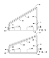
- FIG. 9 is a side view of the racking system of FIG. 1 in a fifth angled configuration
- FIG. 10 is a side view of the racking system of FIG. 1 in a sixth angled configuration
- FIG. 11 is a perspective view of an interconnection bar used to connect adjacent racking systems together;
- FIG. 12 is a cross-sectional view taken along line 12 - 12 of FIG. 11 ;
- FIG. 13 is a side view of two racking systems connected together according to an exemplary embodiment of the present invention.
- an embodiment of the present invention provides a light weight ballasted solar racking system that has light ballasted weight loads and is easy and fast to install.
- the racking system of the present invention may be used in roof or ground mount applications to mount thin film and frameless solar modules.
- the racking system physically attaches to the solar panel at the manufactured mounting holes with a set of struts that then attach to a ballast tray that holds the system in place.
- a set of struts may determine the degree of angle from about 5 to about 35 degrees, for example.
- the front of the ballast tray has an air pass way of about 3-5 inches, while the back of the system has about 8-12 inches of space for an air pass way.
- Multiple racking systems may be linked together, resulting in the need for less ballast weight for each racking system.
- a racking system may include a ballast pan 16 shaped in a U-shape, where the base of the U-shape is adapted to rest on a roof of on the ground, for example.
- a front side of the U-shape may be shorter than a back side of the U-shape.
- the base of the ballast pan 16 may be adapted to hold one or more ballast blocks 10 .
- the ballast pan 16 may be fabricated from aluminum, although other materials, such as steel, stainless steel, and plastic, may be used.
- the ballast pan 16 may be made in various thicknesses.
- 0.063 gauge aluminum may be used.
- the ballast pan 16 may be fabricated from a flat piece of material that is sheared to size and bent to shape.
- the sides of the ballast pan 16 may extend generally perpendicular from the base of the ballast pan 16 .
- the footprint of the ballast pan 16 may be the same or larger than the footprint of a solar panel 12 mounted on the racking system.
- the ballast pan 16 may include a hat channel, for example, bent from the same material and attached to the bottom to accommodate installations on the ground. Hat channels can be fabricated in varying heights, depending on system mounting concerns.
- a foam board 18 may be disposed on the bottom of the ballast pan 16 to separate the metal ballast pan 16 from roofing material.
- the foam board 18 may also promote proper water drainage of the racking system when installed on roofs.
- the foam board 18 can be utilized in varying thickness, rigidity, and resiliency to accommodate different roof concerns.
- a mounting strut 14 may extend generally perpendicular from the base of the ballast pan 16 at one side of the ballast pan 16 , may be bent at an appropriate angle (relative to the roof) and may be further bent to extend to the other side of the ballast pan 16 , again meeting the ballast pan in a generally perpendicular fashion.
- the mounting strut may be attached to the ballast pan 16 by using a bolt 44 , nut 50 and star washer 48 .
- Other attachment mechanisms such as sheet metal screws, may be used in place of the nut 50 and bolt 44 .
- the mounting strut 14 may be made of the same material as the ballast pan 16 . In some embodiments, the mounting strut 14 may be a material different from the material of the ballast pan 16 .
- the mounting strut 14 may be made from flat sheets of aluminum, for example. The sheets may be punched, notched and bent to the proper angle and size. The final bends which determine the solar module mounting angle may be mechanically secured with a sleet metal screw or rivet, or may be welded to maintain the structural integrity.
- mounting struts 14 may be used on each racking system. As shown in FIG. 1 , two mounting struts 14 may be used.
- the mounting strut 14 may contain two punched holes which align with the solar module manufacturer supplied frame mounting holes to secure the struts 14 to the solar module 12 using four solar module attachment fasteners 42 , for example. Other mechanisms may be used to attach the solar module 12 to the mounting struts 14 .
- the struts 14 and ballast pan 16 may be designed, for example, to provide an angle of about 25 degrees relative to the mounting surface (such as the ground or a roof).
- a 5 degree mounting strut 22 and a 5 degree ballast pan 24 may provide a 5 degree angle for the solar module 12 .
- a 10 degree mounting strut 26 and a 10 degree ballast pan 28 may provide a 10 degree angle for the solar module 12 .
- a 15 degree mounting strut 30 and a 15 degree ballast pan 32 may provide a 15 degree angle for the solar module 12 .
- a 20 degree mounting strut 34 and a 20 degree ballast pan 36 may provide a 20 degree angle for the solar module 12 .
- a 30 degree mounting strut 38 and a 30 degree ballast pan 40 may provide a 30 degree angle for the solar module 12 .
- Other angles may be envisioned within the scope of the present invention by changing the sizes of the struts and ballast pan. In some embodiments, the same size and shape ballast pan may be used with different sized struts to vary the angle of the solar module 12 .
- multiple racking systems may be interconnected with one or more interconnection bars 46 .
- the interconnection bars 46 may be L-shaped or T-shaped, for example.
- the interconnection bars 46 may be made of various lengths and may be installed in the space between the rows of ballast pans, connecting one ballast pan to a ballast pan in an adjacent row.
- the interconnection bars 46 may also be used to join racking systems side-by-side.
- Various connection mechanisms may be used to attach the interconnection bars 46 to the ballast pans.
- Proper electrical ground may be provided for the racking systems of the present invention.
- a grounding washers and grounding clips may be used to provide a continuous grounding path for each or multiple rows of ballast pans.
- Other electrical grounding mechanisms may be used to comply with national or local electric codes.
Abstract
A light weight ballasted solar racking system has light ballasted weight loads and is easy and fast to install. The racking system may be used in roof or ground mount applications to mount thin film and frameless solar modules. The racking system physically attaches to the solar panel at the manufactured mounting holes with a set of struts that then attach to a ballast tray that holds the system in place. A set of struts may determine the degree of angle from about 5 to about 35 degrees, for example. The front of the ballast tray has an air pass way of about 3-5 inches, while the back of the system has about 8-12 inches of space for an air pass way. Multiple racking systems may be linked together, resulting in the need for less ballast weight for each racking system.
Description
The present invention relates to solar panel racking systems and, more particularly, to a ballasted roof or ground mounted solar panel racking system.
Conventional solar panel racking systems attach directly to the roof or use a concrete curb system that sits on the roof and can potentially damage the roof surface. These conventional mounting systems are often time consuming to build and install, often resulting in leaks in the roof surface over time.
As can be seen, there is a need for an improved solar panel racking system.
In one aspect of the present invention, a racking system for a solar panel comprises a ballast pan having a base and first and second side extending from each side of the base; a mounting strut extending along the first side of the ballast pan, running at an angle relative to the base of the ballast pan, and extending along the second side of the ballast pan; and one or more ballast blocks disposed on the ballast pan.
In another aspect of the present invention, a racking system for a solar panel comprises a ballast pan having a base and first and second side extending from each side of the base; a mounting strut extending along the first side of the ballast pan, running at an angle relative to the base of the ballast pan, and extending along the second side of the ballast pan; one or more ballast blocks disposed on the ballast pan; a foam board disposed under the ballast pan; and a solar module attachment fastener adapted to connect the mounting strut to a solar module.
In a further aspect of the present invention, a method for mounting a solar module on a surface comprises disposing a ballast pan, having a base and first and second side extending from each side of the base, on the surface; extending a mounting strut along the first side of the ballast pan, running at an angle relative to the base of the ballast pan, and extending along the second side of the ballast pan; securing the mounting strut to the first and second sides of the ballast pan; placing one or more ballast blocks on the ballast pan; and attaching the solar module to the mounting strut.
These and other features, aspects and advantages of the present invention will become better understood with reference to the following drawings, description and claims.
The following detailed description is of the best currently contemplated modes of carrying out exemplary embodiments of the invention. The description is not to be taken in a limiting sense, but is made merely for the purpose of illustrating the general principles of the invention, since the scope of the invention is best defined by the appended claims.
Broadly, an embodiment of the present invention provides a light weight ballasted solar racking system that has light ballasted weight loads and is easy and fast to install. The racking system of the present invention may be used in roof or ground mount applications to mount thin film and frameless solar modules. The racking system physically attaches to the solar panel at the manufactured mounting holes with a set of struts that then attach to a ballast tray that holds the system in place. A set of struts may determine the degree of angle from about 5 to about 35 degrees, for example. The front of the ballast tray has an air pass way of about 3-5 inches, while the back of the system has about 8-12 inches of space for an air pass way. Multiple racking systems may be linked together, resulting in the need for less ballast weight for each racking system.
Referring now to FIGS. 1 through 5 , a racking system may include a ballast pan 16 shaped in a U-shape, where the base of the U-shape is adapted to rest on a roof of on the ground, for example. A front side of the U-shape may be shorter than a back side of the U-shape. The base of the ballast pan 16 may be adapted to hold one or more ballast blocks 10.
The ballast pan 16 may be fabricated from aluminum, although other materials, such as steel, stainless steel, and plastic, may be used. The ballast pan 16 may be made in various thicknesses. For an aluminum ballast pan, for example, 0.063 gauge aluminum may be used. The ballast pan 16 may be fabricated from a flat piece of material that is sheared to size and bent to shape. The sides of the ballast pan 16 may extend generally perpendicular from the base of the ballast pan 16. The footprint of the ballast pan 16 may be the same or larger than the footprint of a solar panel 12 mounted on the racking system.
The ballast pan 16 may include a hat channel, for example, bent from the same material and attached to the bottom to accommodate installations on the ground. Hat channels can be fabricated in varying heights, depending on system mounting concerns.
A foam board 18 may be disposed on the bottom of the ballast pan 16 to separate the metal ballast pan 16 from roofing material. The foam board 18 may also promote proper water drainage of the racking system when installed on roofs. The foam board 18 can be utilized in varying thickness, rigidity, and resiliency to accommodate different roof concerns.
A mounting strut 14 may extend generally perpendicular from the base of the ballast pan 16 at one side of the ballast pan 16, may be bent at an appropriate angle (relative to the roof) and may be further bent to extend to the other side of the ballast pan 16, again meeting the ballast pan in a generally perpendicular fashion. The mounting strut may be attached to the ballast pan 16 by using a bolt 44, nut 50 and star washer 48. Other attachment mechanisms, such as sheet metal screws, may be used in place of the nut 50 and bolt 44.
The mounting strut 14 may be made of the same material as the ballast pan 16. In some embodiments, the mounting strut 14 may be a material different from the material of the ballast pan 16. The mounting strut 14 may be made from flat sheets of aluminum, for example. The sheets may be punched, notched and bent to the proper angle and size. The final bends which determine the solar module mounting angle may be mechanically secured with a sleet metal screw or rivet, or may be welded to maintain the structural integrity.
From one to four, or more, mounting struts 14 may be used on each racking system. As shown in FIG. 1 , two mounting struts 14 may be used.
The mounting strut 14 may contain two punched holes which align with the solar module manufacturer supplied frame mounting holes to secure the struts 14 to the solar module 12 using four solar module attachment fasteners 42, for example. Other mechanisms may be used to attach the solar module 12 to the mounting struts 14.
The struts 14 and ballast pan 16 may be designed, for example, to provide an angle of about 25 degrees relative to the mounting surface (such as the ground or a roof). Referring to FIG. 6 , a 5 degree mounting strut 22 and a 5 degree ballast pan 24 may provide a 5 degree angle for the solar module 12. Referring to FIG. 7 , a 10 degree mounting strut 26 and a 10 degree ballast pan 28 may provide a 10 degree angle for the solar module 12. Referring to FIG. 8 , a 15 degree mounting strut 30 and a 15 degree ballast pan 32 may provide a 15 degree angle for the solar module 12. Referring to FIG. 9 , a 20 degree mounting strut 34 and a 20 degree ballast pan 36 may provide a 20 degree angle for the solar module 12. Referring to FIG. 10 , a 30 degree mounting strut 38 and a 30 degree ballast pan 40 may provide a 30 degree angle for the solar module 12. Other angles may be envisioned within the scope of the present invention by changing the sizes of the struts and ballast pan. In some embodiments, the same size and shape ballast pan may be used with different sized struts to vary the angle of the solar module 12.
Referring now to FIGS. 11 through 13 , multiple racking systems may be interconnected with one or more interconnection bars 46. The interconnection bars 46 may be L-shaped or T-shaped, for example. The interconnection bars 46 may be made of various lengths and may be installed in the space between the rows of ballast pans, connecting one ballast pan to a ballast pan in an adjacent row. The interconnection bars 46 may also be used to join racking systems side-by-side. Various connection mechanisms may be used to attach the interconnection bars 46 to the ballast pans.
Proper electrical ground may be provided for the racking systems of the present invention. For example, a grounding washers and grounding clips may be used to provide a continuous grounding path for each or multiple rows of ballast pans. Other electrical grounding mechanisms may be used to comply with national or local electric codes.
It should be understood, of course, that the foregoing relates to exemplary embodiments of the invention and that modifications may be made without departing from the spirit and scope of the invention as set forth in the following claims.
Claims (10)
1. A racking system for a solar panel comprising:
a ballast pan having a base and first and second sides extending from opposite ends of the base, wherein the second side extends higher than the first side;
a mounting strut having a first section extending along the first side of the ballast pan such that the first side of the ballast pan extends along at least a quarter of the length of the first section of the strut, a second section running at an angle relative to the base of the ballast pan, and a third section extending along the second side of the ballast pan such that the second side of the ballast pan extends along at least a quarter of the length of the third section of the strut, wherein a first gap is defined between an end of the first side of the ballast pan and an end portion of the second section of the strut proximate the first section and a second gap is defined between an end of the second side of the ballast pan and an end portion of the second section of the strut proximate the third section such that the second gap is larger than the first gap; and
one or more ballast blocks disposed on the ballast pan.
2. The racking system of claim 1 , further comprising a foam board disposed under the ballast pan.
3. The racking system of claim 1 , further comprising a solar module attachment fastener adapted to connect the mounting strut to a solar module.
4. The racking system of claim 1 , further comprising an interconnection bar attached to the ballast pan of a first racking system and the ballast pan of a second, adjacent racking system.
5. The racking system of claim 1 , wherein the angle is from about 5 degrees to about 35 degrees.
6. A racking system for a solar panel comprising:
a ballast pan having a base and first and second sides extending from opposite ends of the base, wherein the second side extends higher than the first side;
a mounting strut having a first section extending along the first side of the ballast pan such that the first side of the ballast pan extends along at least a quarter of the length of the first section of the strut, a second section running at an angle relative to the base of the ballast pan, and a third section extending along the second side of the ballast pan such that the second side of the ballast pan extends along at least a quarter of the length of the third section of the strut, wherein a first gap is defined between an end of the first side of the ballast pan and an end portion of the second section of the strut proximate the first section and a second gap is defined between an end of the second side of the ballast pan and an end portion of the second section of the strut proximate the third section such that the second gap is larger than the first gap;
one or more ballast blocks disposed on the ballast pan;
a foam board disposed under the ballast pan; and
a solar module attachment fastener adapted to connect the mounting strut to a solar module.
7. The racking system of claim 6 , further comprising an interconnection bar attached to the ballast pan of a first racking system and the ballast pan of a second, adjacent racking system.
8. The racking system of claim 6 , wherein the angle is from about 5 degrees to about 35 degrees.
9. A method for mounting a solar module on a surface, the method comprising:
disposing a ballast pan on the surface, the ballast pan having a base and first and second sides extending from opposite ends of the base, wherein the second side extends higher than the first side ;
providing a mounting strut having a first section extending along the first side of the ballast pan such that the first side of the ballast pan extends along at least a quarter of the length of the first section of the strut, a second section running at an angle relative to the base of the ballast pan, and a third section extending along the second side of the ballast pan such that the second side of the ballast pan extends along at least a quarter of the length of the third section of the strut, wherein a first gap is defined between an end of the first side of the ballast pan and an end portion of the second section of the strut proximate the first section and a second gap is defined between an end of the second side of the ballast pan and an end portion of the second section of the strut proximate the third section such that the second gap is larger than the first gap;
securing the mounting strut to the first and second sides of the ballast pan;
placing one or more ballast blocks on the ballast pan; and
attaching the solar module to the mounting strut.
10. The method of claim 9 , further comprising adjusting the size of the mounting strut such that a predetermined angle, with respect to the ballast base, is formed to mount the solar module thereupon.
Priority Applications (2)
| Application Number | Priority Date | Filing Date | Title |
|---|---|---|---|
| US13/365,168 US8661748B2 (en) | 2012-02-02 | 2012-02-02 | Ballasted roof and ground mounted solar panel racking system |
| US13/523,884 US20130200018A1 (en) | 2012-02-02 | 2012-06-15 | Ballasted roof and ground mounted solar panel racking system |
Applications Claiming Priority (1)
| Application Number | Priority Date | Filing Date | Title |
|---|---|---|---|
| US13/365,168 US8661748B2 (en) | 2012-02-02 | 2012-02-02 | Ballasted roof and ground mounted solar panel racking system |
Related Child Applications (1)
| Application Number | Title | Priority Date | Filing Date |
|---|---|---|---|
| US13/523,884 Continuation-In-Part US20130200018A1 (en) | 2012-02-02 | 2012-06-15 | Ballasted roof and ground mounted solar panel racking system |
Publications (2)
| Publication Number | Publication Date |
|---|---|
| US20130200016A1 US20130200016A1 (en) | 2013-08-08 |
| US8661748B2 true US8661748B2 (en) | 2014-03-04 |
Family
ID=48901972
Family Applications (1)
| Application Number | Title | Priority Date | Filing Date |
|---|---|---|---|
| US13/365,168 Expired - Fee Related US8661748B2 (en) | 2012-02-02 | 2012-02-02 | Ballasted roof and ground mounted solar panel racking system |
Country Status (1)
| Country | Link |
|---|---|
| US (1) | US8661748B2 (en) |
Cited By (4)
| Publication number | Priority date | Publication date | Assignee | Title |
|---|---|---|---|---|
| US20130032208A1 (en) * | 2011-08-04 | 2013-02-07 | Leo Walz | Flat-roof mounting system for photovoltaic modules |
| USD801265S1 (en) * | 2013-03-22 | 2017-10-31 | Universiti Malaya | Solar plate |
| US20170350622A1 (en) * | 2016-06-06 | 2017-12-07 | Angel M. Rivera | Solar racking system adapted for suspended ballasting |
| US9923508B2 (en) | 2015-02-26 | 2018-03-20 | Cowatt Energy, LLC. | Mounting unit for solar electricity generation systems and improved installation method |
Families Citing this family (4)
| Publication number | Priority date | Publication date | Assignee | Title |
|---|---|---|---|---|
| US9163861B2 (en) | 2012-10-01 | 2015-10-20 | Georgia Tech Research Corporation | Solar panel truss mounting systems and methods |
| WO2017007736A1 (en) * | 2015-07-04 | 2017-01-12 | Jan Kunczynski | Ballasted mount for pv panels |
| US10250181B2 (en) | 2015-10-15 | 2019-04-02 | RBI Solar, Inc. | Solar panel support devices and related solar panel support systems |
| CN107617853A (en) * | 2017-08-23 | 2018-01-23 | 成都飞机工业(集团)有限责任公司 | A kind of processing method of stainless sheet steel part thickness control |
Citations (47)
| Publication number | Priority date | Publication date | Assignee | Title |
|---|---|---|---|---|
| US4058111A (en) | 1975-07-16 | 1977-11-15 | James L. Lowe | Solar collector |
| US4226256A (en) * | 1979-09-18 | 1980-10-07 | Atlantic Richfield Company | Solar panel assembly and support pad |
| US4292957A (en) | 1979-11-23 | 1981-10-06 | Golder John C | Solar oven |
| US4300537A (en) | 1980-09-19 | 1981-11-17 | Davis Thomas A | Solar panel mount |
| US4306544A (en) | 1980-03-20 | 1981-12-22 | Clemens Mark H | Solar water heater |
| US4378006A (en) | 1979-08-13 | 1983-03-29 | Atlantic Richfield Company | Solar panel foundation device |
| US4421943A (en) * | 1982-02-19 | 1983-12-20 | Cities Service Company | Collapsible mobile solar energy power source |
| US4440861A (en) | 1980-09-15 | 1984-04-03 | Entropy Dynamics | Solar apparatus and process |
| US4716882A (en) | 1981-10-14 | 1988-01-05 | Yazaki Corporation | Solar heat collector |
| US4832001A (en) | 1987-05-28 | 1989-05-23 | Zomeworks Corporation | Lightweight solar panel support |
| US5125608A (en) | 1989-04-25 | 1992-06-30 | 700 Solar Club, Inc. | Photovoltaic panel support assembly |
| US5139010A (en) | 1991-02-14 | 1992-08-18 | The Solar Gourmet Corporation | Solar oven |
| US5232187A (en) | 1992-08-10 | 1993-08-03 | Farrell John B O | Painter's helper |
| US5289999A (en) | 1990-07-04 | 1994-03-01 | Schottel Werft Joseph Becker Gmbh & Co. Kg | Apparatus for mounting solar cells |
| US5505788A (en) | 1994-06-29 | 1996-04-09 | Dinwoodie; Thomas L. | Thermally regulated photovoltaic roofing assembly |
| US5768831A (en) | 1993-09-16 | 1998-06-23 | Blue Planet Ag | Rooftile support for photocell panel |
| EP0857296A1 (en) | 1995-10-24 | 1998-08-12 | Lockheed-Martin IR Imaging Systems | Uncooled focal plane array sensor |
| DE29910538U1 (en) | 1999-06-16 | 1999-09-16 | Peer Percy Schoenau | Solar tub |
| US5953869A (en) | 1997-10-10 | 1999-09-21 | Sun Systems, Inc. | Framing system for flush mounting objects to a roof and method therefor |
| JP2000208803A (en) | 1999-01-18 | 2000-07-28 | Misawa Homes Co Ltd | Solar cell module |
| DE20008509U1 (en) | 2000-05-11 | 2000-08-10 | Phoenix Sonnenstrom Ag | Support arrangement |
| US6105316A (en) | 1997-02-06 | 2000-08-22 | Cooperatief Advies En Onderzoeksburo U.A. Ecofys | Device for supporting solar panel and a solar panel assembly comprising this device |
| US6105317A (en) | 1997-09-24 | 2000-08-22 | Matsushita Electric Works, Ltd. | Mounting system for installing an array of solar battery modules of a panel-like configuration on a roof |
| US20010008143A1 (en) * | 1998-05-20 | 2001-07-19 | Makoto Sasaoka | Photovoltaic power generating structure |
| US6346669B1 (en) | 1998-07-08 | 2002-02-12 | Misawa Homes Co., Ltd. | Solar battery unit and solar battery apparatus |
| US6360491B1 (en) | 2000-01-14 | 2002-03-26 | Stanley A. Ullman | Roof support system for a solar panel |
| US6370828B1 (en) | 1999-07-19 | 2002-04-16 | Regen Energiesysteme Gmbh | Mounting system for solar panel |
| DE20120983U1 (en) | 2001-12-27 | 2002-04-18 | Schoenau Ag | Modulhalter |
| US20020092246A1 (en) | 2001-01-18 | 2002-07-18 | Graham William D. | Foldable sheet for forming support structure on roof |
| US6534702B1 (en) | 1997-11-13 | 2003-03-18 | Canon Kabushiki Kaisha | Solar battery module arranging method and solar battery module array |
| US20030070368A1 (en) | 2001-10-12 | 2003-04-17 | Jefferson Shingleton | Solar module mounting method and clip |
| WO2003038910A2 (en) | 2001-10-29 | 2003-05-08 | Bp Solar Limited | Low ballast mounting system |
| USD496248S1 (en) | 2003-08-18 | 2004-09-21 | Unirac, Inc. | Modified standard rail |
| USD496249S1 (en) | 2003-06-09 | 2004-09-21 | Unirac, Inc. | Heavy-duty rail |
| US20040261334A1 (en) | 2003-02-26 | 2004-12-30 | Liebendorfer John E | System for mounting a device on a pole |
| US20050166955A1 (en) * | 2004-01-29 | 2005-08-04 | Prem Nath | Support system for photovoltaic device and method for its use |
| US6968654B2 (en) | 2003-01-08 | 2005-11-29 | Mcconnell Energy Solutions, Llc | Solar panel mounting structure, solar panel system, and methods of making and installing thereof |
| US20070102036A1 (en) | 2004-05-18 | 2007-05-10 | Andalay Solar, Inc. | Mounting system for a solar panel |
| US7260918B2 (en) | 2001-07-20 | 2007-08-28 | Unirac, Inc. | Apparatus and method for positioning a module on an object |
| US20090134291A1 (en) * | 2007-11-20 | 2009-05-28 | Meier Chris M | System and method of mounting a removable and adjustable photovoltaic ballast frame device |
| US20090232616A1 (en) | 2008-03-07 | 2009-09-17 | Unirac, Inc. | Friction Lock Bolt |
| US20100269447A1 (en) | 2009-04-27 | 2010-10-28 | Nathan Schuit | Snap-on structural connector |
| US7849849B2 (en) * | 2005-02-14 | 2010-12-14 | Conergy Ag | Frame assembly for mounting solar modules |
| US20100319277A1 (en) | 2009-06-19 | 2010-12-23 | Unirac, Inc. | Modular structural framing system |
| US20120036799A1 (en) * | 2010-08-12 | 2012-02-16 | Centrosolar AG | Support device for mounting a solar panel and mounting system incorporating same |
| US20120048351A1 (en) | 2009-05-13 | 2012-03-01 | Solar Liberty Energy Systems, Inc. | Solar panel racking assembly |
| USD671885S1 (en) * | 2011-09-21 | 2012-12-04 | miniJOULE GmbH & Co. KG | Solar panel |
-
2012
- 2012-02-02 US US13/365,168 patent/US8661748B2/en not_active Expired - Fee Related
Patent Citations (54)
| Publication number | Priority date | Publication date | Assignee | Title |
|---|---|---|---|---|
| US4058111A (en) | 1975-07-16 | 1977-11-15 | James L. Lowe | Solar collector |
| US4378006A (en) | 1979-08-13 | 1983-03-29 | Atlantic Richfield Company | Solar panel foundation device |
| US4226256A (en) * | 1979-09-18 | 1980-10-07 | Atlantic Richfield Company | Solar panel assembly and support pad |
| US4292957A (en) | 1979-11-23 | 1981-10-06 | Golder John C | Solar oven |
| US4306544A (en) | 1980-03-20 | 1981-12-22 | Clemens Mark H | Solar water heater |
| US4440861A (en) | 1980-09-15 | 1984-04-03 | Entropy Dynamics | Solar apparatus and process |
| US4300537A (en) | 1980-09-19 | 1981-11-17 | Davis Thomas A | Solar panel mount |
| US4716882A (en) | 1981-10-14 | 1988-01-05 | Yazaki Corporation | Solar heat collector |
| US4421943A (en) * | 1982-02-19 | 1983-12-20 | Cities Service Company | Collapsible mobile solar energy power source |
| US4832001A (en) | 1987-05-28 | 1989-05-23 | Zomeworks Corporation | Lightweight solar panel support |
| US5125608A (en) | 1989-04-25 | 1992-06-30 | 700 Solar Club, Inc. | Photovoltaic panel support assembly |
| US5289999A (en) | 1990-07-04 | 1994-03-01 | Schottel Werft Joseph Becker Gmbh & Co. Kg | Apparatus for mounting solar cells |
| US5139010A (en) | 1991-02-14 | 1992-08-18 | The Solar Gourmet Corporation | Solar oven |
| US5232187A (en) | 1992-08-10 | 1993-08-03 | Farrell John B O | Painter's helper |
| US5768831A (en) | 1993-09-16 | 1998-06-23 | Blue Planet Ag | Rooftile support for photocell panel |
| US5505788A (en) | 1994-06-29 | 1996-04-09 | Dinwoodie; Thomas L. | Thermally regulated photovoltaic roofing assembly |
| EP0857296A1 (en) | 1995-10-24 | 1998-08-12 | Lockheed-Martin IR Imaging Systems | Uncooled focal plane array sensor |
| US6105316A (en) | 1997-02-06 | 2000-08-22 | Cooperatief Advies En Onderzoeksburo U.A. Ecofys | Device for supporting solar panel and a solar panel assembly comprising this device |
| US6105317A (en) | 1997-09-24 | 2000-08-22 | Matsushita Electric Works, Ltd. | Mounting system for installing an array of solar battery modules of a panel-like configuration on a roof |
| US5953869A (en) | 1997-10-10 | 1999-09-21 | Sun Systems, Inc. | Framing system for flush mounting objects to a roof and method therefor |
| US6534702B1 (en) | 1997-11-13 | 2003-03-18 | Canon Kabushiki Kaisha | Solar battery module arranging method and solar battery module array |
| US20010008143A1 (en) * | 1998-05-20 | 2001-07-19 | Makoto Sasaoka | Photovoltaic power generating structure |
| US6346669B1 (en) | 1998-07-08 | 2002-02-12 | Misawa Homes Co., Ltd. | Solar battery unit and solar battery apparatus |
| JP2000208803A (en) | 1999-01-18 | 2000-07-28 | Misawa Homes Co Ltd | Solar cell module |
| DE29910538U1 (en) | 1999-06-16 | 1999-09-16 | Peer Percy Schoenau | Solar tub |
| US6370828B1 (en) | 1999-07-19 | 2002-04-16 | Regen Energiesysteme Gmbh | Mounting system for solar panel |
| US6360491B1 (en) | 2000-01-14 | 2002-03-26 | Stanley A. Ullman | Roof support system for a solar panel |
| DE20008509U1 (en) | 2000-05-11 | 2000-08-10 | Phoenix Sonnenstrom Ag | Support arrangement |
| US20020092246A1 (en) | 2001-01-18 | 2002-07-18 | Graham William D. | Foldable sheet for forming support structure on roof |
| US7766292B2 (en) | 2001-07-20 | 2010-08-03 | Unirac, Inc. | System for mounting a photovoltaic module to a surface |
| US8128044B2 (en) | 2001-07-20 | 2012-03-06 | Unirac, Inc. | System for mounting a photovoltaic module to a surface |
| US7260918B2 (en) | 2001-07-20 | 2007-08-28 | Unirac, Inc. | Apparatus and method for positioning a module on an object |
| US7434362B2 (en) | 2001-07-20 | 2008-10-14 | Unirac, Inc. | System for removably and adjustably mounting a device on a surface |
| US20030070368A1 (en) | 2001-10-12 | 2003-04-17 | Jefferson Shingleton | Solar module mounting method and clip |
| WO2003038910A2 (en) | 2001-10-29 | 2003-05-08 | Bp Solar Limited | Low ballast mounting system |
| US20040250491A1 (en) | 2001-10-29 | 2004-12-16 | Diaz Emilio Mera | Low ballast mounting system |
| DE20120983U1 (en) | 2001-12-27 | 2002-04-18 | Schoenau Ag | Modulhalter |
| US6968654B2 (en) | 2003-01-08 | 2005-11-29 | Mcconnell Energy Solutions, Llc | Solar panel mounting structure, solar panel system, and methods of making and installing thereof |
| US7748175B2 (en) | 2003-02-26 | 2010-07-06 | Unirac, Inc. | Method of manufacturing and installing a low profile mounting system |
| US20040261334A1 (en) | 2003-02-26 | 2004-12-30 | Liebendorfer John E | System for mounting a device on a pole |
| US7600349B2 (en) | 2003-02-26 | 2009-10-13 | Unirac, Inc. | Low profile mounting system |
| USD496249S1 (en) | 2003-06-09 | 2004-09-21 | Unirac, Inc. | Heavy-duty rail |
| USD496248S1 (en) | 2003-08-18 | 2004-09-21 | Unirac, Inc. | Modified standard rail |
| US20050166955A1 (en) * | 2004-01-29 | 2005-08-04 | Prem Nath | Support system for photovoltaic device and method for its use |
| US20070102036A1 (en) | 2004-05-18 | 2007-05-10 | Andalay Solar, Inc. | Mounting system for a solar panel |
| US7832157B2 (en) * | 2004-05-18 | 2010-11-16 | Andalay Solar, Inc. | Mounting system for a solar panel |
| US7849849B2 (en) * | 2005-02-14 | 2010-12-14 | Conergy Ag | Frame assembly for mounting solar modules |
| US20090134291A1 (en) * | 2007-11-20 | 2009-05-28 | Meier Chris M | System and method of mounting a removable and adjustable photovoltaic ballast frame device |
| US20090232616A1 (en) | 2008-03-07 | 2009-09-17 | Unirac, Inc. | Friction Lock Bolt |
| US20100269447A1 (en) | 2009-04-27 | 2010-10-28 | Nathan Schuit | Snap-on structural connector |
| US20120048351A1 (en) | 2009-05-13 | 2012-03-01 | Solar Liberty Energy Systems, Inc. | Solar panel racking assembly |
| US20100319277A1 (en) | 2009-06-19 | 2010-12-23 | Unirac, Inc. | Modular structural framing system |
| US20120036799A1 (en) * | 2010-08-12 | 2012-02-16 | Centrosolar AG | Support device for mounting a solar panel and mounting system incorporating same |
| USD671885S1 (en) * | 2011-09-21 | 2012-12-04 | miniJOULE GmbH & Co. KG | Solar panel |
Non-Patent Citations (5)
| Title |
|---|
| Elektriciteit uit zonlicht, Feb. 7, 1996, http://www.ode.be. |
| Hacker, Rod, Ruyssevelt Paul, Munro Donna, "Activity Leader and Information Dissemination", Crown, First published 2002. |
| Installation Manual for ConSole, from Econergy International B.V., 2007, available at www.e-conergy.com. |
| Roecker, C. et al. "Demosite & Demosite Flat Roofs in IEA Task VII(PVPS)" Ecole Polytechnique Fédérale de Lausanne (EPFL), Laboratoire d'Energie Solaire et de Physique du B{hacek over (a)}timent. |
| Roecker, Christian, "New Mounting Systems for PV on Buildings", The 2nd World Solar Electric Buildings Conference, Sydney Mar. 8-10, 2000, pp. 1-8. |
Cited By (6)
| Publication number | Priority date | Publication date | Assignee | Title |
|---|---|---|---|---|
| US20130032208A1 (en) * | 2011-08-04 | 2013-02-07 | Leo Walz | Flat-roof mounting system for photovoltaic modules |
| US9093948B2 (en) * | 2011-08-04 | 2015-07-28 | Creotecc Gmbh | Flat-roof mounting system for photovoltaic modules |
| USD801265S1 (en) * | 2013-03-22 | 2017-10-31 | Universiti Malaya | Solar plate |
| US9923508B2 (en) | 2015-02-26 | 2018-03-20 | Cowatt Energy, LLC. | Mounting unit for solar electricity generation systems and improved installation method |
| US20170350622A1 (en) * | 2016-06-06 | 2017-12-07 | Angel M. Rivera | Solar racking system adapted for suspended ballasting |
| US9982917B2 (en) * | 2016-06-06 | 2018-05-29 | Solar Mounting Solutions, LLC | Solar racking system adapted for suspended ballasting |
Also Published As
| Publication number | Publication date |
|---|---|
| US20130200016A1 (en) | 2013-08-08 |
Similar Documents
| Publication | Publication Date | Title |
|---|---|---|
| US8661748B2 (en) | Ballasted roof and ground mounted solar panel racking system | |
| US8850754B2 (en) | Molded solar panel racking assembly | |
| US10365017B2 (en) | Self-adjusting end clamp | |
| US9551510B2 (en) | Slider clip and photovoltaic structure mounting system | |
| US8844215B2 (en) | Support assembly for supporting photovoltaic modules | |
| US7806377B2 (en) | Modular solar panel mounting system | |
| US9175704B2 (en) | Panel clamping and mounting mechanism | |
| JP4726878B2 (en) | Mounting structure for solar cell module and exterior panel | |
| US20120175322A1 (en) | Panel Mounting System and Method | |
| US20210270301A1 (en) | Panel clamping and mounting mechanism | |
| US9559631B2 (en) | Clamp assembly for solar panels | |
| US10355636B2 (en) | Structure and support device for photovoltaic arrays | |
| US9276518B2 (en) | Panel support structure | |
| US20120211252A1 (en) | Solar Panel Racking System with Integrated Grounding Bar Rail | |
| WO2016069488A2 (en) | Clamps for installation of photovoltaic modules to roofs | |
| JP4451576B2 (en) | Solar panel construction equipment | |
| US20130200018A1 (en) | Ballasted roof and ground mounted solar panel racking system | |
| WO2010133242A1 (en) | Mounting system for solar panels and connecting bracket for same | |
| US20130003274A1 (en) | Solar Panel Racking System With Integrated Grounding Bar Rail | |
| JP5602285B1 (en) | Solar cell module mounting structure of goby type folded plate roof | |
| US20150295533A1 (en) | Ballasted fixed tilt racking system | |
| CA2851813C (en) | Molded solar panel racking assembly | |
| KR101124440B1 (en) | Installation method of solar sell module | |
| JP6554442B2 (en) | Support bracket for solar panel mounting base | |
| US20130146549A1 (en) | Solar panel assembly kit and method of assembly |
Legal Events
| Date | Code | Title | Description |
|---|---|---|---|
| FEPP | Fee payment procedure |
Free format text: MAINTENANCE FEE REMINDER MAILED (ORIGINAL EVENT CODE: REM.) |
|
| LAPS | Lapse for failure to pay maintenance fees |
Free format text: PATENT EXPIRED FOR FAILURE TO PAY MAINTENANCE FEES (ORIGINAL EVENT CODE: EXP.) |
|
| STCH | Information on status: patent discontinuation |
Free format text: PATENT EXPIRED DUE TO NONPAYMENT OF MAINTENANCE FEES UNDER 37 CFR 1.362 |
|
| FP | Expired due to failure to pay maintenance fee |
Effective date: 20180304 |