US9331629B2 - Photovoltaic frame fastener - Google Patents
Photovoltaic frame fastener Download PDFInfo
- Publication number
- US9331629B2 US9331629B2 US13/539,814 US201213539814A US9331629B2 US 9331629 B2 US9331629 B2 US 9331629B2 US 201213539814 A US201213539814 A US 201213539814A US 9331629 B2 US9331629 B2 US 9331629B2
- Authority
- US
- United States
- Prior art keywords
- fastener
- strut
- opening
- tongue
- tabs
- Prior art date
- Legal status (The legal status is an assumption and is not a legal conclusion. Google has not performed a legal analysis and makes no representation as to the accuracy of the status listed.)
- Active, expires
Links
- 230000015572 biosynthetic process Effects 0.000 claims description 8
- 238000005755 formation reaction Methods 0.000 claims description 8
- 238000003780 insertion Methods 0.000 claims description 7
- 238000009434 installation Methods 0.000 claims description 6
- 239000011521 glass Substances 0.000 claims description 5
- 230000002093 peripheral effect Effects 0.000 claims description 5
- 229910052751 metal Inorganic materials 0.000 claims description 4
- 239000002184 metal Substances 0.000 claims description 4
- 230000037431 insertion Effects 0.000 claims description 3
- 238000000605 extraction Methods 0.000 claims 1
- 238000010276 construction Methods 0.000 description 7
- 239000000463 material Substances 0.000 description 3
- 229910000831 Steel Inorganic materials 0.000 description 2
- 238000013459 approach Methods 0.000 description 2
- 230000006835 compression Effects 0.000 description 2
- 238000007906 compression Methods 0.000 description 2
- 230000006378 damage Effects 0.000 description 2
- 238000004519 manufacturing process Methods 0.000 description 2
- 239000010959 steel Substances 0.000 description 2
- 229910000788 1018 steel Inorganic materials 0.000 description 1
- 241000276495 Melanogrammus aeglefinus Species 0.000 description 1
- 229910000639 Spring steel Inorganic materials 0.000 description 1
- 229910052782 aluminium Inorganic materials 0.000 description 1
- XAGFODPZIPBFFR-UHFFFAOYSA-N aluminium Chemical compound [Al] XAGFODPZIPBFFR-UHFFFAOYSA-N 0.000 description 1
- 239000011324 bead Substances 0.000 description 1
- 239000011248 coating agent Substances 0.000 description 1
- 238000000576 coating method Methods 0.000 description 1
- 230000014759 maintenance of location Effects 0.000 description 1
- 238000000034 method Methods 0.000 description 1
- 238000012986 modification Methods 0.000 description 1
- 230000004048 modification Effects 0.000 description 1
- 229910001220 stainless steel Inorganic materials 0.000 description 1
- 239000010935 stainless steel Substances 0.000 description 1
- 239000011800 void material Substances 0.000 description 1
Images


Classifications
-
- H—ELECTRICITY
- H02—GENERATION; CONVERSION OR DISTRIBUTION OF ELECTRIC POWER
- H02S—GENERATION OF ELECTRIC POWER BY CONVERSION OF INFRARED RADIATION, VISIBLE LIGHT OR ULTRAVIOLET LIGHT, e.g. USING PHOTOVOLTAIC [PV] MODULES
- H02S20/00—Supporting structures for PV modules
-
- H—ELECTRICITY
- H02—GENERATION; CONVERSION OR DISTRIBUTION OF ELECTRIC POWER
- H02S—GENERATION OF ELECTRIC POWER BY CONVERSION OF INFRARED RADIATION, VISIBLE LIGHT OR ULTRAVIOLET LIGHT, e.g. USING PHOTOVOLTAIC [PV] MODULES
- H02S20/00—Supporting structures for PV modules
- H02S20/20—Supporting structures directly fixed to an immovable object
- H02S20/22—Supporting structures directly fixed to an immovable object specially adapted for buildings
- H02S20/23—Supporting structures directly fixed to an immovable object specially adapted for buildings specially adapted for roof structures
-
- F24J2/5256—
-
- F—MECHANICAL ENGINEERING; LIGHTING; HEATING; WEAPONS; BLASTING
- F24—HEATING; RANGES; VENTILATING
- F24S—SOLAR HEAT COLLECTORS; SOLAR HEAT SYSTEMS
- F24S25/00—Arrangement of stationary mountings or supports for solar heat collector modules
- F24S25/60—Fixation means, e.g. fasteners, specially adapted for supporting solar heat collector modules
- F24S25/63—Fixation means, e.g. fasteners, specially adapted for supporting solar heat collector modules for fixing modules or their peripheral frames to supporting elements
- F24S25/634—Clamps; Clips
-
- F—MECHANICAL ENGINEERING; LIGHTING; HEATING; WEAPONS; BLASTING
- F16—ENGINEERING ELEMENTS AND UNITS; GENERAL MEASURES FOR PRODUCING AND MAINTAINING EFFECTIVE FUNCTIONING OF MACHINES OR INSTALLATIONS; THERMAL INSULATION IN GENERAL
- F16B—DEVICES FOR FASTENING OR SECURING CONSTRUCTIONAL ELEMENTS OR MACHINE PARTS TOGETHER, e.g. NAILS, BOLTS, CIRCLIPS, CLAMPS, CLIPS OR WEDGES; JOINTS OR JOINTING
- F16B7/00—Connections of rods or tubes, e.g. of non-circular section, mutually, including resilient connections
- F16B7/04—Clamping or clipping connections
- F16B7/044—Clamping or clipping connections for rods or tubes being in angled relationship
- F16B7/0446—Clamping or clipping connections for rods or tubes being in angled relationship for tubes using the innerside thereof
- F16B7/0473—Clamping or clipping connections for rods or tubes being in angled relationship for tubes using the innerside thereof with hook-like parts gripping, e.g. by expanding, behind the flanges of a profile
-
- F24J2002/4663—
-
- F24J2002/4665—
-
- F—MECHANICAL ENGINEERING; LIGHTING; HEATING; WEAPONS; BLASTING
- F24—HEATING; RANGES; VENTILATING
- F24S—SOLAR HEAT COLLECTORS; SOLAR HEAT SYSTEMS
- F24S25/00—Arrangement of stationary mountings or supports for solar heat collector modules
- F24S25/60—Fixation means, e.g. fasteners, specially adapted for supporting solar heat collector modules
- F24S2025/6003—Fixation means, e.g. fasteners, specially adapted for supporting solar heat collector modules by clamping
-
- F—MECHANICAL ENGINEERING; LIGHTING; HEATING; WEAPONS; BLASTING
- F24—HEATING; RANGES; VENTILATING
- F24S—SOLAR HEAT COLLECTORS; SOLAR HEAT SYSTEMS
- F24S25/00—Arrangement of stationary mountings or supports for solar heat collector modules
- F24S25/60—Fixation means, e.g. fasteners, specially adapted for supporting solar heat collector modules
- F24S2025/6004—Fixation means, e.g. fasteners, specially adapted for supporting solar heat collector modules by clipping, e.g. by using snap connectors
-
- Y—GENERAL TAGGING OF NEW TECHNOLOGICAL DEVELOPMENTS; GENERAL TAGGING OF CROSS-SECTIONAL TECHNOLOGIES SPANNING OVER SEVERAL SECTIONS OF THE IPC; TECHNICAL SUBJECTS COVERED BY FORMER USPC CROSS-REFERENCE ART COLLECTIONS [XRACs] AND DIGESTS
- Y02—TECHNOLOGIES OR APPLICATIONS FOR MITIGATION OR ADAPTATION AGAINST CLIMATE CHANGE
- Y02B—CLIMATE CHANGE MITIGATION TECHNOLOGIES RELATED TO BUILDINGS, e.g. HOUSING, HOUSE APPLIANCES OR RELATED END-USER APPLICATIONS
- Y02B10/00—Integration of renewable energy sources in buildings
- Y02B10/10—Photovoltaic [PV]
-
- Y02B10/12—
-
- Y—GENERAL TAGGING OF NEW TECHNOLOGICAL DEVELOPMENTS; GENERAL TAGGING OF CROSS-SECTIONAL TECHNOLOGIES SPANNING OVER SEVERAL SECTIONS OF THE IPC; TECHNICAL SUBJECTS COVERED BY FORMER USPC CROSS-REFERENCE ART COLLECTIONS [XRACs] AND DIGESTS
- Y02—TECHNOLOGIES OR APPLICATIONS FOR MITIGATION OR ADAPTATION AGAINST CLIMATE CHANGE
- Y02E—REDUCTION OF GREENHOUSE GAS [GHG] EMISSIONS, RELATED TO ENERGY GENERATION, TRANSMISSION OR DISTRIBUTION
- Y02E10/00—Energy generation through renewable energy sources
- Y02E10/40—Solar thermal energy, e.g. solar towers
- Y02E10/47—Mountings or tracking
-
- Y—GENERAL TAGGING OF NEW TECHNOLOGICAL DEVELOPMENTS; GENERAL TAGGING OF CROSS-SECTIONAL TECHNOLOGIES SPANNING OVER SEVERAL SECTIONS OF THE IPC; TECHNICAL SUBJECTS COVERED BY FORMER USPC CROSS-REFERENCE ART COLLECTIONS [XRACs] AND DIGESTS
- Y02—TECHNOLOGIES OR APPLICATIONS FOR MITIGATION OR ADAPTATION AGAINST CLIMATE CHANGE
- Y02E—REDUCTION OF GREENHOUSE GAS [GHG] EMISSIONS, RELATED TO ENERGY GENERATION, TRANSMISSION OR DISTRIBUTION
- Y02E10/00—Energy generation through renewable energy sources
- Y02E10/50—Photovoltaic [PV] energy
-
- Y—GENERAL TAGGING OF NEW TECHNOLOGICAL DEVELOPMENTS; GENERAL TAGGING OF CROSS-SECTIONAL TECHNOLOGIES SPANNING OVER SEVERAL SECTIONS OF THE IPC; TECHNICAL SUBJECTS COVERED BY FORMER USPC CROSS-REFERENCE ART COLLECTIONS [XRACs] AND DIGESTS
- Y10—TECHNICAL SUBJECTS COVERED BY FORMER USPC
- Y10T—TECHNICAL SUBJECTS COVERED BY FORMER US CLASSIFICATION
- Y10T403/00—Joints and connections
- Y10T403/54—Flexible member is joint component
Definitions
- the present disclosure relates generally to a fastener and more particularly to a photovoltaic frame fastener.
- peripheral mounting frames holding solar or photovoltaic panels are mounted to a supporting structure on a building roof or on the land through use of threaded fasteners and multi-piece brackets.
- Exemplary traditional devices are disclosed in U.S. Pat. No. 7,758,011 entitled “Adjustable Mounting Assembly for Standing Seam Panels” which issued to Haddock on Jul. 20, 2010, and U.S. Pat. No. 6,105,317 entitled “Mounting System For Installing an Array of Solar Battery Modules of a Panel-Like Configuration on a Roof” which issued to Tomiuchi et al. on Aug. 22, 2000.
- These patents are incorporated by reference herein.
- These devices however, have many loose parts, and are time consuming and complex to install on a job site, such as on top of a windy roof, which thereby incurs significant labor expense and effort.
- a photovoltaic frame fastener in one aspect, includes a strut or rail defining a generally U-shaped channel and a snap-in clip or fastener.
- a single-piece fastener includes a strut-engaging surface, at least one flexible wing matable with an opening in a strut, a flexible tongue internally projecting in a central manner from a top wall of a body, and a slot adapted to receive a portion of a photovoltaic panel frame.
- the central tongue has at least one formation for securing the frame in the slot.
- Yet another aspect of a photovoltaic frame fastener includes laterally projecting tabs abutting against a top of a strut.
- a bifurcated tongue is employed in an additional aspect.
- a method of attaching a photovoltaic frame to an elongated structure is also provided.
- the present photovoltaic frame fastener is advantageous over traditional devices.
- the one-piece nature of the present fastener is inexpensive and fast to manufacture, install and remove.
- the present fastener is suitable for pre-assembly to the frame offsite or at a manufacturing plant, thereby improving quality and reducing assembly cost.
- the present fastener advantageously hides the snap-in wing sections securing the frame and strut, thereby making theft and vandalism difficult.
- the retention forces are direction in-line thereby advantageously reducing torsion on the fastener which achieves a more secure attachment with less stress on the fastener, frame and solar panel, and requiring lower installation force.
- a more secure attachment is realized by reducing side-to-side and/or front-to-back tilting, while also preventing over-insertion of a fastener into a strut opening.
- FIG. 1 is a perspective view showing a photovoltaic frame fastener assembly mounted to a building roof;
- FIG. 2 is a perspective view showing a photovoltaic frame fastener assembly mounted to the ground;
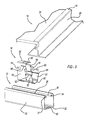
- FIG. 3 is an exploded perspective view showing a first preferred embodiment of a photovoltaic frame fastener assembly
- FIG. 4 is a perspective view showing the first embodiment photovoltaic frame fastener assembly
- FIG. 5 is a perspective view showing the first embodiment photovoltaic frame fastener assembly, taken opposite that of FIG. 4 ;
- FIG. 6 is a perspective view like that of FIG. 5 , showing the first embodiment photovoltaic frame fastener assembly, without a strut;
- FIG. 7 is a perspective view like that of FIG. 6 , showing the first embodiment photovoltaic frame fastener assembly, with an upper removal tool;
- FIG. 8 is a top elevational view showing the first embodiment photovoltaic frame fastener assembly, with the upper removal tool;
- FIG. 9 is a side elevational view showing one embodiment of a lower removal tool used with the photovoltaic frame fastener assembly
- FIG. 10 is a top elevational view showing a second embodiment of the lower removal tool used with the photovoltaic frame fastener assembly
- FIG. 11 is a side elevational view showing the lower removal tool of FIG. 10 ;
- FIG. 12 is a top elevational view showing the lower removal tool engaging the first embodiment fastener
- FIG. 13 is a perspective view showing the lower removal tool engaging the first embodiment fastener
- FIG. 14 is an end elevational view showing the lower removal tool initially contacting a second embodiment of a photovoltaic frame fastener
- FIG. 15 is an end elevational view like that of FIG. 14 , showing the lower removal tool inwardly compressing wings of the first embodiment fastener;
- FIG. 16 is a side elevational view showing the second embodiment photovoltaic frame fastener assembly
- FIG. 17 is an end elevational view showing the second embodiment photovoltaic frame fastener assembly
- FIG. 18 is a perspective view showing the second embodiment photovoltaic frame fastener
- FIG. 19 is a perspective view, taken opposite that of FIG. 18 , showing the second embodiment photovoltaic frame fastener
- FIG. 20 is a top elevational view showing the second embodiment photovoltaic frame fastener
- FIG. 21 is an end elevational view showing the second embodiment photovoltaic frame fastener
- FIG. 22 is a side elevational view showing the second embodiment photovoltaic frame fastener
- FIG. 23 is a cross-sectional view, taken along lines 23 - 23 of FIG. 22 , showing the second embodiment photovoltaic frame fastener;
- FIG. 24 is a top elevational view showing a flat blank used to create the second embodiment photovoltaic frame fastener
- FIG. 25 is a top elevational view showing the upper and lower removal tools used with the second embodiment photovoltaic frame fastener assembly
- FIG. 26 is a perspective view showing a third embodiment photovoltaic frame fastener assembly
- FIG. 27 is an end elevational view showing the third embodiment photovoltaic frame fastener
- FIG. 28 is a perspective view showing a third embodiment of a lower removal tool, used with the third embodiment photovoltaic frame fastener assembly;
- FIG. 29 is an end elevational view showing the third embodiment lower removal tool and third embodiment photovoltaic frame fastener assembly in a fully compressed condition.
- FIG. 30 is a perspective view showing the third embodiment lower removal tool and first embodiment fastener.
- a first embodiment of a photovoltaic frame fastener assembly 10 includes elongated and rigid rails or struts 12 , solar or photovoltaic panel modules 14 , and fasteners 16 .
- Struts 12 are mounted to vertical legs 18 attached to land or ground 20 in one configuration.
- struts 12 are bolted onto a roof clamp or other structure on a roof or side of a building 22 .
- Each photovoltaic module 14 includes a chemically coated glass photovoltaic panel 24 and an adhesively attached, peripheral metallic frame 26 . Glass photovoltaic panel 24 and metallic frame 26 are provided as a pre-assembled unit or may be provided as separate units to the installation site.
- strut 12 has a uniform and generally U-shaped cross-section as defined by upstanding sidewalls 30 joined by a bottom wall 32 .
- a reverse-turned wall 34 extends from a top end of each sidewall 30 and terminates in a downwardly directed edge 36 .
- Downwardly directed edge 36 provides a folded-over region of upstanding sidewalls 30 and as detailed below provide attachment points for wings of fasteners 16 .
- An elongated channel or opening 38 is defined between reverse turn walls 34 .
- Optional mounting holes 40 are provided in bottom wall 32 to allow for securing of strut 12 to a building attachment, bolt upwardly projecting from a standing seam roof clamp, or ground-based support.
- Strut 12 is stamped or rolled from aluminum or steel.
- fastener 16 includes a body 50 , a pair of flexible wings 52 , and four rigid tabs 54 .
- Body 50 includes a top wall 56 , a pair of spaced apart side walls 58 and tapered lead-in walls 60 .
- the walls of body 50 and wings 52 define peripheral edges 62 that allow for hollow open access at ends thereof.
- lead-in walls 60 cross and overlap each other adjacent distal edges thereof.
- a pair of aligned and elongated openings or slots 68 are disposed in an upper area of body 50 above at least some of tabs 54 .
- Each slot 68 has an openly accessible end and they both receive a flat segment of metallic frame 26 inserted therein to secure photovoltaic module 14 to fastener 16 .
- a flexible tongue member 80 is downwardly and diagonally bent from an inside of top wall 56 of fastener 16 .
- a distal edge of tongue 80 includes multiple, preferably two, generally pointed formations 82 separated by a recess or valley 84 . Formations 82 gouge or score into a top surface of frame 26 to secure frame 26 within slots 68 of fastener 16 .
- the diagonal and flexible nature of tongue 80 allows for low effort installation of frame 26 into slots 68 but significantly greater (at least four times) removal force.
- Tongue 80 is centrally inboard of all peripheral fastener edges 62 adjacent to a central hole 86 in top wall 56 .
- An inwardly curved finger 90 upwardly projects from a top section of each wing 52 .
- Finger 90 has a smaller width (the width being in the elongated direction of strut 12 ) than does the adjacent wing 52 .
- Each wing 52 further has an offset angled step 92 at an apex, defining a thickness dimension of the collective wings.
- Barbs or outwardly and localized arms 94 are located on the lateral edges adjacent each step 92 to more securely engage downturned edges 36 of strut.
- FIGS. 16-24 show another embodiment of a photovoltaic frame fastener 100 of the present invention.
- Fastener 100 includes a top wall 102 , side walls 104 and tapered lead-in walls 106 like with the prior embodiment fastener 16 .
- a frame receiving slot 108 is located within each side wall 104 and a flexible and bifurcated tongue 110 is downwardly bent from top wall 102 like with the prior embodiment.
- At least two, and more preferably four, rigid tabs 112 outwardly extend in a generally parallel manner to each other and perpendicular from each associated side wall 104 .
- Tabs 112 abut against an outside surface of strut 12 adjacent the opening therein, to deter tilting of the fastener and also to prevent over-insertion of the fastener too far into the strut during installation.
- Each tab 112 has a greater longitudinal dimension a than a width dimension b, in order to increase the longitudinal rigidity and stiffness of the tab.
- the present fastener 100 has a pair of flexible wings 120 which are outwardly bent from side walls 104 adjacent lead-in walls 106 , but longitudinally directly below slots 108 .
- This alignment advantageously reduces undesired torque imparted on fastener 100 due to a lateral offset of slots 68 (see FIG. 4 ) versus wings 52 of the prior embodiment fastener.
- the present fastener 100 is more compact and the wings 120 are better hidden by the attached solar panel module and frame 26 thereabove.
- a longitudinal dimension L is greater than both a width W and a total nominal thickness T, for this embodiment.
- a finger 126 centrally extends from an upper edge of each wing 120 generally between a pair of adjacent tabs 112 .
- Each finger 126 has an outwardly curved distal end opposite the corresponding step 128 of each wing.
- finger 126 has a smaller lateral width as compared to adjacent wing 120 in order to allow for material size savings of a sheet metal blank 130 from which fastener 100 is stamped and bent as a single, metallic piece.
- a stiffening rib or bead 132 is also provided along a generally flat outwardly angled section of each wing 120 to provide compressive strength to resist inadvertent disassembly from strut 12 after the wings have been snapped into engagement with return edge of the strut during assembly.
- Fastener 100 resists at least 100 pounds of pullout force from strut 12 without destruction.
- Fasteners 16 and 100 are preferably stamped from a Magni coated and austemper heat treated spring steel of type SAE 1050-1065, with a finish hardness of 44-51 Rc, and a sheet thickness of 1.0 nm, but alternately may be stamped from stainless steel.
- FIGS. 7 and 8 illustrate an upper removal tool 150 used to disengage photovoltaic frame 26 from either fastener 16 or 100 .
- Exemplary fastener 16 will be referenced hereinafter although it should be appreciated that any of the removal tools can be used for either of the fasteners.
- Upper removal tool 150 is preferably a screwdriver having an enlarged handle 152 , an elongated rigid shaft 154 and a flat blade 154 .
- the construction or service person initially inserts screwdriver tool 150 in a linear and lateral direction into the hollow opening of fastener 16 between the side walls and below the glass solar module. This may be either done from below the assembly as space allows, or after the fastener is removed from the strut as will be described in further detail hereinafter.
- Blade 154 is linearly and horizontally inserted between valley 84 (see FIG. 6 ) and the segment of frame 26 that is within slots 68 .
- the construction person rotates tool 150 by either linearly pushing down to the position 150 ′ or by rotating the tool about is centerline, thereby providing leverage to push the tongue 80 and associated pointed formations 82 upwardly and away from the adjacent segment of frame 26 .
- the construction person linearly pulls frame 26 out of slots 68 since tongue 80 is no longer deterring removal thereof.
- the torsion upon tool 150 will then cease and the tool removed.
- lever type tools can be employed as long as they can impart the same tongue flexure during frame removal, preferably without over-flexing or damaging either the fastener or frame, so that they can be reused if desired.
- FIG. 9 A first embodiment of a lower removal tool 170 is shown in FIG. 9 .
- This tool has a pair of generally C-shaped jaws 172 which are spaced apart from each other by at least three inches to create a large central void 174 .
- the proximal ends of jaws 172 are coupled together by way of one or more pivots 176 .
- An opposite distal end of each jaw 172 has a generally flattened and straight tip 178 .
- the thickness C of each tip 178 is less than one-quarter of that for the nominal central portion of each jaw 172 .
- a primary handle 192 is integrally formed as part of one jaw 172 .
- a separate auxiliary handle 194 is coupled to the other jaw 172 via one or more pivots 196 .
- a camming link 198 pivotally couples the handles together as does a biasing spring 200 .
- An adjustment screw 202 is threadably received within primary handle 192 for setting the adjusted position of camming link 198 .
- a release handle 204 is pivotally coupled to handle 194 for releasing a clamped and locked state of tool 170 .
- the handle and locking mechanism work in accordance with U.S. Pat. No. 8,056,451 entitled “Locking Pliers” which issued to Chervenak et al. on Nov. 15, 2011, which is incorporated by reference herein.
- This tool embodiment can be used from below the fastener and strut as further discussed hereinafter, or is well suited for engaging laterally offset wings 52 (see FIG. 3 ) of fastener 16 from above and between adjacent photovoltaic panel modules 14 .
- a second embodiment lower removal tool 220 is shown in FIGS. 10 and 11 .
- This tool has a pair of spaced apart jaws 222 and handles 224 , 226 and 228 , like that of the prior embodiment.
- a locking, adjustment and release mechanism are also similarly provided.
- tips 230 are downwardly stepped from an upper surface 232 of each jaw, which is opposite that of the prior embodiment.
- Either embodiment lower tool 170 or 220 can be used for removal of the fastener, but only the second embodiment lower tool 220 will be discussed hereinafter by way of example.
- the construction or service person initially approaches fastener 100 (by way of non-limiting example) from below strut 12 .
- the person thereafter essentially surrounds a cross-section of strut 12 by jaws 222 as tips 230 make initial contact with fingers 126 (as can best be observed in FIGS. 14 and 16 ) accessible above the upper surface of strut 12 .
- the construction person fully squeezes together handles 224 and 226 such that the camming link will put the tool in a locking and fully clamped position, which causes tips 230 of tool 220 to be in their fully compressed position (as adjusted by adjustment screw 240 ).
- tips 230 inwardly compress fingers 126 and the attached wings 120 toward each other and the fastener centerline, such that the wings can thereafter be longitudinally and linearly pulled free of strut 12 through the upper opening therein while staying engaged by tool 220 .
- release handle 228 is pulled toward auxiliary handle 226 to release the locking mechanism and thereby disengage tool 220 from fastener 100 .
- lower removal tool 220 is also advantageous by allowing for hands-free wing compression after the tool clamping position has been set; this is especially advantageous when many of these tools simultaneously engage and compress multiple fasteners for the same solar panel module whereafter the construction person can then use both of this hands for pulling up on the frame to remove all of the fasteners from the strut at the same time.
- Lower removal tool 220 is designed to not damage the fasteners such that they can be repeatedly reused.
- the lower removal tools are preferably cast or stamped from steel, although other materials can be employed.
- Grounding clip 252 includes a pair of spaced apart clamps 254 and 256 , an upper bridge 258 and a mounting section 260 .
- Each clamp has a generally C-shape, thereby creating an openly accessible receptacle therebetween.
- a lead-in wall 262 upwardly and outwardly angles away from each clamp to ease insertion of a flat lateral flange segment of frame 26 therein during assembly. If used for grounding, a pair of pointed barbs 264 internally project from each upper section of clamps 254 and 256 .
- Each barb 264 cuts into and gouges the adjacent surface of frame 26 to scrape off the anodized coating thereat. This provides multiple satisfactory electrical grounding paths between the base material of the frame and the clip. This can be achieved by the simple linear insertion of the clamps of the clip onto the flange of the frame without the need for rotation or a threaded attachment. Alternately, the same fastener clip 252 can be used in a non-electrical grounding manner if barbs 264 are omitted.
- Mounting section 260 includes side walls 270 and flexible wings 272 .
- Each wing 272 is flexibly attached adjacent an inwardly tapered distal end 274 and is linearly snap-fit into the opening in strut 12 when installed.
- a finger 276 projects upwardly from each wing proud of strut.
- an offset step is located along a longitudinal length of each wing located closer to the finger than the distal end.
- This embodiment removal tool 250 has a pair of generally cylindrical and longitudinally elongated handles 300 rotatably coupled together at pivot 302 .
- a hinge 304 couples each handle 300 to a corresponding jaw 306 .
- a flat and longitudinally thinner tip 310 laterally projects inward from each end of jaw 306 for contacting against and compressing upstanding fingers 276 from the expanded strut-engaging position to an inwardly compressed position 276 ′ whereafter the construction person can linearly remove fastener 252 from strut 12 . Since jaws 306 are stamped from 1018 steel, a twist 312 is stamped between tips 310 and jaws 306 .
- Lower removal tool 250 has a scissor handle and pivot arrangement to move jaws 306 , but without a locking feature.
- this third embodiment lower removal tool 250 is also well suited for top down access within a gap between a pair of installed solar modules, including frames 26 . Tips 310 then contact against and compress fingers 90 and their associated wings of the first embodiment fastener 100 . This approach is easiest for a roof-mounted assembly.
Abstract
Description
Claims (35)
Priority Applications (13)
| Application Number | Priority Date | Filing Date | Title |
|---|---|---|---|
| US13/539,814 US9331629B2 (en) | 2012-07-02 | 2012-07-02 | Photovoltaic frame fastener |
| ES13734301.8T ES2657597T3 (en) | 2012-07-02 | 2013-06-27 | Fixer for photovoltaic frames |
| CN201380035555.3A CN104603472B (en) | 2012-07-02 | 2013-06-27 | Photovoltaic frame securing member |
| MX2015000240A MX355947B (en) | 2012-07-02 | 2013-06-27 | Photovoltaic frame fastener. |
| PL13734301T PL2867541T3 (en) | 2012-07-02 | 2013-06-27 | Photovoltaic frame fastener |
| JP2015520491A JP6232424B2 (en) | 2012-07-02 | 2013-06-27 | Photovoltaic frame fastening device, photovoltaic power frame fastening structure, and solar panel frame mounting method |
| EP13734301.8A EP2867541B1 (en) | 2012-07-02 | 2013-06-27 | Photovoltaic frame fastener |
| PCT/US2013/048131 WO2014008087A2 (en) | 2012-07-02 | 2013-06-27 | Photovoltaic frame fastener |
| CA2878219A CA2878219C (en) | 2012-07-02 | 2013-06-27 | Photovoltaic frame fastener |
| DK13734301.8T DK2867541T3 (en) | 2012-07-02 | 2013-06-27 | Fastening device of a photovoltaic frame |
| PT137343018T PT2867541T (en) | 2012-07-02 | 2013-06-27 | Photovoltaic frame fastener |
| ZA2015/00231A ZA201500231B (en) | 2012-07-02 | 2015-01-13 | Photovoltaic frame fastener |
| CY20181100115T CY1119866T1 (en) | 2012-07-02 | 2018-01-31 | PHOTO VOLTAGE CONNECTION |
Applications Claiming Priority (1)
| Application Number | Priority Date | Filing Date | Title |
|---|---|---|---|
| US13/539,814 US9331629B2 (en) | 2012-07-02 | 2012-07-02 | Photovoltaic frame fastener |
Publications (2)
| Publication Number | Publication Date |
|---|---|
| US20140003861A1 US20140003861A1 (en) | 2014-01-02 |
| US9331629B2 true US9331629B2 (en) | 2016-05-03 |
Family
ID=48746718
Family Applications (1)
| Application Number | Title | Priority Date | Filing Date |
|---|---|---|---|
| US13/539,814 Active 2035-01-07 US9331629B2 (en) | 2012-07-02 | 2012-07-02 | Photovoltaic frame fastener |
Country Status (13)
| Country | Link |
|---|---|
| US (1) | US9331629B2 (en) |
| EP (1) | EP2867541B1 (en) |
| JP (1) | JP6232424B2 (en) |
| CN (1) | CN104603472B (en) |
| CA (1) | CA2878219C (en) |
| CY (1) | CY1119866T1 (en) |
| DK (1) | DK2867541T3 (en) |
| ES (1) | ES2657597T3 (en) |
| MX (1) | MX355947B (en) |
| PL (1) | PL2867541T3 (en) |
| PT (1) | PT2867541T (en) |
| WO (1) | WO2014008087A2 (en) |
| ZA (1) | ZA201500231B (en) |
Cited By (28)
| Publication number | Priority date | Publication date | Assignee | Title |
|---|---|---|---|---|
| US20160308487A1 (en) * | 2015-04-17 | 2016-10-20 | Solarcity Corporation | Photovoltaic mounting system |
| US20190024693A1 (en) * | 2003-11-17 | 2019-01-24 | Mag Daddy, LLC | Structural fastener |
| US10211774B2 (en) * | 2017-05-24 | 2019-02-19 | Guohao Zhu | Mounting apparatus for solar panels |
| US10305416B2 (en) * | 2016-11-16 | 2019-05-28 | Guohao Zhu | Mounting apparatus for solar panels |
| US20190199271A1 (en) * | 2016-08-23 | 2019-06-27 | Giga Solar Fpc, Inc. | Improved solar module mounting systems using a module connector and processes thereof |
| US10371185B2 (en) | 2017-01-09 | 2019-08-06 | David Lynn | Magnetically-controlled connectors and methods of use |
| US10622935B1 (en) * | 2019-04-06 | 2020-04-14 | Sunmodo Corporation | Rail-mounted bottom clamp for mounting solar panels to roofs and the like |
| US10651786B2 (en) | 2018-01-08 | 2020-05-12 | David Lynn | Panel with magnetically-controlled connectors for attachment to a support member |
| US10971870B2 (en) | 2018-08-17 | 2021-04-06 | David Lynn | Connection interface for a panel and support structure |
| US11258397B2 (en) | 2020-02-11 | 2022-02-22 | Ap Alternatives, Llc | Solar module mounting system |
| US11313399B2 (en) | 2018-12-21 | 2022-04-26 | A. Raymond Et Cie | Toolless slot fastener |
| US11333179B2 (en) | 2011-12-29 | 2022-05-17 | Rmh Tech Llc | Mounting device for nail strip panels |
| US11352793B2 (en) | 2020-03-16 | 2022-06-07 | Rmh Tech Llc | Mounting device for a metal roof |
| US20220196050A1 (en) * | 2020-12-17 | 2022-06-23 | A. Raymond Et Cie | Clip for holding two flat elements, assembly comprising such a clip |
| US11573033B2 (en) | 2016-07-29 | 2023-02-07 | Rmh Tech Llc | Trapezoidal rib mounting bracket with flexible legs |
| US11616468B2 (en) | 2018-03-21 | 2023-03-28 | Rmh Tech Llc | PV module mounting assembly with clamp/standoff arrangement |
| US11619324B2 (en) * | 2018-08-20 | 2023-04-04 | Mag Daddy, LLC | Structural fastener |
| US11668332B2 (en) | 2018-12-14 | 2023-06-06 | Rmh Tech Llc | Mounting device for nail strip panels |
| WO2023115197A1 (en) * | 2021-12-23 | 2023-06-29 | 0776425 B.C. Ltd. | Building material attachment devices, systems, and associated methods of manufacture and use |
| US11770097B1 (en) | 2023-03-15 | 2023-09-26 | Sunmodo Corporation | Rail-attached bottom clamp for solar panels secured to roofs and building structures |
| US11774143B2 (en) | 2017-10-09 | 2023-10-03 | Rmh Tech Llc | Rail assembly with invertible side-mount adapter for direct and indirect mounting applications |
| US11784428B2 (en) * | 2018-08-20 | 2023-10-10 | Mag Daddy Llc | Structural fastener |
| US11788291B2 (en) | 2020-03-17 | 2023-10-17 | Rmh Tech Llc | Mounting device for controlling uplift of a metal roof |
| US11808043B2 (en) | 2016-10-31 | 2023-11-07 | Rmh Tech Llc | Metal panel electrical bonding clip |
| US11811358B2 (en) | 2020-02-11 | 2023-11-07 | Apa Solar, Llc | Solar module mounting system |
| US11815206B2 (en) * | 2004-09-16 | 2023-11-14 | Mag Daddy Llc | Structural fastener |
| WO2023232783A1 (en) * | 2022-06-02 | 2023-12-07 | Hanwha Q Cells Gmbh | Fastener for a photovoltaic module frame, and method for fastening the latter |
| US11885139B2 (en) | 2011-02-25 | 2024-01-30 | Rmh Tech Llc | Mounting device for building surfaces having elongated mounting slot |
Families Citing this family (24)
| Publication number | Priority date | Publication date | Assignee | Title |
|---|---|---|---|---|
| US9911880B2 (en) | 2009-10-06 | 2018-03-06 | Solarcity Corporation | Method and apparatus for forming and mounting a photovoltaic array |
| US10054336B2 (en) | 2010-03-03 | 2018-08-21 | Robert M. M. Haddock | Photovoltaic module mounting assembly |
| US20130240008A1 (en) * | 2012-03-16 | 2013-09-19 | Christopher Baker | System and method for mounting photovoltaic modules |
| AU2014235406B2 (en) | 2013-03-15 | 2018-07-12 | Dustin M.M. HADDOCK | Slide fit mounting clip for installing photovoltaic modules |
| US9705447B2 (en) | 2013-03-28 | 2017-07-11 | Georgia Tech Research Corporation | Mounting clips for panel installation |
| CN104617855B (en) * | 2015-01-14 | 2017-03-15 | 广西衍易新能源投资有限公司 | A kind of solar photovoltaic bracket |
| US10270382B2 (en) * | 2015-05-26 | 2019-04-23 | Arcelormittal | Panel, assembly of panels and associated roof |
| US10187006B2 (en) * | 2015-07-15 | 2019-01-22 | Solarcity Corporation | Wedge spring clip mounting system for photovoltaic modules |
| US9793852B2 (en) | 2015-07-15 | 2017-10-17 | Solarcity Corporation | Clamp and bowl mounting system for photovoltaic modules |
| WO2017019971A1 (en) * | 2015-07-29 | 2017-02-02 | Ironridge, Inc. | Tile roof mount |
| US10720877B2 (en) * | 2016-02-25 | 2020-07-21 | Solarcity Corporation | Photovoltaic mounting system for solar tracker array |
| USD800057S1 (en) * | 2016-07-18 | 2017-10-17 | Hafenbahn Gmbh & Co. Kg | Solar panel mounting |
| FR3054862B3 (en) * | 2016-08-04 | 2018-08-31 | A Raymond Et Cie | CLAMP FOR MAINTAINING TWO PLANAR ELEMENTS |
| DE202017105045U1 (en) * | 2016-10-07 | 2017-12-07 | Jing-Xin Solar Ltd. | bottom bracket |
| CN106972823A (en) * | 2017-05-23 | 2017-07-21 | 浙江晶科能源有限公司 | A kind of photovoltaic component frame, photovoltaic cell component and its installation method |
| US10060460B1 (en) * | 2017-07-05 | 2018-08-28 | Brandon C. Winn | Precursor for a furring channel clip, furring channel clip formed therefrom, method of making a furring channel clip, and method of mounting a furring channel to a load bearing member |
| CN107888140A (en) * | 2017-12-05 | 2018-04-06 | 罗有志 | A kind of reinforcement frame |
| CA3089838A1 (en) | 2018-02-01 | 2019-08-08 | Oldcastle Buildingenvelope, Inc. | Demountable wall system and method |
| FR3079890B1 (en) * | 2018-04-04 | 2020-04-03 | A. Raymond Et Cie | FIXING CLIP FOR PHOTOVOLTAIC CHASSIS WITH INSERTION MOUNTING THEN SLIDING IN A SLOT OF A SUPPORT WALL |
| KR20220133215A (en) * | 2020-02-07 | 2022-10-04 | 제임스 영 | Solar panels and rails with edge connectors |
| CA3192521A1 (en) | 2020-09-14 | 2022-03-17 | Benjamin C. DE FRESART | Spring clip for photovoltaic module mounting |
| US11499315B1 (en) * | 2021-06-10 | 2022-11-15 | Harsoyo Lukito | Connectors for use in truss system |
| FR3134436B1 (en) | 2022-04-06 | 2024-03-22 | A Raymond Et Cie | KIT FOR FASTENING A PANEL PROVIDED WITH A HOLDING PIECE AND A CLAMPING ELEMENT, HOLDING PIECE AND CLAMPING ELEMENT OF SAID FASTENING KIT |
| WO2024000151A1 (en) * | 2022-06-28 | 2024-01-04 | A. Raymond Et Cie | Fastening clip |
Citations (90)
| Publication number | Priority date | Publication date | Assignee | Title |
|---|---|---|---|---|
| GB423385A (en) | 1933-10-31 | 1935-01-31 | London Electric Wire Company A | Improvements in or relating to earthing devices for use with electrical systems |
| GB1218275A (en) | 1968-02-17 | 1971-01-06 | Bettermann Elektro Ohg | Releasable clamp for elongated bodies |
| FR2163787A5 (en) | 1971-12-01 | 1973-07-27 | Mangiarotti Angelo | |
| US3757268A (en) | 1971-11-04 | 1973-09-04 | Circle F Ind Inc | Self grounding receptacle |
| FR2209024A1 (en) | 1972-12-04 | 1974-06-28 | Martin Lavigne Francis | |
| US3998018A (en) | 1975-03-31 | 1976-12-21 | Kaiser Cement & Gypsum Corporation | Wall panel mounting system |
| GB1510258A (en) | 1975-08-19 | 1978-05-10 | Eltreva Ag | Fastening devices |
| US4106251A (en) | 1975-05-23 | 1978-08-15 | United States Gypsum Company | Relocatable wall mounting system |
| US4113982A (en) | 1976-04-26 | 1978-09-12 | Hego Electric Gmbh | Means for mounting on channel-section supporting rails |
| US4189881A (en) | 1979-03-12 | 1980-02-26 | Atlantic Richfield Company | Photovoltaic roof construction |
| US4195895A (en) | 1979-02-01 | 1980-04-01 | Reliable Electric Company | Cable bonding clamp |
| US4215677A (en) | 1977-08-29 | 1980-08-05 | Rocky Mountain Sheet Metal Company, Inc. | Solar collector panel assembly |
| US4256359A (en) | 1979-05-25 | 1981-03-17 | Thomas & Betts Corporation | Termination connector |
| WO1983001476A1 (en) | 1981-10-26 | 1983-04-28 | Ahlberg, Erik, Ola | Snap fastening device |
| US4406505A (en) | 1981-02-18 | 1983-09-27 | Daniel Woodhead, Inc. | Grounding clip for electrical fixtures |
| NL8304155A (en) | 1983-12-02 | 1985-07-01 | En Besparende Systemen B V | Collector for solar energy - includes angled housing with top cover and condensate discharge troughs |
| US4833848A (en) | 1986-05-28 | 1989-05-30 | Georges Guerin | Double panel assembly |
| US4875876A (en) | 1988-08-31 | 1989-10-24 | Thomas & Betts Corporation | Electrical connector for overlapped conductors |
| US5092939A (en) | 1990-11-30 | 1992-03-03 | United Solar Systems Corporation | Photovoltaic roof and method of making same |
| US5232518A (en) | 1990-11-30 | 1993-08-03 | United Solar Systems Corporation | Photovoltaic roof system |
| US5409549A (en) | 1992-09-03 | 1995-04-25 | Canon Kabushiki Kaisha | Solar cell module panel |
| US5419606A (en) | 1993-12-27 | 1995-05-30 | Ford Motor Company | Trim panel attaching pin with water seal |
| EP0671581A2 (en) | 1994-03-12 | 1995-09-13 | Diag Design Ag | Support rail for supporting pipes or the like |
| JPH07243428A (en) | 1994-03-01 | 1995-09-19 | Nifco Inc | Wall material mounting structure |
| US5571338A (en) | 1993-11-26 | 1996-11-05 | Sanyo Electric Co., Ltd. | Photovoltaic module and a photovoltaic apparatus |
| WO1998016699A1 (en) | 1996-10-11 | 1998-04-23 | Dickory Rudduck | Building elements |
| US5762720A (en) | 1996-06-27 | 1998-06-09 | Evergreen Solar, Inc. | Solar cell modules with integral mounting structure and methods for forming same |
| JPH10266499A (en) | 1997-03-27 | 1998-10-06 | Kubota Corp | Solar cell panel |
| JPH10339008A (en) | 1997-06-06 | 1998-12-22 | Shiroki Corp | Clip, solar battery module and solar battery module mounting structure |
| US6105317A (en) | 1997-09-24 | 2000-08-22 | Matsushita Electric Works, Ltd. | Mounting system for installing an array of solar battery modules of a panel-like configuration on a roof |
| US6111189A (en) | 1998-07-28 | 2000-08-29 | Bp Solarex | Photovoltaic module framing system with integral electrical raceways |
| US6186698B1 (en) | 1994-03-18 | 2001-02-13 | Friedrich Knapp Gesellschaft M.B.H. | Connecting element |
| US6269596B1 (en) | 1997-02-05 | 2001-08-07 | Canon Kabushiki Kaisha | Roof member and mounting method thereof |
| US6370828B1 (en) | 1999-07-19 | 2002-04-16 | Regen Energiesysteme Gmbh | Mounting system for solar panel |
| US6405494B1 (en) | 1997-09-30 | 2002-06-18 | Wolfgang Wismeth | Fixing device for solar modules |
| US6495750B1 (en) | 2001-07-10 | 2002-12-17 | Powerlight Corporation | Stabilized PV system |
| US6501013B1 (en) | 2001-07-10 | 2002-12-31 | Powerlight Corporation | Photovoltaic assembly array with covered bases |
| US6534703B2 (en) | 2001-07-10 | 2003-03-18 | Powerlight Corporation | Multi-position photovoltaic assembly |
| US6570084B2 (en) | 2001-07-10 | 2003-05-27 | Powerlight Corporation | Pressure equalizing photovoltaic assembly and method |
| US20030101662A1 (en) | 2000-01-14 | 2003-06-05 | Ullman Stanley A. | Mounting system for supporting objects |
| US20030177706A1 (en) | 2000-01-14 | 2003-09-25 | Ullman Stanley A. | Mounting system for supporting objects |
| US6672018B2 (en) | 2001-10-12 | 2004-01-06 | Jefferson Shingleton | Solar module mounting method and clip |
| US6784360B2 (en) | 2000-11-16 | 2004-08-31 | Kaneka Corporation | Photovoltaic module, solar-power generating apparatus, a support member for supporting photovoltaic modules, and method of installing a solar-power generating apparatus |
| US6959517B2 (en) | 2003-05-09 | 2005-11-01 | First Solar, Llc | Photovoltaic panel mounting bracket |
| US6994504B2 (en) | 2003-06-24 | 2006-02-07 | Trw Automotive U.S. | Two part slide fastener |
| US20060156648A1 (en) | 2005-01-04 | 2006-07-20 | Thompson Daniel S | Apparatus for mounting a solar panel or other article to a roof or other structure |
| US7195513B1 (en) | 2006-06-28 | 2007-03-27 | Tyco Electronics Corporation | Self-locking wire termination clip |
| US7217058B2 (en) | 2004-02-09 | 2007-05-15 | Hilti Aktiengesellschaft | Connection device for connecting mounting rails |
| US7260918B2 (en) | 2001-07-20 | 2007-08-28 | Unirac, Inc. | Apparatus and method for positioning a module on an object |
| US7297866B2 (en) | 2004-03-15 | 2007-11-20 | Sunpower Corporation | Ventilated photovoltaic module frame |
| US20080035140A1 (en) | 2006-05-26 | 2008-02-14 | Bp Corporation North America Inc. | Solar Roof Tile |
| US20080053517A1 (en) | 2006-08-31 | 2008-03-06 | Joshua Reed Plaisted | Technique for electrically bonding solar modules and mounting assemblies |
| US20080245404A1 (en) | 2007-04-05 | 2008-10-09 | Deliddo Jack P | Apparatus and method for attaching solar panels to roof system surfaces |
| US7435134B2 (en) | 2006-03-09 | 2008-10-14 | Sunpower Corporation, Systems | Photovoltaic module mounting clip with integral grounding |
| DE202009004746U1 (en) | 2009-04-28 | 2009-07-23 | Kumatec Sondermaschinenbau & Kunststoffverarbeitung Gmbh | Fastening device for fixing a spar or a strip on a C-profile |
| US7592537B1 (en) | 2004-02-05 | 2009-09-22 | John Raymond West | Method and apparatus for mounting photovoltaic modules |
| US20090242014A1 (en) | 2008-03-27 | 2009-10-01 | Panelclaw, Inc. | Solar Module Integration System |
| US7600349B2 (en) | 2003-02-26 | 2009-10-13 | Unirac, Inc. | Low profile mounting system |
| US7621487B2 (en) | 2005-12-21 | 2009-11-24 | Securus, Inc. | Twist-lock base for pipe holders |
| US7634875B2 (en) | 2005-01-10 | 2009-12-22 | Conergy Ag | Mounting system with threaded sliding block |
| US7745722B2 (en) | 2005-10-06 | 2010-06-29 | Bp Corporation North America Inc. | System for mounting a solar module on a roof or the like and method of installing |
| US7758011B2 (en) | 2007-06-06 | 2010-07-20 | Robert M. M. Haddock | Adjustable mounting assembly for standing seam panels |
| US20100180933A1 (en) | 2009-01-19 | 2010-07-22 | Jac Products, Inc. | Grounding system and method for use with solar panel modules |
| US20100192505A1 (en) | 2009-02-05 | 2010-08-05 | D Three Enterprises, Llc | Interlocking Shape For Use in Construction Members |
| US7797883B2 (en) | 2009-01-06 | 2010-09-21 | Solarcity Corporation | Roof support apparatus for solar panels |
| US20100236542A1 (en) | 2009-03-18 | 2010-09-23 | The Garland Company, Inc. | Solar roofing system |
| US20100276558A1 (en) | 2009-05-01 | 2010-11-04 | Applied Energy Technologies | Mounting systems for solar panels |
| WO2010149278A1 (en) | 2009-06-24 | 2010-12-29 | A. Raymond Et Cie | Device for electrically contacting conductive strips of solar modules |
| KR20110001164A (en) | 2009-06-29 | 2011-01-06 | 주식회사 하이닉스반도체 | Stacked semiconductor package |
| US7866099B2 (en) | 2005-04-07 | 2011-01-11 | Sharp Kabushiki Kaisha | Mounting structure of solar cell module |
| US20110039430A1 (en) | 2009-08-14 | 2011-02-17 | JAC-Rack, Inc. | Fastening assembly and method |
| US20110036028A1 (en) | 2009-08-17 | 2011-02-17 | Adensis Gmbh | Roof mounting support for photovoltaic modules on uneven roofs |
| US7921607B2 (en) | 2005-01-04 | 2011-04-12 | Thompson Technology Industries, Inc. | Apparatus for mounting a solar panel or other article to a roof or other structure |
| US20110097137A1 (en) | 2007-09-06 | 2011-04-28 | A. Raymond Et Cie | Device for securing an add-on to a support |
| US20110100433A1 (en) | 2009-11-04 | 2011-05-05 | General Electric Wind Energy & Energy Services | System and method for grounding photovoltaic modules |
| US20110138585A1 (en) | 2009-12-16 | 2011-06-16 | JAC-Rack, Inc. | Photovoltaic support frame rail system and method for use with photovoltaic panels |
| US20110147553A1 (en) | 2009-12-17 | 2011-06-23 | Hilti Aktiengesellschaft | Fastening device for add-on components on mounting rails |
| DE102010022556B3 (en) | 2010-06-02 | 2011-06-30 | A. Raymond Et Cie S.C.S. | Device i.e. fastening clamp, for fastening solar module at carrier rail, has front and base walls and flanges arranged for rear engagement of edge regions of engagement recess with rear engaging edges that face solar module |
| US7971398B2 (en) | 2009-03-20 | 2011-07-05 | Richard Tweedie | Photovoltaic solar panel mounting system |
| US7987641B2 (en) | 2004-05-18 | 2011-08-02 | Andalay Solar, Inc. | Mounting system for a solar panel |
| US20110203637A1 (en) | 2008-10-11 | 2011-08-25 | Solar Power, Inc. | Efficient Installation Solar Panel Systems |
| US20110214366A1 (en) | 2010-03-03 | 2011-09-08 | Haddock Robert M M | Photovoltaic module mounting assembly |
| US8025508B2 (en) | 2009-12-23 | 2011-09-27 | Hubbell Incorporated | Solar panel grounding connector |
| US20110232212A1 (en) | 2009-03-18 | 2011-09-29 | Garland Industries, Inc. | Solar roofing system |
| US8109048B2 (en) | 2008-02-11 | 2012-02-07 | Zap Solar, Inc. | Apparatus for forming and mounting a photovoltaic array |
| US20120060901A1 (en) | 2010-09-01 | 2012-03-15 | Mounting Systems Gmbh | Profile rail, support element and solar module arrangement formed therewith, in particular for transversal mounting of solar modules |
| US8136310B2 (en) | 2009-03-20 | 2012-03-20 | Richard Tweedie | Photovoltaic solar panel mounting system |
| US8181926B2 (en) | 2010-01-22 | 2012-05-22 | Thomas & Betts International, Inc. | Panel clamp |
| US20120313355A1 (en) | 2010-02-16 | 2012-12-13 | Martin Grabowski | Fastening assembly for fastening a component to a support wall and fastening element therefor |
| US8595997B2 (en) | 2008-09-18 | 2013-12-03 | Racworth Co., Ltd. | Panel fastening system |
Family Cites Families (4)
| Publication number | Priority date | Publication date | Assignee | Title |
|---|---|---|---|---|
| US7386961B2 (en) * | 2005-11-16 | 2008-06-17 | Ge Energy (Usa) Llc | Bracket, method of making, and method of mounting rooftop elements on rooftop structure |
| CA2761367A1 (en) * | 2008-05-08 | 2009-11-12 | Solar Power, Inc. | Flat roof mounted solar panel support system |
| JP5611716B2 (en) * | 2010-08-16 | 2014-10-22 | 株式会社屋根技術研究所 | Plate module fixing structure |
| DE102010049229A1 (en) * | 2010-10-25 | 2012-04-26 | Juwi R & D Research Development Gmbh & Co. Kg | frame |
-
2012
- 2012-07-02 US US13/539,814 patent/US9331629B2/en active Active
-
2013
- 2013-06-27 JP JP2015520491A patent/JP6232424B2/en active Active
- 2013-06-27 PL PL13734301T patent/PL2867541T3/en unknown
- 2013-06-27 ES ES13734301.8T patent/ES2657597T3/en active Active
- 2013-06-27 WO PCT/US2013/048131 patent/WO2014008087A2/en active Application Filing
- 2013-06-27 DK DK13734301.8T patent/DK2867541T3/en active
- 2013-06-27 MX MX2015000240A patent/MX355947B/en active IP Right Grant
- 2013-06-27 EP EP13734301.8A patent/EP2867541B1/en active Active
- 2013-06-27 CN CN201380035555.3A patent/CN104603472B/en active Active
- 2013-06-27 PT PT137343018T patent/PT2867541T/en unknown
- 2013-06-27 CA CA2878219A patent/CA2878219C/en active Active
-
2015
- 2015-01-13 ZA ZA2015/00231A patent/ZA201500231B/en unknown
-
2018
- 2018-01-31 CY CY20181100115T patent/CY1119866T1/en unknown
Patent Citations (96)
| Publication number | Priority date | Publication date | Assignee | Title |
|---|---|---|---|---|
| GB423385A (en) | 1933-10-31 | 1935-01-31 | London Electric Wire Company A | Improvements in or relating to earthing devices for use with electrical systems |
| GB1218275A (en) | 1968-02-17 | 1971-01-06 | Bettermann Elektro Ohg | Releasable clamp for elongated bodies |
| US3757268A (en) | 1971-11-04 | 1973-09-04 | Circle F Ind Inc | Self grounding receptacle |
| FR2163787A5 (en) | 1971-12-01 | 1973-07-27 | Mangiarotti Angelo | |
| FR2209024A1 (en) | 1972-12-04 | 1974-06-28 | Martin Lavigne Francis | |
| US3998018A (en) | 1975-03-31 | 1976-12-21 | Kaiser Cement & Gypsum Corporation | Wall panel mounting system |
| US4106251A (en) | 1975-05-23 | 1978-08-15 | United States Gypsum Company | Relocatable wall mounting system |
| GB1510258A (en) | 1975-08-19 | 1978-05-10 | Eltreva Ag | Fastening devices |
| US4113982A (en) | 1976-04-26 | 1978-09-12 | Hego Electric Gmbh | Means for mounting on channel-section supporting rails |
| US4215677A (en) | 1977-08-29 | 1980-08-05 | Rocky Mountain Sheet Metal Company, Inc. | Solar collector panel assembly |
| US4195895A (en) | 1979-02-01 | 1980-04-01 | Reliable Electric Company | Cable bonding clamp |
| US4189881A (en) | 1979-03-12 | 1980-02-26 | Atlantic Richfield Company | Photovoltaic roof construction |
| US4256359A (en) | 1979-05-25 | 1981-03-17 | Thomas & Betts Corporation | Termination connector |
| US4406505A (en) | 1981-02-18 | 1983-09-27 | Daniel Woodhead, Inc. | Grounding clip for electrical fixtures |
| WO1983001476A1 (en) | 1981-10-26 | 1983-04-28 | Ahlberg, Erik, Ola | Snap fastening device |
| NL8304155A (en) | 1983-12-02 | 1985-07-01 | En Besparende Systemen B V | Collector for solar energy - includes angled housing with top cover and condensate discharge troughs |
| US4833848A (en) | 1986-05-28 | 1989-05-30 | Georges Guerin | Double panel assembly |
| US4875876A (en) | 1988-08-31 | 1989-10-24 | Thomas & Betts Corporation | Electrical connector for overlapped conductors |
| US5232518A (en) | 1990-11-30 | 1993-08-03 | United Solar Systems Corporation | Photovoltaic roof system |
| US5092939A (en) | 1990-11-30 | 1992-03-03 | United Solar Systems Corporation | Photovoltaic roof and method of making same |
| US5409549A (en) | 1992-09-03 | 1995-04-25 | Canon Kabushiki Kaisha | Solar cell module panel |
| US5571338A (en) | 1993-11-26 | 1996-11-05 | Sanyo Electric Co., Ltd. | Photovoltaic module and a photovoltaic apparatus |
| US5419606A (en) | 1993-12-27 | 1995-05-30 | Ford Motor Company | Trim panel attaching pin with water seal |
| JPH07243428A (en) | 1994-03-01 | 1995-09-19 | Nifco Inc | Wall material mounting structure |
| EP0671581A2 (en) | 1994-03-12 | 1995-09-13 | Diag Design Ag | Support rail for supporting pipes or the like |
| US6186698B1 (en) | 1994-03-18 | 2001-02-13 | Friedrich Knapp Gesellschaft M.B.H. | Connecting element |
| US5762720A (en) | 1996-06-27 | 1998-06-09 | Evergreen Solar, Inc. | Solar cell modules with integral mounting structure and methods for forming same |
| WO1998016699A1 (en) | 1996-10-11 | 1998-04-23 | Dickory Rudduck | Building elements |
| US6269596B1 (en) | 1997-02-05 | 2001-08-07 | Canon Kabushiki Kaisha | Roof member and mounting method thereof |
| JPH10266499A (en) | 1997-03-27 | 1998-10-06 | Kubota Corp | Solar cell panel |
| JPH10339008A (en) | 1997-06-06 | 1998-12-22 | Shiroki Corp | Clip, solar battery module and solar battery module mounting structure |
| US6105317A (en) | 1997-09-24 | 2000-08-22 | Matsushita Electric Works, Ltd. | Mounting system for installing an array of solar battery modules of a panel-like configuration on a roof |
| US6405494B1 (en) | 1997-09-30 | 2002-06-18 | Wolfgang Wismeth | Fixing device for solar modules |
| US6111189A (en) | 1998-07-28 | 2000-08-29 | Bp Solarex | Photovoltaic module framing system with integral electrical raceways |
| US6370828B1 (en) | 1999-07-19 | 2002-04-16 | Regen Energiesysteme Gmbh | Mounting system for solar panel |
| US20030177706A1 (en) | 2000-01-14 | 2003-09-25 | Ullman Stanley A. | Mounting system for supporting objects |
| US20030101662A1 (en) | 2000-01-14 | 2003-06-05 | Ullman Stanley A. | Mounting system for supporting objects |
| US6784360B2 (en) | 2000-11-16 | 2004-08-31 | Kaneka Corporation | Photovoltaic module, solar-power generating apparatus, a support member for supporting photovoltaic modules, and method of installing a solar-power generating apparatus |
| US6570084B2 (en) | 2001-07-10 | 2003-05-27 | Powerlight Corporation | Pressure equalizing photovoltaic assembly and method |
| US6534703B2 (en) | 2001-07-10 | 2003-03-18 | Powerlight Corporation | Multi-position photovoltaic assembly |
| US6495750B1 (en) | 2001-07-10 | 2002-12-17 | Powerlight Corporation | Stabilized PV system |
| US6809253B2 (en) | 2001-07-10 | 2004-10-26 | Powerlight Corporation | Pressure-equalizing PV assembly and method |
| US6501013B1 (en) | 2001-07-10 | 2002-12-31 | Powerlight Corporation | Photovoltaic assembly array with covered bases |
| US7260918B2 (en) | 2001-07-20 | 2007-08-28 | Unirac, Inc. | Apparatus and method for positioning a module on an object |
| US7766292B2 (en) | 2001-07-20 | 2010-08-03 | Unirac, Inc. | System for mounting a photovoltaic module to a surface |
| US6672018B2 (en) | 2001-10-12 | 2004-01-06 | Jefferson Shingleton | Solar module mounting method and clip |
| US7600349B2 (en) | 2003-02-26 | 2009-10-13 | Unirac, Inc. | Low profile mounting system |
| US20100263297A1 (en) | 2003-02-26 | 2010-10-21 | Unirac, Inc. | Low profile mounting system |
| US7748175B2 (en) | 2003-02-26 | 2010-07-06 | Unirac, Inc. | Method of manufacturing and installing a low profile mounting system |
| US6959517B2 (en) | 2003-05-09 | 2005-11-01 | First Solar, Llc | Photovoltaic panel mounting bracket |
| US6994504B2 (en) | 2003-06-24 | 2006-02-07 | Trw Automotive U.S. | Two part slide fastener |
| US7592537B1 (en) | 2004-02-05 | 2009-09-22 | John Raymond West | Method and apparatus for mounting photovoltaic modules |
| US7217058B2 (en) | 2004-02-09 | 2007-05-15 | Hilti Aktiengesellschaft | Connection device for connecting mounting rails |
| US7297866B2 (en) | 2004-03-15 | 2007-11-20 | Sunpower Corporation | Ventilated photovoltaic module frame |
| US7987641B2 (en) | 2004-05-18 | 2011-08-02 | Andalay Solar, Inc. | Mounting system for a solar panel |
| US20110284058A1 (en) | 2004-05-18 | 2011-11-24 | Andalay Solar, Inc. | Mounting system for a solar panel |
| US7921607B2 (en) | 2005-01-04 | 2011-04-12 | Thompson Technology Industries, Inc. | Apparatus for mounting a solar panel or other article to a roof or other structure |
| US20060156648A1 (en) | 2005-01-04 | 2006-07-20 | Thompson Daniel S | Apparatus for mounting a solar panel or other article to a roof or other structure |
| US7634875B2 (en) | 2005-01-10 | 2009-12-22 | Conergy Ag | Mounting system with threaded sliding block |
| US7866099B2 (en) | 2005-04-07 | 2011-01-11 | Sharp Kabushiki Kaisha | Mounting structure of solar cell module |
| US7745722B2 (en) | 2005-10-06 | 2010-06-29 | Bp Corporation North America Inc. | System for mounting a solar module on a roof or the like and method of installing |
| US7621487B2 (en) | 2005-12-21 | 2009-11-24 | Securus, Inc. | Twist-lock base for pipe holders |
| US7780472B2 (en) | 2006-03-09 | 2010-08-24 | Sunpower Corporation | Photovoltaic module mounting clip with integral grounding |
| US7435134B2 (en) | 2006-03-09 | 2008-10-14 | Sunpower Corporation, Systems | Photovoltaic module mounting clip with integral grounding |
| US20080035140A1 (en) | 2006-05-26 | 2008-02-14 | Bp Corporation North America Inc. | Solar Roof Tile |
| US7195513B1 (en) | 2006-06-28 | 2007-03-27 | Tyco Electronics Corporation | Self-locking wire termination clip |
| US20080053517A1 (en) | 2006-08-31 | 2008-03-06 | Joshua Reed Plaisted | Technique for electrically bonding solar modules and mounting assemblies |
| US20080245404A1 (en) | 2007-04-05 | 2008-10-09 | Deliddo Jack P | Apparatus and method for attaching solar panels to roof system surfaces |
| US7758011B2 (en) | 2007-06-06 | 2010-07-20 | Robert M. M. Haddock | Adjustable mounting assembly for standing seam panels |
| US20110097137A1 (en) | 2007-09-06 | 2011-04-28 | A. Raymond Et Cie | Device for securing an add-on to a support |
| US8109048B2 (en) | 2008-02-11 | 2012-02-07 | Zap Solar, Inc. | Apparatus for forming and mounting a photovoltaic array |
| US20090242014A1 (en) | 2008-03-27 | 2009-10-01 | Panelclaw, Inc. | Solar Module Integration System |
| US8595997B2 (en) | 2008-09-18 | 2013-12-03 | Racworth Co., Ltd. | Panel fastening system |
| US20110203637A1 (en) | 2008-10-11 | 2011-08-25 | Solar Power, Inc. | Efficient Installation Solar Panel Systems |
| US7797883B2 (en) | 2009-01-06 | 2010-09-21 | Solarcity Corporation | Roof support apparatus for solar panels |
| US20100180933A1 (en) | 2009-01-19 | 2010-07-22 | Jac Products, Inc. | Grounding system and method for use with solar panel modules |
| US20100192505A1 (en) | 2009-02-05 | 2010-08-05 | D Three Enterprises, Llc | Interlocking Shape For Use in Construction Members |
| US20110232212A1 (en) | 2009-03-18 | 2011-09-29 | Garland Industries, Inc. | Solar roofing system |
| US20100236542A1 (en) | 2009-03-18 | 2010-09-23 | The Garland Company, Inc. | Solar roofing system |
| US7971398B2 (en) | 2009-03-20 | 2011-07-05 | Richard Tweedie | Photovoltaic solar panel mounting system |
| US8136310B2 (en) | 2009-03-20 | 2012-03-20 | Richard Tweedie | Photovoltaic solar panel mounting system |
| DE202009004746U1 (en) | 2009-04-28 | 2009-07-23 | Kumatec Sondermaschinenbau & Kunststoffverarbeitung Gmbh | Fastening device for fixing a spar or a strip on a C-profile |
| US20100276558A1 (en) | 2009-05-01 | 2010-11-04 | Applied Energy Technologies | Mounting systems for solar panels |
| WO2010149278A1 (en) | 2009-06-24 | 2010-12-29 | A. Raymond Et Cie | Device for electrically contacting conductive strips of solar modules |
| KR20110001164A (en) | 2009-06-29 | 2011-01-06 | 주식회사 하이닉스반도체 | Stacked semiconductor package |
| US20110039430A1 (en) | 2009-08-14 | 2011-02-17 | JAC-Rack, Inc. | Fastening assembly and method |
| US20110036028A1 (en) | 2009-08-17 | 2011-02-17 | Adensis Gmbh | Roof mounting support for photovoltaic modules on uneven roofs |
| US20110100433A1 (en) | 2009-11-04 | 2011-05-05 | General Electric Wind Energy & Energy Services | System and method for grounding photovoltaic modules |
| US20110138585A1 (en) | 2009-12-16 | 2011-06-16 | JAC-Rack, Inc. | Photovoltaic support frame rail system and method for use with photovoltaic panels |
| US20110147553A1 (en) | 2009-12-17 | 2011-06-23 | Hilti Aktiengesellschaft | Fastening device for add-on components on mounting rails |
| US8025508B2 (en) | 2009-12-23 | 2011-09-27 | Hubbell Incorporated | Solar panel grounding connector |
| US8181926B2 (en) | 2010-01-22 | 2012-05-22 | Thomas & Betts International, Inc. | Panel clamp |
| US20120313355A1 (en) | 2010-02-16 | 2012-12-13 | Martin Grabowski | Fastening assembly for fastening a component to a support wall and fastening element therefor |
| US20110214366A1 (en) | 2010-03-03 | 2011-09-08 | Haddock Robert M M | Photovoltaic module mounting assembly |
| DE102010022556B3 (en) | 2010-06-02 | 2011-06-30 | A. Raymond Et Cie S.C.S. | Device i.e. fastening clamp, for fastening solar module at carrier rail, has front and base walls and flanges arranged for rear engagement of edge regions of engagement recess with rear engaging edges that face solar module |
| US20120060901A1 (en) | 2010-09-01 | 2012-03-15 | Mounting Systems Gmbh | Profile rail, support element and solar module arrangement formed therewith, in particular for transversal mounting of solar modules |
Non-Patent Citations (4)
| Title |
|---|
| A Raymond drawing entitled "Solar clip Specific part"; Part No. 214803-1-00, for non-grounding clip shown in Solardis brochure; 1 page. (believed to have been offered for sale in U.S. or published on or before Jul. 7, 2010). |
| altEstore; Internet Advertisement Publication; "Groundings Lugs With Set Screw"; www.altestore.com; Aug. 25, 2011. |
| Rayvolt; Internet Advertisement Publication; "Panel fasteners"; Raygroup; May 2011. |
| Solardis; Brochure; "soprasolar fix"; www.soprasolar.com; Jul. 7, 2010; pp. 1-10. |
Cited By (33)
| Publication number | Priority date | Publication date | Assignee | Title |
|---|---|---|---|---|
| US11261897B2 (en) * | 2003-11-17 | 2022-03-01 | Mag Daddy, LLC | Structural fastener |
| US20190024693A1 (en) * | 2003-11-17 | 2019-01-24 | Mag Daddy, LLC | Structural fastener |
| US11815206B2 (en) * | 2004-09-16 | 2023-11-14 | Mag Daddy Llc | Structural fastener |
| US11885139B2 (en) | 2011-02-25 | 2024-01-30 | Rmh Tech Llc | Mounting device for building surfaces having elongated mounting slot |
| US11333179B2 (en) | 2011-12-29 | 2022-05-17 | Rmh Tech Llc | Mounting device for nail strip panels |
| US10020773B2 (en) * | 2015-04-17 | 2018-07-10 | Solarcity Corporation | Photovoltaic mounting system |
| US20160308487A1 (en) * | 2015-04-17 | 2016-10-20 | Solarcity Corporation | Photovoltaic mounting system |
| US11573033B2 (en) | 2016-07-29 | 2023-02-07 | Rmh Tech Llc | Trapezoidal rib mounting bracket with flexible legs |
| US20190199271A1 (en) * | 2016-08-23 | 2019-06-27 | Giga Solar Fpc, Inc. | Improved solar module mounting systems using a module connector and processes thereof |
| US11808043B2 (en) | 2016-10-31 | 2023-11-07 | Rmh Tech Llc | Metal panel electrical bonding clip |
| US10305416B2 (en) * | 2016-11-16 | 2019-05-28 | Guohao Zhu | Mounting apparatus for solar panels |
| US10371185B2 (en) | 2017-01-09 | 2019-08-06 | David Lynn | Magnetically-controlled connectors and methods of use |
| US10211774B2 (en) * | 2017-05-24 | 2019-02-19 | Guohao Zhu | Mounting apparatus for solar panels |
| US11774143B2 (en) | 2017-10-09 | 2023-10-03 | Rmh Tech Llc | Rail assembly with invertible side-mount adapter for direct and indirect mounting applications |
| US10651786B2 (en) | 2018-01-08 | 2020-05-12 | David Lynn | Panel with magnetically-controlled connectors for attachment to a support member |
| US11616468B2 (en) | 2018-03-21 | 2023-03-28 | Rmh Tech Llc | PV module mounting assembly with clamp/standoff arrangement |
| US10971870B2 (en) | 2018-08-17 | 2021-04-06 | David Lynn | Connection interface for a panel and support structure |
| US11619324B2 (en) * | 2018-08-20 | 2023-04-04 | Mag Daddy, LLC | Structural fastener |
| US11784428B2 (en) * | 2018-08-20 | 2023-10-10 | Mag Daddy Llc | Structural fastener |
| US11668332B2 (en) | 2018-12-14 | 2023-06-06 | Rmh Tech Llc | Mounting device for nail strip panels |
| US11313399B2 (en) | 2018-12-21 | 2022-04-26 | A. Raymond Et Cie | Toolless slot fastener |
| US10622935B1 (en) * | 2019-04-06 | 2020-04-14 | Sunmodo Corporation | Rail-mounted bottom clamp for mounting solar panels to roofs and the like |
| US11258397B2 (en) | 2020-02-11 | 2022-02-22 | Ap Alternatives, Llc | Solar module mounting system |
| US11811358B2 (en) | 2020-02-11 | 2023-11-07 | Apa Solar, Llc | Solar module mounting system |
| US11739529B2 (en) | 2020-03-16 | 2023-08-29 | Rmh Tech Llc | Mounting device for a metal roof |
| US11352793B2 (en) | 2020-03-16 | 2022-06-07 | Rmh Tech Llc | Mounting device for a metal roof |
| US11512474B2 (en) | 2020-03-16 | 2022-11-29 | Rmh Tech Llc | Mounting device for a metal roof |
| US11788291B2 (en) | 2020-03-17 | 2023-10-17 | Rmh Tech Llc | Mounting device for controlling uplift of a metal roof |
| US20220196050A1 (en) * | 2020-12-17 | 2022-06-23 | A. Raymond Et Cie | Clip for holding two flat elements, assembly comprising such a clip |
| US11892029B2 (en) * | 2020-12-17 | 2024-02-06 | A. Raymond Et Cie | Clip for holding two flat elements, assembly comprising such a clip |
| WO2023115197A1 (en) * | 2021-12-23 | 2023-06-29 | 0776425 B.C. Ltd. | Building material attachment devices, systems, and associated methods of manufacture and use |
| WO2023232783A1 (en) * | 2022-06-02 | 2023-12-07 | Hanwha Q Cells Gmbh | Fastener for a photovoltaic module frame, and method for fastening the latter |
| US11770097B1 (en) | 2023-03-15 | 2023-09-26 | Sunmodo Corporation | Rail-attached bottom clamp for solar panels secured to roofs and building structures |
Also Published As
| Publication number | Publication date |
|---|---|
| EP2867541B1 (en) | 2017-11-08 |
| CA2878219A1 (en) | 2014-01-09 |
| WO2014008087A2 (en) | 2014-01-09 |
| CY1119866T1 (en) | 2018-06-27 |
| ES2657597T3 (en) | 2018-03-06 |
| JP6232424B2 (en) | 2017-11-15 |
| CN104603472A (en) | 2015-05-06 |
| EP2867541A2 (en) | 2015-05-06 |
| CA2878219C (en) | 2018-02-27 |
| ZA201500231B (en) | 2016-01-27 |
| MX355947B (en) | 2018-05-07 |
| WO2014008087A3 (en) | 2014-02-27 |
| CN104603472B (en) | 2016-12-14 |
| DK2867541T3 (en) | 2018-01-22 |
| PT2867541T (en) | 2018-01-29 |
| PL2867541T3 (en) | 2018-03-30 |
| MX2015000240A (en) | 2015-08-14 |
| JP2015528074A (en) | 2015-09-24 |
| US20140003861A1 (en) | 2014-01-02 |
Similar Documents
| Publication | Publication Date | Title |
|---|---|---|
| US9331629B2 (en) | Photovoltaic frame fastener | |
| US20140000085A1 (en) | Removal tool and method for photovoltaic fastener | |
| US11463040B2 (en) | Single-piece hinged clamp for track mounting assemblies | |
| US8955259B2 (en) | Solar panel attachment system for a roof | |
| US9673583B2 (en) | Photovoltaic mounting rail connector with drop-down connection to first photovoltaic module and slide-in connection to second photovoltaic module | |
| US20220173692A1 (en) | Click-On Tower and L-Foot Mount for Attaching Solar Panels to a Roof | |
| US7814899B1 (en) | Solar panel mounting systems | |
| US8745935B2 (en) | Photovoltaic panel fastening system | |
| US8756870B2 (en) | Roof clamp | |
| US8585000B2 (en) | Universal end clamp | |
| US20170093327A1 (en) | Mounting assemblies for solar panel systems and methods for using the same | |
| US20070131823A1 (en) | Clamp for circular objects | |
| US20150020873A1 (en) | Module rail for a photovoltaic system | |
| US8726587B2 (en) | Module rail for photovoltaic system | |
| JP2011043018A (en) | Solar cell module mounting bracket | |
| JP2006188877A (en) | Roof top fitting | |
| US11815206B2 (en) | Structural fastener | |
| WO2023235349A1 (en) | Photovoltaic fastening systems and related methods of use |
Legal Events
| Date | Code | Title | Description |
|---|---|---|---|
| AS | Assignment |
Owner name: A. RAYMOND ET CIE, FRANCE Free format text: ASSIGNMENT OF ASSIGNORS INTEREST;ASSIGNORS:CHEUNG, BRIAN C.;DUPONT, LUC;SIGNING DATES FROM 20120907 TO 20120914;REEL/FRAME:029179/0163 |
|
| STCF | Information on status: patent grant |
Free format text: PATENTED CASE |
|
| MAFP | Maintenance fee payment |
Free format text: PAYMENT OF MAINTENANCE FEE, 4TH YEAR, LARGE ENTITY (ORIGINAL EVENT CODE: M1551); ENTITY STATUS OF PATENT OWNER: LARGE ENTITY Year of fee payment: 4 |
|
| MAFP | Maintenance fee payment |
Free format text: PAYMENT OF MAINTENANCE FEE, 8TH YEAR, LARGE ENTITY (ORIGINAL EVENT CODE: M1552); ENTITY STATUS OF PATENT OWNER: LARGE ENTITY Year of fee payment: 8 |